4
Schraubklemme 3:
Rücksetzeingang, aktiv bei negativer Flanke
Kontakteingang / Open Collector NPN
(nach 0 V DC schaltend)
Low-Pegel: 0 ... 0,7 V DC
High-Pegel: 3 ... 30 V DC
min. Impulsdauer: 50 ms
Eingangswiderstand: ca. 2,2 MOhm
Schraubklemme 4:
Elektrische Verriegelung der Rücksetztaste
Kontakteingang / Open Collector NPN
(nach 0 V DC schaltend)
Low-Pegel: 0 ... 0,7 V DC
High-Pegel: 3 ... 5 V DC
Eingangswiderstand: ca. 2,2 MOhm
Eingang unbeschaltet: Rücksetztaste verriegelt
Eingang beschaltet
nach GND: Rücksetztaste freigeschaltet
Schraubklemme 5:
Umschaltung der Betriebsart (Mode)
Kontakteingang / Open Collector NPN
(nach 0 V DC schaltend)
Low-Pegel: 0 ... 0,7 V DC
High-Pegel: 3 ... 5 V DC
Eingangswiderstand: ca. 2,2 MOhm
Funktion: siehe Tabelle 2
Schraubklemme 6:
Gemeinsamer GND-Anschluß für alle Eingänge
Schraubklemme 7:
(–) externe Spannung bei Option LCD-Hinterleuchtung
Schraubklemme 8:
(+) externe Spannung bei Option LCD-Hinterleuchtung
(24 V DC
±
20%, 50 mA)
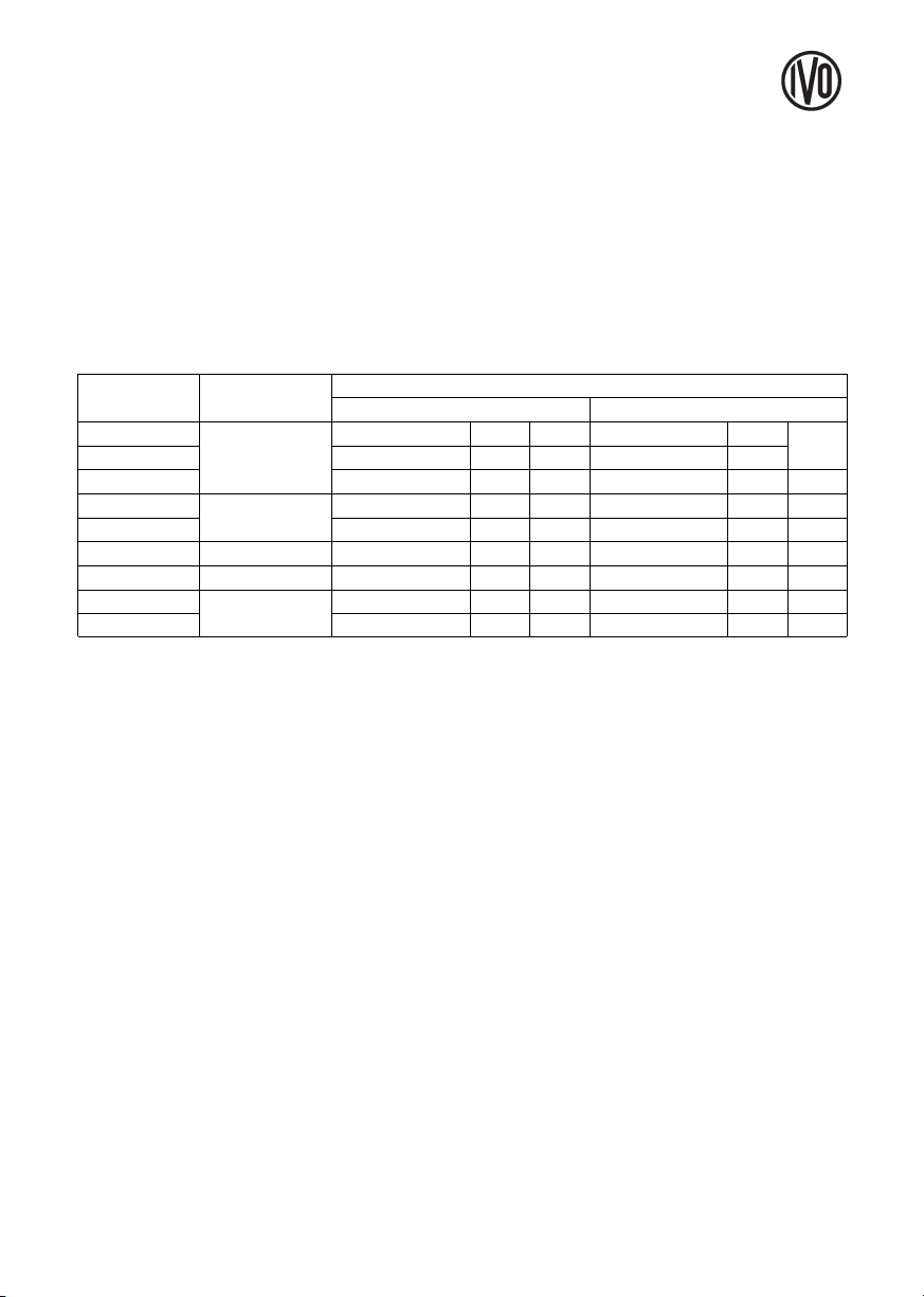
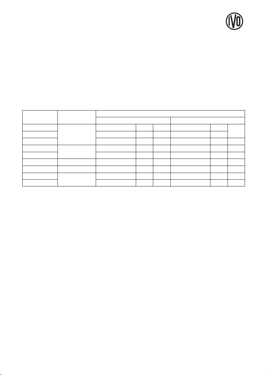
Eingangsspezifikation und Anschlussbelegung AC-Ausführungen
Schraubklemme Nr. 1
INP A
AC/DC
Nr. 2 Nr. 3
INP B
AC/DC
Nr. 4 Nr. 5 Nr. 6 Nr. 7 Nr. 8
ISI30.013AX01
ISI31.013AX01
ISI32.013AX01
zählen
Gemeinsamer
Anschluss für
INP A und INP B
Reset Enable
Verriegelungsein-
gang für Rück-
setztaste NPN.
Beschaltet nach
GND. Taste frei-
geschaltet.
frei
Rücksetz-
eingang NPN
GND =
0 V DC
Hintergrund-
beleuchtung (–)
Hintergrund-
beleuchtung (+)
Schraubklemme 1 und 3:
Funktion siehe Tabelle 3
Optokoppler-Eingang 10 ... 260 V AC/V DC
galvanisch entkoppelt, aktiv bei High-Signal
min. Impulszeit: 16 ms
max. Frequenz: ca. 30 Hz
Low-Pegel: 0 ... 2 V AC/V DC
High-Pegel: 10 ... 260 V AC/V DC
Eingangswiderstand: ca. 160 kOhm
Schraubklemme 2:
Common AC/DC, gemeinsamer Anschluss für
Optokoppler-Eingänge (Schraubklemme 1 und
Schraubklemme 3).
Schraubklemme 4:
Elektrische Verriegelung der Rücksetztaste
Kontakteingang / Open Collector NPN
(nach 0 V DC schaltend)
Low-Pegel: 0 ... 0,7 V DC
High-Pegel: 3 ... 5 V DC
Eingangswiderstand: ca. 2,2 MOhm
Eingang unbeschaltet:
Rücksetztaste verriegelt
Eingang beschaltet nach GND:
Rücksetztaste freigeschaltet
Schraubklemme 5:
Funktion siehe Tabelle 3, aktiv bei negativer Flanke
Kontakteingang/Open Collector NPN
(nach 0 V DC schaltend)
Low-Pegel: 0 ... 0,7 V DC
High-Pegel: 3 ... 5 V DC
min. Impulsdauer: 50 ms
Eingangswiderstand: ca. 2,2 MOhm
Eingang High: - - -
Eingang Low: Zähler wird zurückgesetzt
Rücksetzverhalten dynamisch
Schraubklemme 6:
Gemeinsamer GND-Anschluß für Schraubklemme 4
(Rücksetztaste-Verriegelungseingang) und
Schraubklemme 5 (Rücksetzeingang)
Schraubklemme 7:
(–) externe Spannung bei Option Hintergrund-
beleuchtung
Schraubklemme 8:
(+) externe Spannung bei Option Hintergrund-
beleuchtung (24 V DC
±
20%, 50 mA)
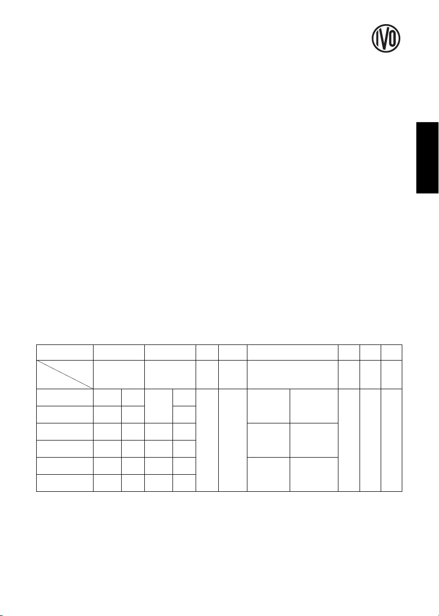
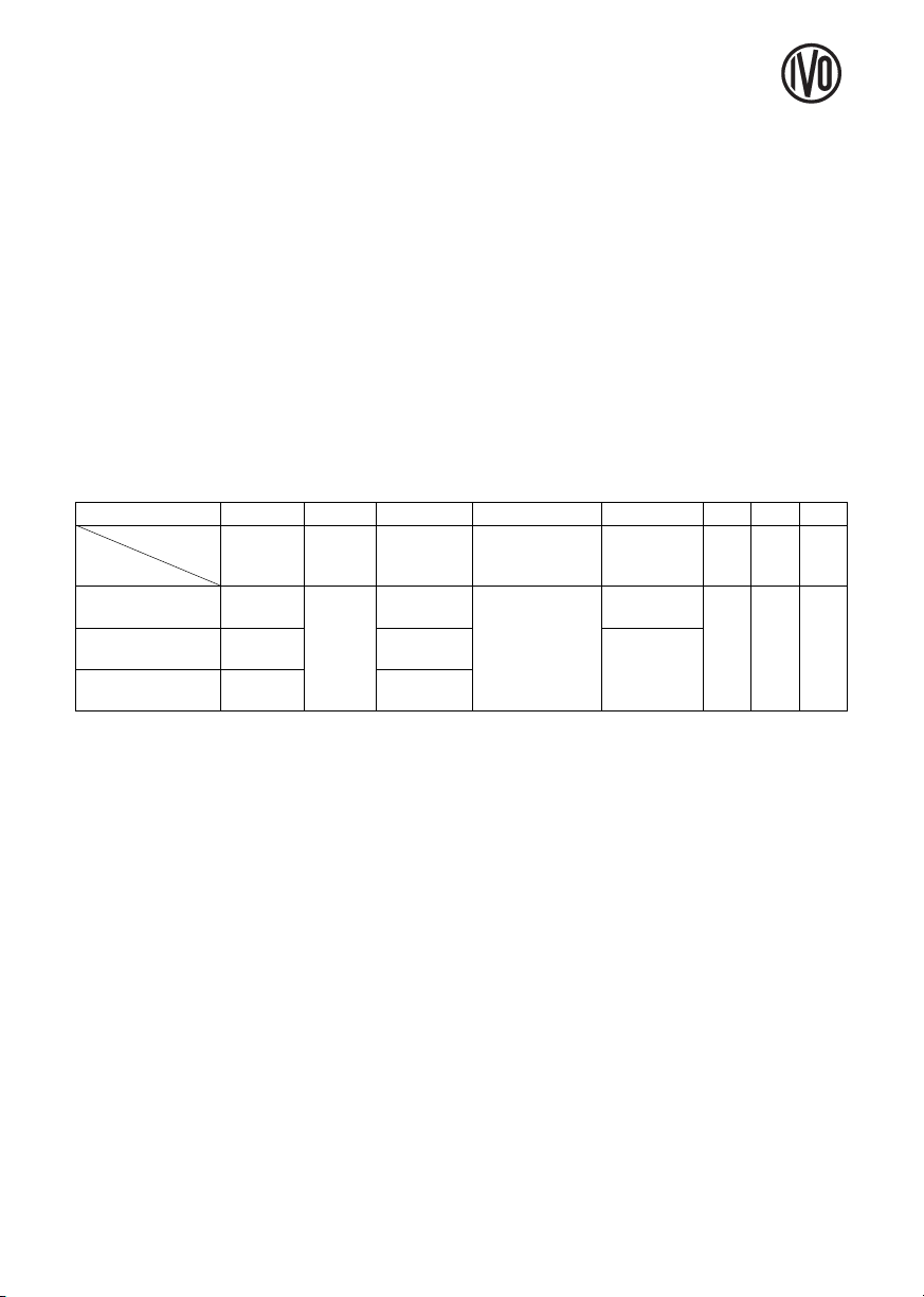
Bezeichnung
Typ
Common
AC/DC
Reset GND BL
–
BL
+
addierensubtrahie-
ren
Zählrichtung
rücksetzen
zählen
Tabelle 3