ivo NE210 User manual

06.05 171.02.154/3
Subject to modification in
technic and design.
Errors and omissions exepted.
Contents Page
1 Safety instructions 2
2 Getting to know the counter 4
3 Counter connection 4
3.1 Connecting the power supply 5
3.2 Assignment signal output „relays contact“ 5
3.3 Assignment electronic output 6
3.4 Assignment signal input 6
3.4.1 Typical connections 8
3.5 Connecting the sensor supply 8
3.6 Establishing basic settings 9
3.6.1 Settings operating modes 9
3.6.2 Setting the counting frequency 9
3.7 Executing the test routine 10
4 Operating mode 10
5 Programming mode 12
5.1 Counting modes (Input modes) 15
5.2 Output responses (Output modes) 19
5.3 Counter overrun response 19
6 Technical data 20
6.1 Dimensions 21
6.2 Default settings 22
6.3 Error messages 22
7 Order designations 22
IVO GmbH & Co. KG
P.O. Box 3360 •D-78022 Villingen-Schwenningen
Phone +49 (0)7720 942-0 •Fax +49 (0)7720 942-900
A Member of the Baumer Group
Operating Instructions
Electronic preselection counter
NE210
COUNTERS CONTROLLERS ENCODERS

2
NE210
General Information
In the following you will find the explanations of the symbols used
in this operating manual.
Explanation of symbols
➜This symbol indicates activities to be carried out.
●This symbol indicates supplementary technical information.
This symbol is located before texts to which particular
attention is to be paid to ensure proper use of the product.
This symbol is located before texts that provide important additional
information.
Italics
Important terms in the left text column are printed in italics
to help you find information more quickly.
1 Safety instructions
1.1 General information
The products has been developed and built in accordance with the
recognized rules of technology. The units have left the
manufacturing plant ready to operate and in safe condition.
To keep the units in this condition, it is necessary that the units be
installed and operated
–properly,
–in a safety and hazard-conscious manner,
–under observance of this operating manual and in particular of
these safety precautions!
Make sure that the personnel has read and understood the operating
manual, and in particular the "Safety Instructions" chapter.
In addition to the operating manual, the generally applicable legal
and other binding regulations for accident prevention and environ-m
ental protection must be observed and ensured.
1.2 Proper use
The application of the units consists of controlling and monitoring
industrial processes in the metal, wood, plastics, paper, glass and
textile industry etc.
The units may only be operated
–in the properly installed state and
–in accordance with the specifications of the technical data!
Operation not covered by the specified descriptions/parameters is
improper and can lead to
–fatal injuries,
–serious damage to health,
–property damage or
–damage to the units
in conjunction with the systems/machines/processes to be
controlled/monitored!
General Information / Safety Instructions

3
NE210
The overvoltages to which the units are subjected at the connection
terminals must be limited to the value of the overvoltage category II
(see Technical data)!
The units may not be operated
–in hazardous areas,
–as medical units,
–in applications expressly named in EN 61010!
If the units are used to control/monitor machines or processes with
which, as the result of a failure/malfunction or incorrect operation of
the units
–a life-threatening danger,
–health risks or
–a danger of property or environmental damage
could result, then appropriate safety precautions must be taken!
Do not open the housing of the units or make any
changes to it!
Tampering with the units can have a negative affect on their
operating safety, resulting in dangers!
Do not make repairs on the units! Return defective units to the
manufacturer!
1.3 Installation/commissioning
In case of changes (including in the operating behavior) that
impair safety, shut-down the units immediately.
Installation may only be carried out in accordance with the
procedure described in Chapter 3 "Counter connecting".
During installation work on the units, the power supply must
always be disconnected. Installation work may only be carried out
by appropriately trained experts.
Max. voltage 250 V terminal - terminal, ground - terminal.
Following proper assembly and installation, the units are ready for
operation. Following commissioning, familiarize yourself with the
use of the units in Chapter 4 "Operating mode".
1.4 Maintenance/repairs
Always disconnect the power supply of all units involved.
Maintenance and repair work may only be carried out by
appropriately trained experts.
If troubleshooting is unsuccessful, do not continue to use the units.
Please contact the manufacturer in this case.
Safety Instructions

4
NE210Getting to know the counter
2 Getting to know the counter
The counter is an electronic, microprocessor-based presetting
counter. It can also be programmed to function as a:
–Time counter with various timescale options
–Time delay relay with four operating modes
3 Counter connection
This section describes the terminal assignments, accompanied by an
example of a typical connection.
Sections 3.1 to 3.5 contain specific instructions and technical data
relating to the individual terminals.
Connection example
Terminal Function
1 Not assigned
2 Power supply
3 Power supply
4
5 1 Signal output - relay contact
6
7 Track A
8 Track B
9 Reset by external signal
10 Electronic output (choice of PNP or NPN logic)
11 Coding input for input logic
12 Sensor supply (0 V)
13 Sensor supply (+24 V)
Display
Selector key for programming/
operating mode
Reset key C
Setting key for decade values
Parameters/LED display
Current main counter
Preset value
Scaling factor
Control panel
Selector key for programming/operating mode
Reset key C
Setting key for decade values
Setting key for decade selection
LEDs symbol display
Setting key for decade
selection
+24V 0V
Sensor
supply
Fuse
SUPPLY
Terminal - Terminal / - Terminal
max. 250 V
A
B
Count
Reset
Electr. output
NPN Br. 11-13
PNP Br. 11-12
Main contact
13 12 11 10 9 8 7
654321

5
NE210
For protection against shock hazards as specified in VDE 0411 part
100, stranded conductors may only be connected using wire end
ferrules with insulating caps. Terminals which are not assigned in
the factory must not be otherwise assigned by the user. We
recommend shielding all encoder connecting leads and earthing
the shield at one end. Earthing at both ends is recommend to avoid
RF interference or if equipotential bonding conductors are installed
over long distances. Encoder connecting leads should not be laid in
the same trunking as the mains power supply cable and output
contact leads.
3.1 Connecting the power supply
AC voltage connection
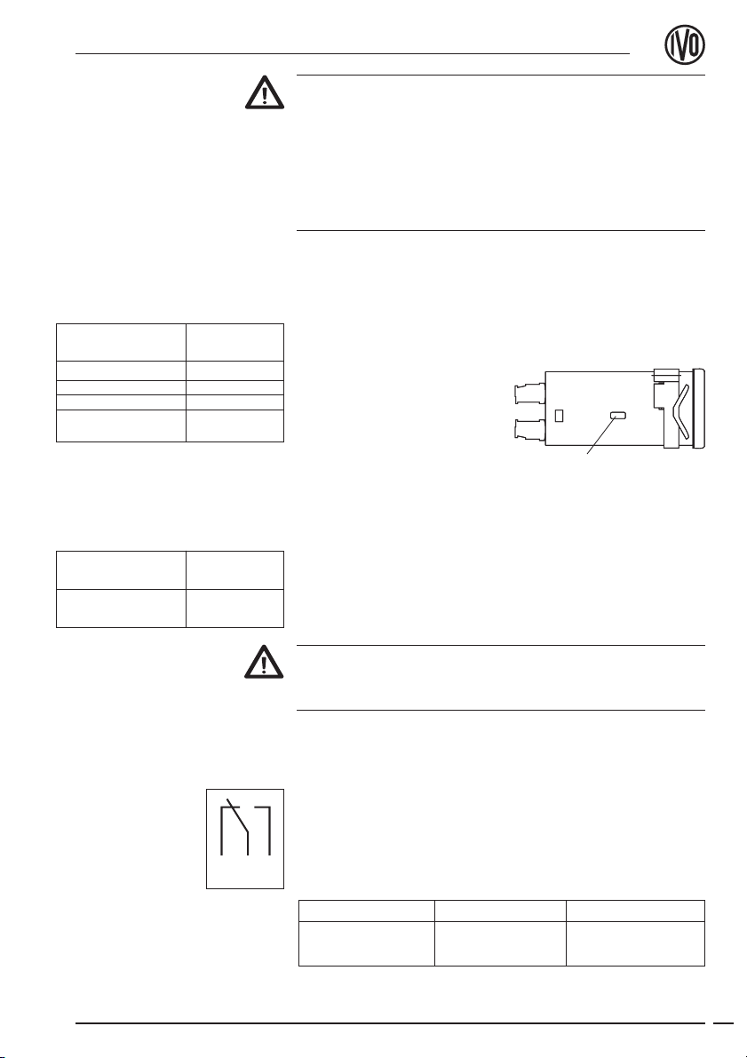
It is possible to switch between two different alternating voltage
ratings (see adjoining table) by means of the voltage selector switch
at the side of the unit. The higher of the two alternating voltage
ratings (48V or 230V) is preset by the factory.
➜Set the required alternating
voltage with the voltage
selector switch.
➜Connect the alternating
voltage supply to terminals 2
and 3 in accordance with the
counter wiring diagram.
DC voltage connection
Connect an interference-free power supply, i.e. do not use it for the
parallel connection of drive systems, contactors, solenoid valves, etc.
➜Connect the DC voltage in accordance with the counter wiring
diagram.
Fire protection: Operate the instrument using the recommended
external fusing indicated in the terminal diagram. VDE 0411
specifies that 8A/150 VA(W) must never be exceeded in the event
of a fault.
3.2 Assignment signal output „relay contact“
Terminals 4, 5 and 6 form a no-potential changeover contact, which
can be assigned as a pulse or continuous contact in accordance with
the adjoining wiring diagram.
Implementation as a pulse or continuous signal is effected via DIP-
switch 2 and in the programming mode, line 12 (see 3.6). The pulse
time is programmed in the programming mode, line 2.
Counter connecting
Voltage selector
6 5 4
Power supply Recommended
AC voltage external fusing
24V ±10% 50/60 Hz M 400 mA
48V ±10% 50/60 Hz M 400 mA
115V ±10%50/60 Hz M 125 mA
230V +6/ -10 %
50/60 Hz M 125 mA
Power supply Recommended
AC voltage external fusing
24 V ±10 %
approx. 5 % RW M 400 mA
Max. switching Max. switching Max. switching
output voltage current
150 VA/30 W 250 V 1A
Table of contents
Other ivo Cash Counter manuals