ivo NE131 User manual

Deutsch English France Italy Spanish
Betriebsanleitung NE131
Einbau
Das Gerät ist als Einbaugerät in Innenräumen konzipiert. Einbaumaße, Einbau-
öffnung sowie das Zubehör ersehen Sie aus den nachfolgenden Zeichnungen.
1 Gerät mit Dichtung von vorne in die Einbauöffnung schieben
2 Spannrahmen von hinten über das Gehäuse schieben und einrasten.
60,8
48
48
44,7
18,5
108
Dichtung
1-6
7
Spannrahmen
55 min.
45 +0.6
55 min.
45 +0.6
60 -0.2
48.7 -0.6
45.45 ±0.25 Senkung
Af4 DIN 74
63 ±0.2
75 -0.2
R1
8.3
3
4.3
Einbauöffnung Adapterplatte Z 118.033
IVO GmbH & Co. KG
Dauchinger Str. 58-62 •D-78056 Villingen-Schwenningen
Phone +49 (0)7720 942-0 •Fax +49 (0)7720 942-900
A Member of the Baumer Group

NE131
2
Sicherheitshinweise
– Dieses Gerät ist nach den geltenden Regeln der Technik gebaut und
geprüft. Das Gerät hat das Werk in sicherheitstechnisch einwandfreiem
Zustand verlassen.
– Benutzen Sie das Gerät nur in technisch einwandfreiem Zustand,
bestimmungsgemäß, sicherheits- und gefahrenbewusst, unter
Beachtung der Betriebsanleitung.
– Das Gerät ist als Einbaugerät in Innenräumen konzipiert. Der Anwen-
dungsbereich des Gerätes liegt in industriellen Prozessen und Steuerun-
gen, wobei die Überspannungen denen das Gerät ausgesetzt ist, auf
den Wert der Überspannungskategorie II begrenzt sein müssen.
– Einbau und Installation dürfen nur von einer Elektrofachkraft durchge-
führt werden. Bei Installationsarbeiten am Gerät ist die Stromversor-
gung unbedingt abzuschalten. Vorsicht: Durch unsachgemäße Reparatur/
Installation können erhebliche Gefahren für den Menschen entstehen.
Vor Inbetriebnahme ist sicherzustellen, dass die angeschlossenen
Betriebs- und Steuerspannung entsprechend den technischen Daten
nicht überschritten werden.
– Wenn durch Ausfall oder Fehlfunktion des Gerätes eine Beschädigung
der Betriebseinrichtung oder die Gefährdung von Mensch und Tier
möglich ist, muss dies durch Sicherheitsvorkehrungen verhindert
werden.
Dieses Symbol steht bei Textstellen, die besonders
zu beachten sind.
Bestellbezeichnung
1 mit einer Vorwahl
2 mit zwei Vorwahlen
2 Spannung 85...265 VAC
3 Spannung 10...30 VAC/VDC
NE131.0 AX01

Deutsch
NE131
3
Anschluss
Das Gerät wird über die beigefügten steckbaren
Schraubklemmen angeschlossen.
Der max. Aderquerschnitt beträgt 1,5 mm2.
Anschlussbelegung
1 Betriebsspannung AC/DC (siehe Typenschild)
2 Betriebsspannung AC/DC (siehe Typenschild)
3 Gemeinsamer Anschluss Count, Reset
4 Count
5 Reset
6 Endkontakt (Schließer)
7 Endkontakt (Wechsler)
8 Endkontakt (Öffner)
9 Keylock
10 Keylock
11 nicht belegen
12 nicht belegen
13 Vorkontakt (Schließer)
14 Vorkontakt (Wechsler)
15 Vorkontakt (Öffner)
Anschlussbilder
Bei Litzenanschluss Aderendhülsen mit Isolierstoff-
kappen verwenden. Betriebsspg. siehe Typenschild.
Endkontakt = P1 bei 1 Vorwahl
Endkontakt = P2 bei 2 Vorwahlen
Belegung 9-15 nur bei
Zählerausführungen
mit zwei Vorwahlen vorhanden
10 9
15 14 13
Vorkontakt
Keylock
~/…
~/… ~/…
Max. 265 V
Klemme - Klemme / - Klemme
Endkontakt
Reset
Count
Netz
315 mA M
85-265 V ~
50-60 Hz
12-260 V
876 5 4321
10-30 V
50-60 Hz
21
Netz
250 mA M
– (+)
+ (–)
Vorkontakt = P1 bei
2 Vorwahlen
Installation
}
}

NE131
4
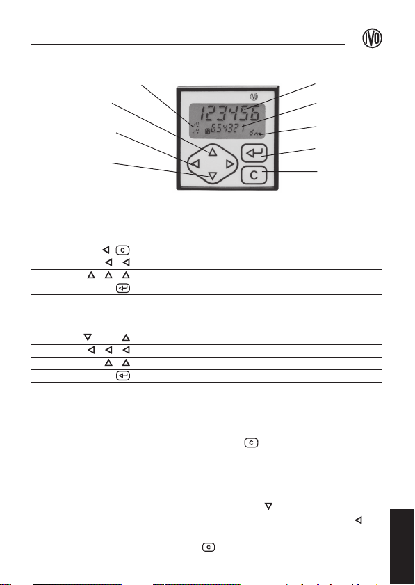
Anzeige 7-Segment LCD-Display zweizeilig
Ziffernhöhe Erste Zeile 7 mm, zweite Zeile 4 mm
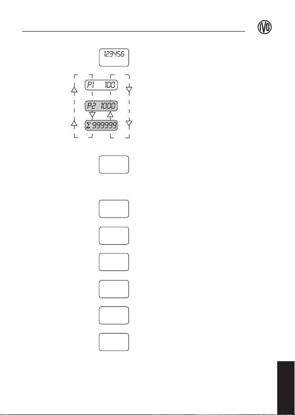
Zählbereich Von 0 bis 999999 (6-stellig)
Tastatur 6 Kurzhubtaster, Polyesterfrontfolie
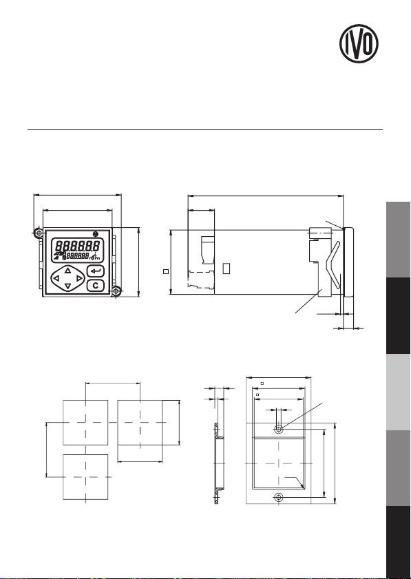
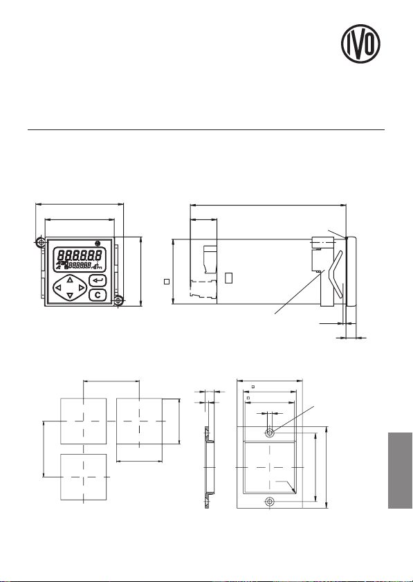
Frontmaß 48 x 48 mm
Einbautiefe Gesamt 108 mm
Einbauöffnung 45+0,5 x 45+0,5 mm, Fronttafel max.12 mm
Befestigung Mittels Spannrahmen
Anschlusstechnik Steckbare Schraubklemmen
Aderquerschnitt Max. 1,5 mm2
Gehäusematerial Polycarbonat schwarz, UL 94V-0
Gewicht Ca. 140 g
Betriebsspannung 85...265 VAC oder 10...30 VAC/VDC
Leistungsaufnahme 2 W
Zähl- und Rückstellspg. 12...260 VAC/VDC
Zählfrequenz 25 Hz, (1 kHz bei DC-Ansteuerung)
Mindestimpulsdauer 20 ms (0,5 ms)
Rückstellimpulsdauer ≥20 ms
Datenspeicherung > 10 Jahre durch EEPROM
Relaisausgang 1 oder 2 potentialfreie Wechsler
Max. Schaltspannung 260 VAC
Max. Schaltstrom 1 A
Max. Schaltleistung 150 VA / 30 W
Ansprechzeit ca. 5 ms
Umgebungstemp. 0...+50 °C
Lagerungstemp. -20...+70 °C
Luftfeuchtigkeit Max. relative Feuchte 80 %, nicht betauend
Schutzart Frontseite IP 65 nach DIN 40050
Allg. Anforderungen EN 61010 Teil 1
- Schutzklasse II
- Überspannungskategorie II
- Verschmutzungsgrad 2
Störfestigkeit EN 61000-6-2
Störaussendung EN 50081-2
Technische Daten

Deutsch
NE131
5
Display- und Tastenfunktionen
Vorwahleingabe
Beispiel: P1 auf 30 einstellen
Taste Funktion
Bestehenden Vorwahlwert löschen
Eingabe starten und 2. Ziffer anwählen (Ziffer blinkt)
Wert 3 eingeben
Vorwahleingabe P1 quittieren
Beispiel: P2 auf 200 einstellen
Taste Funktion
oder Anwahl von P2 (2. Zeile zeigt P2 an)
Eingabe starten und 3. Ziffer anwählen (Ziffer blinkt)
Wert 2 eingeben
Vorwahleingabe P2 quittieren
Hinweis
Der Zugang kann durch einen Code geschützt
werden. Siehe Menüzeile Nr. 41.
Zählerstand rückstellen
Drücken Sie die Taste um den Zählerstand
zurückzustellen.
Hinweis
In Menüzeile 25 kann die Rückstellung gesperrt werden.
Totalisator rückstellen
Wählen Sie über die Taste den Totalisator an, das
Display zeigt Σ an. Jetzt drücken Sie die Taste der
Anzeigewert des Totalisators blinkt. Nun drücken
Sie die Taste um den Totalisator zurückzustellen.
Vorwahlanzeige P1 (P2)
Display-Anwahl / Wert
um 1 erhöhen
Eingabe starten Ziffer
nach links / rechts
Display-Anwahl / Wert
um 1 verringern
Zählerstand
Vorwahlwert
(Totalisator)
Maßeinheit
Eingabe-
Quittierung
Rückstellung
Bedienung

NE131
6
Einstellung der Funktionen
Im Konfigurationsmenüersehen Sie die
Funktions-
einstellungen die beim ersten Einschalten des
Zählers wirksam sind (Werkseinstellung). Hier
nehmen Sie auch die optimale Einstellung für Ihre
Aufgabenstellung vor. Die nachfolgende Tabelle
zeigt Ihnen den Zugang zum Konfigurationsmenü
sowie die Funktionsauswahl.
Hinweis
Der Zugang kann durch einen Code geschützt
werden. Siehe hierzu Menüzeile Nr. 42.
Tastenfunktionen
Taste Funktion
Konfigurationsmenüaufrufen bzw. beenden.
gleichzeitig drücken (Im Display erscheint Code)
Solange kein Code hinterlegt ist nur quittieren
Zugangscode z.B. 11 eingeben und quittieren.
oder Menüzeilen-Nr. anwählen
oder Eingabe starten u. Ziffer anwählen (Ziffer blinkt)
oder Funktionswert bzw. Funktions-Nr. eingeben
Eingabe quittieren
und Reset auf Werkseinstellung: Tasten gedrückt
gleichzeitig halten u. Netzspg. einschalten. Anzeige CLrPro
Konfigurations-Display
Das Display zeigt hier auf einen Blick die Menü-
zeilen-Nr. und den Funktionswert bzw. die
Funktions-Nr. an.
Display-Beispiele
Funktionswert:
Skalierungsfaktor 0.0001...9999.99
Menüzeilen Nr.
Funktions-Nr.:
Betriebsart 0 = addierend
1 = subtrahierend
Konfigurieren
1.0000
21
0
22

Deutsch
NE131
7
Bedienmenü
Zählerstand
Die erste Display- Zeile zeigt den
aktuellen Zählerstand an.
Vorwahl P1
Die zweite Display-Zeile zeigt den...
Vorwahlwert P1
Vorwahl P2*
Vorwahlwert P2*
Totalisator (bei Multifunktion 1 und 3)
Totalisator Σ
Konfigurationsmenü
Multifunktion 0 Impulszählung
1 Impulszählung mit Totalisator Σ
2 Zeitzählung
3 Zeitzählung mit Zeit-Totalisator Σ
Skalierungs- 0.0001
faktor 9999.99 (max.)
Betriebsart 0 addierend
0,1,2,3...P1...P2*
1 subtrahierend
P2*...P1...3,2,1,0
Vorwahlmode* 0 Stufenvorwahl
nach P1 folgt P2
1 Schleppvorwahl
P1 = Differ. vor P2
automatische 0 ja
beim Endkontakt
Rückstellung 1 nein
C-Tasten 0 freigegeben
Zählerstand
Rückstellung 1 gesperrt
Vorwahl- 0 mit Rückstellung
Quittierung 1 ohne Rückstellung
Menüs
1.0000
21
0
22
0
23
0
24
0
25
0
26
0
20

8
NE131
Signaldauer 0.01 [s]
zur Eingabe
Endkontakt 99.99 [s]
kurz
Latch [Dauersignal]
dann drücken
Signaldauer 0.01 [s]
zur Eingabe
Vorkontakt * 99.99 [s]
kurz
Latch [Dauersignal]
dann drücken
Signallogik 0 Schließer
bei erreichter 1 Öffner
Vorwahl 2 * P1 Öffner, P2 Schließer
3 * P1 Schließer, P2 Öffner
Dezimalpunkt/ 0 0 / 999.99 s
Zeitbereich 1 0.0 / 999.59.9 min
2 0.00 / 9999.59 min
3 0.000 / 9999.59 h
Zählfrequenz 0 25 Hz
1 1 kHz
nur bei DC-Ansteuerung
Maßeinheit im 0 ohne Maßeinheit 5 L
Display 1 m 6 h
2 dm 7 min
3 cm 8 s
4 mm
Grundanzeige 0 nicht aktiv
der 2. Zeile 1 P1 Vorwahlwert
2 P2 Vorwahlwert * Rücksprung
3 Totalisator nach ca. 15 s
Bedien-Code 0 nicht aktiv
1 ...9999
Menü-Code 0 nicht aktiv
1 ...9999
* Menüzeile bzw. Funktion bei Zählern mit zwei Vorwahlen vorhanden.
0.25
27
0.25
28
0
29
0
30
0
31
0
32
0
33 (2)
0
41
0
42
}

English
9
Operating Instructions NE131
Mounting
The instrument is designed as built-in counter for in-door use. Please refer
to the following drawings for the cutout measures, the cutout size, as well
as the mounting accessories.
1 Shove instrument with gasket from the front inside the cutout.
2 Shove clamping frame from the back over enclosure and fasten.
60.8
48
48
44.7
18.5
108
Packing
1-6
7
clamping frame
55 min.
45 +0.6
55 min.
45 +0.6
60 -0.2
48.7 -0.6
45.45 ±0.25
Counter-
sinking
Af4 DIN 74
63 ±0.2
75 -0.2
R1
8.3
3
4.3
Cutout size Adapter plate Z 118.033

10
NE131
Safety Indications
–This instrument has been constructed and tested according to the state
of the art, and has left the factory in an absolutely perfect state with
regard to safety concerns.
–Use the instrument only in a perfectly safe technical state, for the
intended purpose, conscious of relevant safety and danger, and by
observing its operating instructions.
–The instrument has been designed as built-in device for indoor use in
industrial processes and controls where the overvoltage exerted on the
instrument must be limited to the voltage values of category II.
–Mounting and installation may only be effected by an expert on the field
of electricity. Power supply has to be switched off during any installation
procedures. Attention: Any improper repairs/installments may cause
considerable danger to persons. Prior to initial operation, please make
sure that the operating and control voltages do not exceed the ones as
indicated under technical data.
–If the operating facilities could be damaged or living beings could be
injured as a result of the break-down or failure of the device, this needs
to be avoided by taking relevant safety precautions.
This symbol stands next to text passages that need
special attention.
Order Designation
1 With one preset
2 With two presets
2 Voltage 85 to 265 VAC
3 Voltage 10 to 30 VAC/VDC
NE131.0 AX01

English
11
NE131
Connection
The instrument is connected via the enclosed plug-
in screw terminals. Maximum size of core cross-
section is 1,5 mm2.
Assigned contacts
1 Power supply AC/DC (please refer to nameplate)
2 Power supply AC/DC (please refer to nameplate)
3 Common connection Count, Reset
4 Counting
5 Reset
6 Main cont. (nor. open)
7 Main cont. (changeover)
8 Main cont. (nor. closed)
9 Keylock
10 Keylock
11 Not assigned
12 Not assigned
13 Leader cont. (nor. open)
14 Leader cont. (changeover)
15 Leader cont. (nor. closed)
Pin assignment
For litz connection, use connector sleeves with
insulating enclosures. For power supply, please
refer to nameplate.
Main contact = P1
with 1 preset
Main contact = P2
with 2 presets
Assignment 9-15 only
available for counter
models with 2 presets
Leader contact = P1
with 2 presets
Installation
pre contact
Keylock
15 14 13 10 9
~/…
~/…~/…
Max. 265 V
Reset
Count
315 mA M
85-265 V ~
50-60 Hz
12-260 V
876 5 4321
10-30 V
50-60 Hz
21
250 mA M
–(+)
+ (–)
terminal to terminal / to terminal
Supply
Final contact
Supply
}
}

12
NE131
Display 7-segment LCD-display with two lines
Digit height First line 7 mm, second line 4 mm
Counting range From 0 to 999999 (6-digit)
Keyboard 6 short-stroke keys, Polyester front foil
Front dimension 48 x 48 mm
Mounting depth 108 mm in total
Cutout size 45 +0.5 x 45 +0.5 mm, Front pan. max.12 mm
Fixing By means of clamping frame
Type of connection Plug-in screw terminals
Core cross-section Max. 1.5 mm2
Enclosure material Polycarbonate black, UL 94V-0
Weight Ca. 140 g
Power supply 85...265 VAC or 10...30 VAC/VDC
Power consumption 2 Watt
Counting and
reset voltage 12...260 VAC/VDC
Counting rate 25 Hz, (1 kHz with DC - triggering)
Least pulse duration 20 ms (0.5 ms)
Reset pulse duration ≥20 ms
Data storing > 10 years by means of EEPROM
Relay output 1 or 2 floating changeover contact
max. switching voltage 260 VAC
max. switching power 1 A
max. switching capa. 150 VA / 30 Watt
Response time ca. 5 ms
Ambient temperature 0...+50 °C
Storage temperature -20...+70 °C
Relative humidity Max. 80 %, non-condensing
Protection Front IP 65 according to DIN 40050
General rating EN 61010 Teil 1
- Protection class II
- Overvoltage protection category II
- Contamination factor 2
Interference immunity EN 61000-6-2
Emitted interference EN 50081-2
Technical Data

English
13
NE131
Display and Key functions
Enter presets
Example: Set P1 to 30
Key Function
Clear present preset value
Start input and select 2 nd digit (digit starts to blink)
Enter value 3
Confirm preset of P1
Example: Set P2 to 200
Key Function
or Selection of P2 (2nd line displays P2)
Start entry and select 3 rd digit (digit starts to blink)
Enter value 2
Confirm preset of P2
Hint
Access can be secured by code. Menu line no. 41.
Clear count
Press the key to clear count.
Hint
Clearing can be locked in menu line 25.
Clear totalizer
Select totalizer via key and the display will
indicate Σ. Now press the key and the value
displ. of total. starts blinking. Now press the key
to clear the totalizer.
Preset P1 (P2)
Display selection /
Increase value by 1
Start input
Digit to the left /right
Display selection /
Decrease value by 1
Count
Preset (Totalizer)
Measuring unit
Input
confirmation
Reset
Operation

14
NE131
Setting of Functions
In the configuration menu you will see the function
settings that are effective when turning the counter
on for the first time (factory setting). Here you may
also effect the best setting for your task. The follo-
wing table indicates how to access the configuration
menu as well as how to select functions.
Hint
Access may be protected by a code.
Please refer to menu line no. 42.
Key Functions
Key Function
Call or exit configuration menu.
press simultaneous (Code is indicated on display.)
If no code is entered, quit only
Enter and confirm access code, e.g. 11.
or Select menu line number
or Start entry and select digit (digit starts to blink).
or Enter function value and/or function number.
Confirm entry.
and Reset to default settings: Keep button pressed
simultaneous and connect unit to the mains. Display: CLrPro
Configurations Display
Here the display indicates the menu line number
as well as the function value and/or the function
number, all at one glance.
Display examples
Scaling factor Function value:
0.0001 ... 9999.99
Menu line no.
Function no:
Mode 0 = adding
1 = subtracting
Configuration
1.0000
21
0
22

English
15
NE131
Operation menu
Zählerstand
The first display line indicates the
current count
Preset P1
The 2
nd
display line indicates the...
preset value P1
Preset P2*
preset value P2*
Totalizer (for multifuction 1 and 3)
Totalizer Σ
Configuration menu
Multifunction 0 Impulse meter
1 Impulse meter with totalizer Σ
2 Time measur.
3 Time measur.t. with time totalizer Σ
Scaling factor 0.0001
9999.99 (max.)
Mode 0 adding
0,1,2,3...P1...P2*
1 subtracting
P2*...P1...3,2,1,0
Preset mode* 0 Progr. presel.
P1 followed by P2
1 Trailing presel.
P1=Differ. prior to P2
automatic 0 yes
No main contact
reset 1 no
C-key 0 released
Count
clearing 1 locked
Preset 0 with reset
conformation 1 without reset
Menus
1.0000
21
0
22
0
23
0
24
0
25
0
26
0
20

16
NE131
Sign. duration 0.01 [s]
to enter
Main contact 99.99 [s]
briefly press
Latch [permanent signal]
then press
Sign. duration 0.01 [s]
to enter
Leader cont * 99.99 [s]
briefly press
Latch [permanent signal]
then press
Signal logic 0 Normally open
with preset is 1 Normally closed
reached 2 * P1 norm. closed, P2 normally open
3 * P1 norm. open, P2 normally closed
Decimal point/ 0 0 / 999.99 s
Time range 1 0.0 / 999.59.9 min
2 0.00 / 9999.59 min
3 0.000 / 9999.59 h
Counting range 0 25 Hz
1 1 kHz
only with DC-triggering
Measuring unit 0 w/o measuring unit 5 L
displayed 1 m 6 h
2 dm 7 min
3 cm 8 s
4 mm
Basic display 0 not active
2nd line 1 P1 preset
2 P2 preset * Reset after
3 Totalizer about 15 s
Operating code 0 not active
1 ...9999
Menu code 0 not active
1 ...9999
* Menu line and/or function available for counters with the presets.
0.25
27
0.25
28
0
29
0
30
0
31
0
32
0
33 (2)
0
41
0
42
}

Guide utilisateur NE131
Montage
L‘appareil a été conçu pour être encastré. Les dimensions, plan de découpe
ainsi que les accessoires de montage sont représentés ci-dessous.
Découpe Cadre Z 118.033
1. Introduire l‘appareil avec son joint dans la découpe.
2. Monter l‘étrier par l‘arrière.
60,8
48
48
44,7
18,5
108
1-6
7
etrier
étancheité
55 min.
45 +0.6
55 min.
45 +0.6
60 -0.2
48.7 -0.6
45.45 ±0.25 Af4 DIN 74
63 ±0.2
75 -0.2
R1
8.3
3
4.3
France

18
NE131
Sécurité installation
– L‘appareil a été construit et testé conformément aux normes en vigueur.
– L‘appareil a été conçu pour fonctionner en toute sécurité si les
instructions fournies dans les documents d‘accompagnement sont
respectées.
– Le domaine d‘application est l‘industrie et en particulier l‘automatisme.
Les surtensions aux quelles l‘appareil peut être soumis ne doivent pas
dépasser la catégorie II. Le montage de l‘appareil est de type encastré
dans le panneau frontal.
– L‘installation de l‘appareil ne doit être effectuée que par un personnel
qualifié. A l´installation de l´appareil la tension d´alimentation doit être
coupée. Attention: Le non respect des régles de sécurité peut présenter
des dangers pour l´homme.
– Si la défaillance du produit peut occasionner des dégats matériels ou
corporels il est nécessaire de prévoir des systèmes de sécurité.
Ce symbole attire l‘attention sur les points à
respecter particulièrement lors de la mise en
service de l‘appareil.
Référence de commande
1 Compteur à 1 présélection
2 Compteur à 2 présélections
2 Alimentation 85 à 265 VAC
3 Alimentation 10 à 30 VAC/VDC
NE131.0 AX01

19
NE131
Branchement
Par connecteurs débrochables avec bornes à visser,
section 1,5 mm2max.
Raccordement
1 Alimentation AC/DC
2 Alimentation AC/DC
3 Commun comptage, Repositionnement
4 Comptage
5 Repositionnement (RAZ)
6 Contact final (fermeture)
7 Contact final (inverseur)
8 Contact final (ouverture)
9 Keylock
10 Keylock
11 Réservé
12 Réservé
13 Pré-contact (fermeture)
14 Pré-contact (inverseur)
15 Pré-contact (ouverture)
Schéma de branchement
Pour le raccordement prévoir des embouts de
cablage. Vérifier la tension d‘alimentation de
l‘appareil sur l‘étiquette type.
Contact final pour compteur à
1 ou 2 présélections
Le connecteur 9-15 n´est
disponible que sur la version 2
présélections.
10 9
15 14 13
Pré-contact
Keylock
~/…
~/… ~/…
Max. 265 V
Borne à visser - Borne à visser - Borne à visser
Contact final
Repos.
Compt.
Alim.
315 mA M
85-265 V ~
50-60 Hz
12-260 V
876 5 4321
10-30 V
50-60 Hz
21
Alim.
250 mA M
– (+)
+ (–)
Pré-contact pour compteur à
2 présélections
Installation
France
}
}

20
NE131
Affichage 7-Segments LCD (2 lignes)
Hauteur 7 mm affichage du haut, 4 mm affichage du bas
Nombre de décades 6 (valeur de 0 à 999999)
Clavier Touches mécaniques à face polyester
Dimensions frontales 48 x 48 mm
Encastrement Profondeur 108 mm
Découpe 45 +0,5 x 45 +0,5 mm, épaisseur max.12 mm
Fixation Par étrier
Raccordement Connecteurs à visser débrochables
Section des fils Max. 1,5 mm2
Matière boitier Polycarbonat sw, UL 94V-0
Poids 140 g
Alimentation 85 à 265 VAC ou 10 à 30 VAC/VDC
Consommation 2 W
Comptage et
repositionnement 12 à 260 VAC/VDC
Fréquence de comptage
25Hz (1kHz en VDC)
Durée d‘impulsion ≥20 ms (0,5 ms)
Durée repositionnement ≥20 ms
Mémoire > 10 ans par EEPROM
Sorties relais Contact inverseur
Pouvoir de coupure 260 VAC
Courant 1A max.
Charge 150 VA / 30 W
Temps de réponse 5 ms
Température
fonctionnement 0 ... +50 °C
Température stockage -20 ... +70 °C
Humidité relative Max. 80 %, sans condensation
Protection IP 65 en façade DIN 40050
Conformité générale EN 61010
- Conformité sécurité II
- Surtension catégorie II
- Classe de protection 2
Immunité EN 61000-6-2
Emission EN 50081-2
Caractéristiques techniques
Table of contents
Languages:
Other ivo Cash Counter manuals
Popular Cash Counter manuals by other brands

HYOSUNG
HYOSUNG MONiMAX5100T Operator's manual

Keysight Technologies
Keysight Technologies 53210A Service guide

UNISource Corporation
UNISource Corporation FC-8300 Operation manual

HIOS
HIOS SC1 Series instruction manual

Met One Instruments
Met One Instruments AEROCET 531S manual

Hengstler
Hengstler tico 732 user manual