Ivy Biomedical Systems 3150-B User manual

Part No. 2718-55-16
OPERATION MANUAL
© 2014 IVY Biomedical Systems Inc. All Rights Reserved. Part No. 2718-24-16
Cardiac Trigger Monitor
Model 3150-B
Designed exclusively to operate with
GE Healthcare CT Scanners
GE Part Number: 5304770

User Responsibility
This product will perform in conformity with the description thereof contained in this Operation Manual and
accompanying labels and/or inserts, when assembled, operated, maintained and repaired in accordance with the
instructions provided. This product must be checked periodically. A defective Product should not be used. Parts that
are broken, missing, plainly worn, distorted or contaminated should be replaced immediately. Should such repair or
replacement become necessary, IVY Biomedical Systems, Inc. recommends that a telephone call or written request
for service advice be made to IVY Biomedical Systems, Inc. Service Department. This product or any of its parts
should not be repaired other than in accordance with instructions provided by IVY Biomedical Systems, Inc. trained
personnel. The product must not be altered without the prior written approval of IVY Biomedical Systems, Inc.
Quality Assurance Department. The user of this Product shall have the sole responsibility for any malfunction,
which results from improper use, faulty maintenance, improper repair, damage or alteration by anyone other than
IVY Biomedical Systems, Inc.
CAUTION: US Federal law restricts this device to sale by or on the order of a licensed medical practitioner.
Ivy Biomedical Systems, Inc. has declared that this product conforms with the Eurpean Council Directive
93/42/EEC Medical Device Directive when its used in accordance with the instructions provided in the Operation
and Maintenace Manual.
Ivy Biomedical Systems, Inc.
11 Business Park Drive
Branford, Connecticut 06405 USA
(203) 481-4183 (800) 247-4614 Fax (203) 481-8734
OM3150-B
3 March 2014
2718-24-16 Rev.02

This page is intentionally left blank.

Table of Contents
Model 3150-B Operation Manual i
Table of Contents
WARRANTY ...................................................................................................................................................... iii
INTRODUCTION ................................................................................................................................................1
SAFETY ................................................................................................................................................................2
Electrical................................................................................................................................................................2
Explosion ...............................................................................................................................................................2
Patient Connections..............................................................................................................................................3
MRI........................................................................................................................................................................3
Pacemakers ...........................................................................................................................................................3
Electrosurgery Protection....................................................................................................................................3
Defibrillation Protection ......................................................................................................................................3
EMC.......................................................................................................................................................................3
Electromagnetic Compatibility IEC 60601-1-2:2001 ..............................................................................3
Description of Warning Labels ...........................................................................................................................7
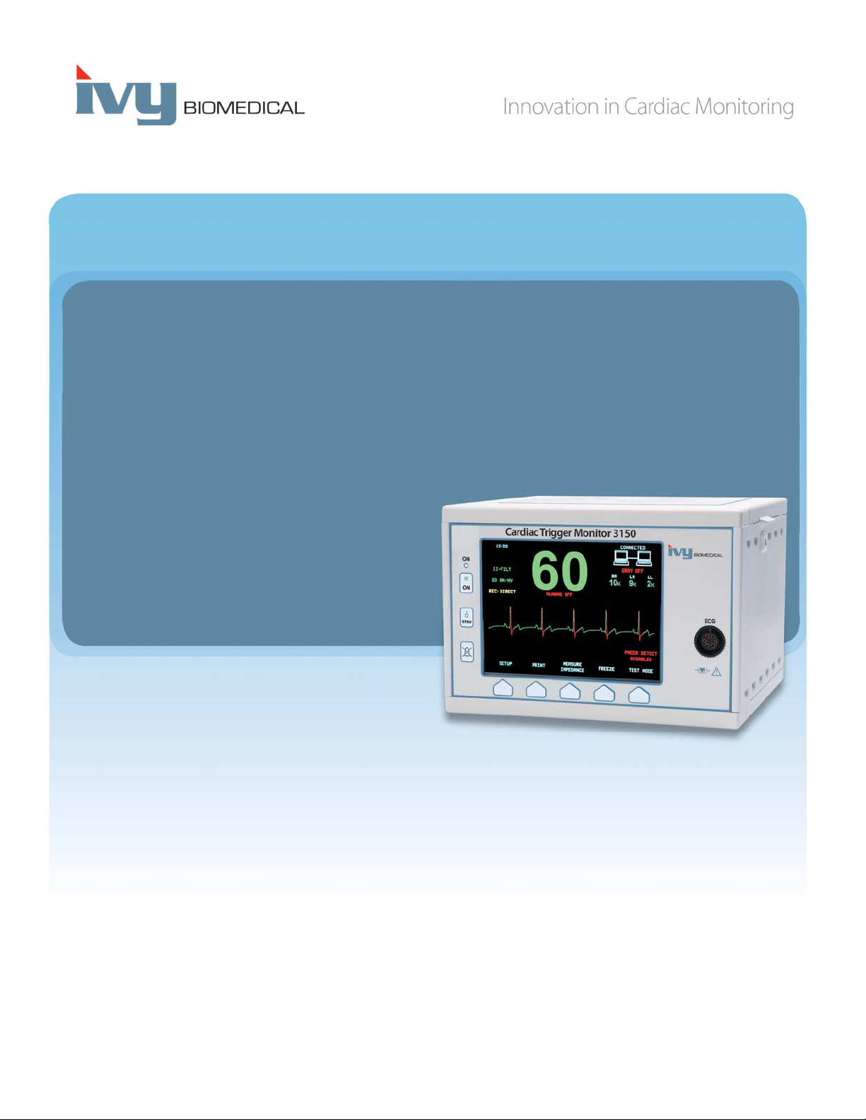
MONITOR DESCRIPTION ...............................................................................................................................8
Classification.........................................................................................................................................................9
Control and Indicators.......................................................................................................................................10
Basic Keys..............................................................................................................................................10
Programmable Keys ...............................................................................................................................11
Menu Structure.......................................................................................................................................12
Display ...................................................................................................................................................13
Alarm Messages .....................................................................................................................................14
Rear Panel ..............................................................................................................................................14
Fuse Ratings ...........................................................................................................................................15
MONITOR SETUP ............................................................................................................................................16
Set up the instrument for operation..................................................................................................................16
Change Mains Voltage .......................................................................................................................................16
Set the Language ................................................................................................................................................16
Set Time, Date, and Audio .................................................................................................................................16
Trace Speed.........................................................................................................................................................17
Default Settings...................................................................................................................................................17
SYNCHRONIZED OUTPUT (TRIGGER) .....................................................................................................18
The Synch Pulse..................................................................................................................................................18
Trigger-Mark Display ........................................................................................................................................18
Polarity Lock (P-Lock).......................................................................................................................................18
ECG MONITORING.........................................................................................................................................19
Safety Considerations.........................................................................................................................................19
Patient Connections............................................................................................................................................20
ECG Electrodes ..................................................................................................................................................21
Impedance Measurement ..................................................................................................................................21
ECG Waveform Amplitude (Size).....................................................................................................................22
Lead Selection .....................................................................................................................................................23
Low Signal Message ...........................................................................................................................................24
ECG Notch Filter................................................................................................................................................24
Alarm Limits.......................................................................................................................................................25
Pacemaker...........................................................................................................................................................25

Table of Contents
ii Model 3150-B Operation Manual
SYSTEM INTERLOCK OPERATION ...........................................................................................................26
System Interlock Messages ................................................................................................................................26
PATIENT IDENTIFICATION NUMBER.......................................................................................................27
Patient Identification and other controls using ETHERNET MODE ...........................................................27
ECG DATA STORAGE AND TRANSFER ....................................................................................................28
ECG and Impedance Data Transfer using the USB Port ..............................................................................28
USB Port..............................................................................................................................................................28
RECORDER OPERATION .............................................................................................................................29
Changing Paper ..................................................................................................................................................29
Recorder Modes..................................................................................................................................................30
Recorder Speed...................................................................................................................................................31
Example Printout................................................................................................................................................31
ALARM MESSAGES ........................................................................................................................................32
Low Signal message...............................................................................................................................32
Pacer Detect message .............................................................................................................................32
Check Electrode message.......................................................................................................................32
MONITOR TESTING .......................................................................................................................................33
ECG Simulator ...................................................................................................................................................33
TROUBLESHOOTING.....................................................................................................................................34
MAINTENANCE AND CLEANING ...............................................................................................................35
Monitor................................................................................................................................................................35
Patient Cables .....................................................................................................................................................35
Preventive Maintenance.....................................................................................................................................35
ACCESSORIES..................................................................................................................................................36
ECG .....................................................................................................................................................................36
Disposal................................................................................................................................................................36
SPECIFICATIONS ............................................................................................................................................37

WARRANTY
Model 3150-B Operation Manual iii
WARRANTY
All products manufactured by Ivy Biomedical Systems, Inc. under normal use, are warranted to be free from defects
in material and workmanship and to operate within published specifications, for a period of 13 months from date of
original shipment.
All accessories such as patient cables and lead wires, supplied by Ivy Biomedical Systems, Inc. under normal use,
are warranted to be free from defects in material and workmanship and to operate within published specifications,
for a period of 90 days from date of original shipment.
If an examination by Ivy Biomedical Systems, Inc. discloses such product(s) or component part(s) to have been
defective, then Ivy’s obligation is limited at Ivy’s option, to repair or replacement.
When a product or products need to be returned to the manufacturer for repair or examination, contact customer
service personnel at Ivy Biomedical Systems, to obtain a Return Material Authorization number (RMA #) and the
correct packing instructions:
Customer Service
Telephone: (203) 481-4183 or (800) 247-4614.
Fax: (203) 481-8734.
E-mail: ivybio@ivybiomedical.com
All products being returned for warranty repair shall be shipped prepaid to:
Ivy Biomedical Systems, Inc.
11 Business Park Drive.
Branford, CT. 06405. USA.
Ivy will prepay the shipment of the repaired or replacement product to customer at Ivy’s expense.

WARRANTY
iv Model 3150-B Operation Manual
This page is intentionally left blank.

INTRODUCTION
Model 3150-B Operation Manual 1
INTRODUCTION
This manual is to provide information on the correct use of the Model 3150-B Cardiac Trigger monitor. It is up to
the user to ensure that any applicable regulations regarding the installation and operation of the monitor are
observed.
The Model 3150-B is a Medical Electrical Equipment intended to monitor patients under medical supervision. The
Model 3150-B monitor must be operated by trained and qualified medical personnel only.
Using This Manual
We recommend that you read this manual before operating the equipment. This manual is written to include all
options. If your monitor does not include all options, menu selections and display data for those options will not
appear on your monitor.
Use the Monitor Description section for general descriptions of controls and displays. For details on the use of each
option, refer to the section of the manual dealing with the appropriate option.
Boldface type is used in text to refer to the labeling on user controls. Special brackets [ ] surround menu
selections used with the programmable keys.
Manufacturer’s Responsibility
The manufacturer of this equipment is responsible for the effects on safety, reliability, and performance of the
equipment only if:
Assembly operations, extensions, re-adjustments, or repairs are carried out by persons authorized by the
manufacturer
The electrical installation complies with all applicable regulations
The equipment is used in accordance with the instructions in this manual
Incorrect operation or failure of the user to maintain the monitor in accordance with proper maintenance procedures
relieves the manufacturer or his agent from all responsibility for consequent non-compliance, damage, or injury.
Ivy Biomedical Systems, Inc.
11 Business Park Drive
Branford, Connecticut 06405
(203) 481-4183 or (800) 247-4614
fax (203) 481-8734
e-mail: techline@ivybiomedical.com
This manual explains how to set up and use the Model 3150-B. Important safety information is located throughout
the manual where appropriate. READ THE ENTIRE SAFETY INFORMATION SECTION BEFORE YOU
OPERATE THE MONITOR.

SAFETY
2 Model 3150-B Operation Manual
SAFETY
Electrical
This product is intended to be operated from a mains power source of nominally 100 to 230V~, 47 to 63 Hz and
Maximum AC Power consumption: 45VA.
WARNING: To prevent electrical hazards to all personnel, this monitor must be properly grounded. Connect the
monitor only to a three-wire, grounded, hospital grade receptacle. The three-conductor plug must be inserted into a
properly wired three-wire receptacle; if a three-wire receptacle is not available, a qualified electrician must install
one in accordance with the governing electric code.
WARNING: Do not under any circumstances remove grounding conductor from the power plug.
WARNING: The power cable supplied with this equipment provides for this protection. Do not attempt to defeat
this protection by modifying the cable or by using ungrounded adapters or extension cables. The power cord and
plug must be intact and undamaged. To disconnect the equipment from the mains power; unplug the power cord.
WARNING: Do not connect to an electrical outlet controlled by a wall switch or dimmer.
WARNING: If there is any doubt about the integrity of the protective ground conductor arrangement, do not
operate the monitor until the AC power source protective conductor is fully functional.
WARNING: Do not place the monitor in any position that may cause it to fall on the patient. Do not lift the
monitor by the power supply cord or patient cable.
WARNING: Electric shock hazard! Do not remove covers or panels. Refer service to qualified service
personnel.
WARNING: To avoid electrical shock, disconnect the monitor from its power source before changing fuses.
Replace fuses only with same type and rating T.5A, 250V (Metric 5x20mm).
WARNING: Do not clean monitor while it is on and/or plugged into a power source.
WARNING: If unit is accidentally wet, discontinue use until dry and then test unit for proper operation before
reuse on a patient.
WARNING: This unit uses a common isolation path for the ECG leads. Do not connect any non-isolated
accessories to the ECG input when connected to a patient, as this may compromise the safety of the unit. When
attached to other devices, insure that the total chassis leakage currents of all units do not exceed 300 μA.
Explosion
DANGER: Explosion hazard! Do not use this equipment in the presence of flammable anesthetics or other
flammable substance in combination with air, oxygen-enriched environment or nitrous oxide.

SAFETY
Model 3150-B Operation Manual 3
Patient Connections
Patient connections are electrically isolated. For all connections use isolated probes. Don’t let patient connections
contact other conductive parts, including ground. See instructions for patient connections in this manual.
Carefully route patient cables to reduce the possibility of patient entanglement or strangulation.
Leakage current is limited internally by this monitor to less than 10 μA. However, always consider cumulative
leakage current that can be caused by other equipment used on the patient at the same time as this monitor.
To ensure that the leakage current protection remains within the specifications, use only the patient cables specified
in this manual. This monitor is supplied with protected lead wires. Do not use cables and leads with unprotected
lead wires having exposed conductors at the cable end. Unprotected lead wires and cables may pose an
unreasonable risk of adverse health consequences or death.
Line isolation monitor transients may resemble actual cardiac waveforms and thus inhibit heart rate alarms. To
minimize this problem, ensure proper electrode placement and cable arrangement.
If an alarm condition occurs while the alarms are set to off, neither visual nor audio alarms will be present.
MRI
The Model 3150-B should not be used within the magnetic field during Magnetic Resonance Imaging.
Pacemakers
Rate meters might continue to count the pacemaker rate during occurrences of cardiac arrest or some arrhythmias.
Do not rely on rate meter alarms. Keep pacemaker patients under close surveillance.
Electrosurgery Protection
This equipment is protected against electrosurgery potentials. To avoid the potential of electrosurgery burns at
monitoring sites, ensure proper connection of the electrosurgery return circuit as described by the manufacturer’s
instructions. If improperly connected, some electrosurgery units might allow energy to return through the ECG
electrodes.
Defibrillation Protection
This equipment is protected up to 360 J defibrillator discharge. The monitor is internally protected to limit current
through the electrodes to prevent injury to the patient and damage to the equipment as long as the defibrillator is
used in conformance with the manufacturer’s instructions.
EMC
This equipment has been certified to be protected to emissions and immunity according to IEC-60601-1-2.
Electromagnetic Compatibility IEC 60601-1-2:2001
CAUTION: Medical Equipment needs special precautions regarding EMC and needs to be installed and put into
service according to the EMC information provided in the Operation Manual.

SAFETY
4 Model 3150-B Operation Manual
CAUTION: Portable and mobile RF communications equipment can affect medical electrical equipment.
WARNING: The Model 3150-B should not be used adjacent to or stacked with other equipment, however if
adjacent or stacked use is necessary, the Model 3150-B should be observed to verify normal operation in the
configuration in which it will used.
Accessories
WARNING: The use of accessories other than those specified below may result in increased emissions or
decreased immunity of the equipment.
Ivy P/N GE P/N Description
590317 E8007RE Low noise, three lead ECG patient cable
590318 E8007RH Set of three radiotranslucent lead wires
590342 E8007RG Radiotranslucent ECG electrodes
Signal Amplitude
WARNING: The minimum patient physiological “R-wave” signal amplitude is 0.5 mV (AAMI EC-13 3.2.6.1).
The use of the Model 3150-B, below the above amplitude value, may cause inaccurate results:
Guidance and manufacturer’s declaration – Electromagnetic emissions
The Model 3150-B monitor is intended for use in the electromagnetic environment specified
below. The customer or the user of the Model 3150-B should insure that they are used in such an
environment.
Emissions test Compliance Electromagnetic environment - guidance
RF emissions
CISPR 11
Group 1 The Model 3150-B uses RF energy only for its
internal function. Therefore, their RF emissions are
very low and are not likely to cause any interference
in nearby electronic equipment.
RF emissions
CISPR 11
Class A The Model 3150-B is suitable for use in all
establishments other than domestic and those
directly connected to the public low-voltage power
supply network that supplies buildings used for
domestic purposes.
Harmonic emissions
IEC 61000-3-2
Class A
Voltage fluctuations/
flicker emissions
IEC 61000-3-3
Complies

SAFETY
Model 3150-B Operation Manual 5
Guidance and manufacturer’s declaration – Electromagnetic immunity
The Model 3150-B monitor is intended for use in the electromagnetic environment specified below.
The customer or the user of the Model 3150-B should insure that they are used in such an
environment.
Immunity test IEC 60601 test
level
Compliance level Electromagnetic environment –
guidance
Electrostatic
discharge (ESD)
IEC 61000-4-2
±6 kV contact
±8kV air
±6 kV contact
±8kV air
Floors should be wood, concrete,
or ceramic tile. If floors are
covered with synthetic material,
the relative humidity should be at
least 30%.
Electrical fast
Transient/burst
IEC 61000-4-4
±2 kV for power
supply lines
±1 kV for
input/output lines
±2 kV for power
supply lines
±1 kV for
input/output lines
Mains power quality should be
that of a typical commercial or
hospital environment.
Surge
IEC 61000-4-5
±1 kV differential
mode
±2 kV common
mode
±1 kV differential
mode
±2 kV common
mode
Mains power quality should be
that of a typical commercial or
hospital environment.
Voltage dips, short
interruptions, and
voltage variations
on power supply
input lines
IEC61000-4-11
<5 % UT
(>95 % dip in UT)
for 0.5 cycle
40 % UT
(60 % dip in UT) for
5 cycles
70 % UT
(30 % dip in UT) for
25 cycles
<5 % UT
(>95 % dip in UT)
for 5 sec cycle
<5 % UT
(>95 % dip in UT)
for 0.5 cycle
40 % UT
(60 % dip in UT)
for 5 cycles
70 % UT
(30 % dip in UT)
for 25 cycles
<5 % UT
(>95 % dip in UT)
for 5 sec cycle
Mains power quality should be
that of a typical commercial or
hospital environment. If the user
of the Model 3150-B requires
continued operation during power
mains interruptions, it is
recommended that the Model
3150-B be powered from an
uninterruptible power supply.
Power frequency
(50/60 Hz)
magnetic field
IEC 61000-4-8
3 A/m Not applicable Not applicable

SAFETY
6 Model 3150-B Operation Manual
Guidance and manufacturer’s declaration – Electromagnetic immunity
The Model 3150-B monitor is intended for use in the electromagnetic environment specified below.
The customer or the user of the Model 3150-B should insure that they are used in such an
environment.
Immunity test IEC 60601 test
level
Compliance
level
Electromagnetic environment – guidance
Conducted RF
IEC 61000-4-6
Radiated RF
IEC 61000-4-3
3 Vrms
150 kHz to 80 MHz
3 V/m
80 MHz to 2.5 GHz
3 Vrms
3 V/m
Portable and mobile RF communications
equipment should be used no closer to any
part of the Model 3150-B, including cables,
than the recommended separation distance
calculated from the equation applicable to
the frequency of the transmitter.
Recommended separation distance
d = 1.2 p
d = 1.2 p80 MHz to 800 MHz
d = 2.3 p 800 MHz to 2.5 GHz
Where p is the maximum output power
rating of the transmitter in watts (W)
according to the transmitter manufacturer
and d is the recommended separation
distance in meters (m).
Field strengths from fixed RF transmitters,
as determined by an electromagnetic site
survey a, should be less than the compliance
level in each frequency range b
Interference may occur in the vicinity of
the equipment marked with the following
symbol:
NOTE 1 – At 80 MHz and 800 MHz, the higher frequency range applies.
NOTE 2 – These guidelines may not apply in all situations. Electromagnetic propagation is affected by absorption and
reflection from structures, objects, and people.
a Field strengths from fixed transmitters, such as base stations for radio (cellular/cordless) telephones and land mobile
radios, amateur radios, AM and FM radio broadcast, and TV broadcast cannot be predicted theoretically with accuracy.
To assess the electromagnetic environment due to fixed RF transmitters, and electromagnetic site survey should be
considered. If the measured field strength in the location in which the Model 3150-B is used exceeds the applicable RF
compliance level above, the Model 3150-B should be observed to verify normal operation. If abnormal performance is
observed, additional measures may be necessary, such as re-orienting or relocating the Model 3150-B.
b Over the frequency range 150 KHz to 80 MHz, field strengths should be less than 3 V/m.

SAFETY
Model 3150-B Operation Manual 7
Description of Symbols Used
Attention, consult ACCOMPANYING DOCUMENTS before attempting to change
power supply selection or carry out interconnections. Equipment connected should
comply with IEC-60601-1 or IEC-950 with configuration to IEC-60601-1-1.
Type CF applied part, Defibrillator proof.
Fuse type/rating. Output signal.
_______
ON Input signal.
Stand By (STBY) Alternate Current (AC)
Protective earth (ground) Input/Output signal
WEEE Compliance
Manufacturer
Caution - Electric shock hazard. Do not remove covers or panels. Refer service to
qualified service personnel.
Equipotential ground connector adjacent to this symbol.

MONITOR DESCRIPTION
Model 3150-B Operation Manual
8
MONITOR DESCRIPTION
The Model 3150-B Cardiac Trigger Monitor is an easy to use color monitor that display a patient’s ECG waveform
and heart rate. The ECG lead displayed can be selected from Leads I, II or III. In addition high and low heart rate
alarm limits can be adjusted to bracket the patient’s heart rate so that a violation of these limits produces an audible
and visual indication of the violation. The color display has a single trace, large Heart Rate numbers and
alphanumeric characters for other data, alarm messages, menus and user information.
The Model 3150-B monitor is intended primarily for use on patients in applications requiring precision R-wave
synchronization such as timed imaging studies.
The Model 3150-B has an RJ45 “Ethernet” connector that provides two way communications between the monitor
and the CT console for the transfer of ECG data and trigger timing data and the receipt of patient identification
information. This function will only operate when the Model 3150-B is electrically connected to a CT-scanner and
CT console.
The Model 3150-B has a USB drive that allows the operator to store and retrieve ECG data on a USB memory stick
device. The Model 3150-B also has special hardware and software that allows for the measurement of ECG
electrode impedance, prior to, during and after the CT scan.
An integral recorder is standard on the Model 3150-B, set up of recorder functions are made through the monitor
menus.
Summary of main options__________________ _____
Model USB Port Chart
Recorder
Impedance
Measurement
3150-B Standard Standard Standard
The Model 3150-B is suitable for use in presence of Electro-surgery.
The Model 3150-B is not intended for use with any other physiological monitoring unit.
The Model 3150-B is restricted to use on one patient at a time.
The Model 3150-B is not intended for home-care patient monitoring.

MONITOR DESCRIPTION
Model 3150-B Operation Manual
9
Classification (in accordance with IEC-60601-1)
Protection against electric shock: Class 1.
Degree of protection against electric shock: Type CF applied part. Defibrillator proof: ECG
Degree of protection against harmful ingress of water
Ordinary equipment: IPX0 per IEC-60529
Methods of Maintenance and Cleaning: See page 35
Degree of safety of application in the presence of a
flammable anesthetic mixture with air or with oxygen Equipment not suitable for use in the presence of a
or nitrous oxide: flammable anesthetic mixture
Mode of operation: Continuous

MONITOR DESCRIPTION
Model 3150-B Operation Manual
10
Controls and Indicators
Basic Keys
When the monitor is plugged into an AC power source the ON switch, when pressed, provides power to
the monitor’s electronic circuits.
The STBY switch, when pressed, disconnects power from the monitor’s electronic circuits.
NOTE: To disconnect the monitor from the main power unplug the AC power cord.
Disables the audible and visual alarms for a two-minute period to allow the operator perform procedures
that would otherwise set off the alarms. This avoids the problem of turning off the alarms and forgetting
to turn them back on. Press this key again to return the alarms to normal before the two minutes have
expired. Pressing ALARM PAUSE key for 3 seconds will turn alarms off. Press ALARMS PAUSE key
again to reactivate the alarms. Pressing ALARM PAUSE key will pause the alarms for 120 seconds (2
minutes).
STBY
ON
ON
ECG
150
HR
I-FILT
60 - 160
REC: DIRECT
18-JUL-2002
11:40
20MM/MV
80
I-FILT
REC : D I R EC T
20 MM/MV
11:40
RA LA LL
9K 10k 12k
XRAY OFF
Cardiac Trigger Monitor 3150
PATI ENT ID 8 5 8 7 4 5
PAC E R D E TEC T
DISABLED
Programmable
Keys
USB Port
ON switch
(Basic Key)
Alarm Pause
Key
Recorder
Stand By switch
(Basic Key)
ECG Patient
Cable Connector

MONITOR DESCRIPTION
Model 3150-B Operation Manual
11
Programmable Keys
Displayed above each programmable key is either a menu item or a function. Pressing a programmable key will
display other menu levels or activate an appropriate function. Menu functions are described in the Menu Structure
section of this manual.

MONITOR DESCRIPTION
Model 3150-B Operation Manual
12
Menu Structure – Model 3150-B
SETUP PRIN T
MEASURE
ANC EIMPED
FREEZE
TEST
MODE
EC G LIM ITS
VO L/C LO C K
USB DRIVE REC M O DE
EXIT
LEAD
II
OPTIONS
SIZE
10 MM/MV
PA C ER D ETEC T
ENA BLED
EXI T
LO W
60
HIGH
120
EXI T
NEXT
QRSVOL
HIGH
EXI T
SIM RATE
40
FINE
TUNE
EXI T
INTERNAL
TEST
KEY SELEC TIONS
Le a d : I - II - I I I
SI ZE: 5 , 1 0 , 2 0 , a n d 4 0 m m / m v
PA C ER D ETEC T: EN A BLED a n d D I SA BLED
NOTCH FILTER: ON a nd O FF
IMPEDANC E: ENABLED and DISABLED
P- L O C K: EN A BLED a n d D I SA BLED
Lo w : 1 0 t o 2 4 5 b p m
Hig h : 1 5 t o 2 5 0 b p m
EC G M e n u
Lim its M e n u
Te s t
OPTIONSMENU:
Mode M enu
Si m Ra t e : O F F, 40, 60, 90, 120, and 150
Fi n e Tune: 40 to 150 bpm
Sp e e d Ke y:
25 and 50mm /s
Vo l/ C lo c k M e n u
Re c M o d e Ke y
QRSVol: OFF, High, and Low
Alarm Vol: High and Low
Month
Da y
Year
Hour
Minute
:
Direc t, Dela y, Tim ed , HR-VAR,
and X-RAY.
NEXTKEY
NOTCH FILTER
ON
IMPEDANCE
ENA BLED
EXI T
P- LO C K
ENA BLED
EXI T
REC M O DE
DIRECT
USB DRIVE
COPY TO
USB D RIVE
CLEAR
MEMORY
EXI T
SPEED
25 MM/SEC

MONITOR DESCRIPTION
Model 3150-B Operation Manual
13
Display
HEART RATE: Displayed in beats per minute (bpm) on the upper part of the screen.
SETUP: Selections made in the menu setup modes (alarm limits, lead selection, and filter on/off) are displayed in
small characters at the upper left corner.
ECG: Trace is displayed across the screen moving from left to right.
System Interlock: Large symbols in the upper right hand corner of the display provide the operator with a visual
indication of the status of the connection between the Model 3150-B and the CT Scanner.
XRAY On/Off: Indicates that the CT-Scanner X-Ray is “ON” or the CT Scanner X-Ray is “OFF”. The XRAY
On/Off indicator is located in the upper right hand corner of the display.
Impedance Measurement: Displays the measured value of the impedance between the patient’s skin and each
individual ECG electrode (RA, LA, and LL). Impedance measurements are located in the upper right hand corner of
the display.
STBY
ON
ON
ECG
150
HR
I-FILT
60 - 160
REC: DIRECT
18-JUL-2002
11:40
20MM/MV
80
I-FILT
REC : D I R EC T
20 MM/MV
11:40
RA LA LL
9K 10k 12k
XRAY OFF
Cardiac Trigger Monitor 3150
PATI ENT ID 8 5 87 4 5
PAC E R D E TEC T
DISABLED
Table of contents
Other Ivy Biomedical Systems Medical Equipment manuals

Ivy Biomedical Systems
Ivy Biomedical Systems 3000 Series User manual

Ivy Biomedical Systems
Ivy Biomedical Systems 3000T User manual

Ivy Biomedical Systems
Ivy Biomedical Systems 7600 User manual

Ivy Biomedical Systems
Ivy Biomedical Systems 580076 Owner's manual

Ivy Biomedical Systems
Ivy Biomedical Systems 2000 Operating manual
Popular Medical Equipment manuals by other brands

HCI
HCI FORCE of NATURE PRO user guide

Erbe
Erbe VIO 3 Service manual

UPTC
UPTC SpineMED S200U Operational Instruction Manual

Smiths Medical
Smiths Medical CADD-Prizm VIP 6100 Quick reference card

BeaconMedaes
BeaconMedaes HTM02-01 Operation & maintenance instructions

Otto Bock
Otto Bock 50R50 Lumbo Direxa Instructions for use