J/Boats J/109 User manual


J/109 OWNER GUIDE
2
J/109 Owner Guide
Yacht Name:…………………………………….
Owner Name:……………………………………
COPYRIGHT J/BOATS, INC., 2003

J/109 OWNER GUIDE
3
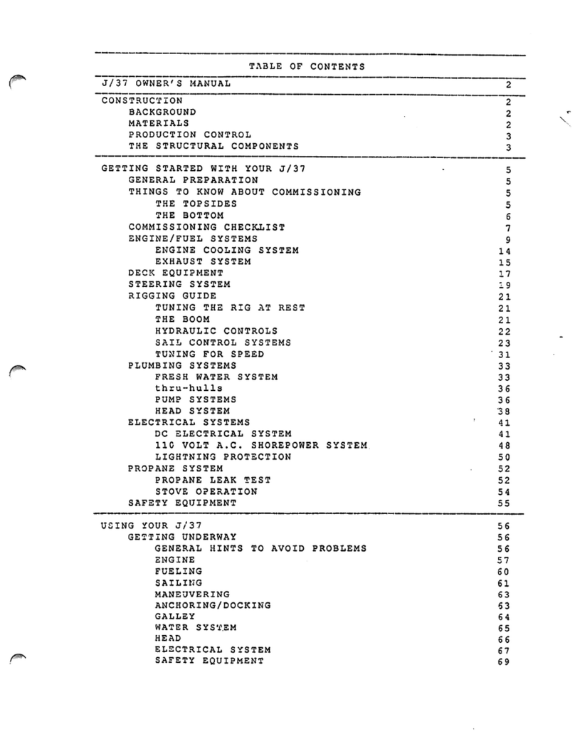
Table of Contents
Introduction........................................................................................................................................................................ 4
Specifications.................................................................................................................................................................... 5
Important Contacts........................................................................................................................................................... 6
Commissioning Checklist ............................................................................................................................................... 7
Getting Started With Your J/109...................................................................................................................................... 8
Diagrams, Layouts, & Schematics............................................................................................................................... 12
Deck Hardware Layout ................................................................................................................................................. 12
Mainsheet & Traveler Diagram..................................................................................................................................... 13
Adjustable Genoa Leads............................................................................................................................................... 14
Halyard Layout............................................................................................................................................................... 15
Reefing System Diagram.............................................................................................................................................. 16
Chainplate Tie-Rod System.......................................................................................................................................... 17
Steering System ............................................................................................................................................................ 18
Engine Layout................................................................................................................................................................ 19
Exhaust System Layout ................................................................................................................................................ 20
Fuel System Layout....................................................................................................................................................... 21
Thru-Hull Locations ....................................................................................................................................................... 22
Fresh Water System Layout......................................................................................................................................... 23
Sump Layout ................................................................................................................................................................. 24
Bilge Pump Layout ........................................................................................................................................................ 25
Main AC/DC Distribution Panel..................................................................................................................................... 26
DC Component Layout ................................................................................................................................................. 27
DC Wiring Schematic.................................................................................................................................................... 28
DC Battery Monitor........................................................................................................................................................ 29
AC Component Layout.................................................................................................................................................. 30
Galvanic Isolator............................................................................................................................................................ 31
Propane System Layout................................................................................................................................................ 32
Bonding System ............................................................................................................................................................ 33
Tuning The Rig ................................................................................................................................................................ 34
Engine System ................................................................................................................................................................ 35
Sail Drive........................................................................................................................................................................ 35
Fuel System................................................................................................................................................................... 35
Engine Cooling System................................................................................................................................................. 36
Exhaust System ............................................................................................................................................................ 36
Engine Safety Precautions............................................................................................................................................ 37
Fueling ........................................................................................................................................................................... 38
Engine Maintenance ..................................................................................................................................................... 38
Plumbing Systems.......................................................................................................................................................... 39
Fresh Water System ..................................................................................................................................................... 39
Thru-Hulls ...................................................................................................................................................................... 39
Pump Systems .............................................................................................................................................................. 39
Head System................................................................................................................................................................. 40
Electrical System............................................................................................................................................................. 40
DC Electrical System .................................................................................................................................................... 40
110 VAC Shorepower System ...................................................................................................................................... 41
Galley Stove LPG System.............................................................................................................................................. 42
Safety ................................................................................................................................................................................ 43
Maintenance Tips............................................................................................................................................................ 44
Annual Maintenance Checklist ..................................................................................................................................... 46
Storage Tips..................................................................................................................................................................... 47
TPI Composites Limited Warranty .............................................................See Warranty Package Included with Boat


J/109 OWNER GUIDE
4
Introduction
WELCOME ABOARD and welcome to the J/Boats family of owners. Your boat is designed and engineered to be
the strongest, best performing, easiest-to-use, and most comfortable sailing boat of its type.
Sailing involves risk, most of which can be minimized with advance planning and proper seamanship. The J/109
owner should become proficient in all aspects of handling the vessel under sail and power, and be well versed with
emergency procedures before undertaking any offshore passage. The owner is further responsible for any required
state registration or federal documentation, accident reporting, outfitting the vessel with proper safety equipment,
and the safe operation of the vessel. J/Boats is happy to refer the owner to Boating Safety Courses or other
seminars available.
This guide is prepared to help owners understand proper rigging, tuning, and operation of the J/109. Please be
sure to complete the enclosed warranty card and mail to TPI Composites, Inc.
This guide is furnished for your benefit, but shall in no way be construed as any sort of warranty or contract, express
or implied, creating any obligation on the part of J/Boats, Inc., with respect to any fact or facts or any advice or
opinions contained herein. The sole and exclusive warranty of the product is the TPI Composites, Inc. Warranty
described in the appendix hereto and on the Warranty Card furnished with the yacht. J/BOATS, INC. HEREBY
DISCLAIMS ANY AND ALL WARRANTIES, EXPRESS OR IMPLIED, INCLUDING ANY WARRANTY OF
FITNESS FOR A PARTICULAR PURPOSE OR ANY IMPLIED WARRANTY OF MERCHANTABILITY.

J/109 OWNER GUIDE
5
Specifications
LOA 35.25'
LWL 30.50'
Beam 11.50'
Draft
7.0' (std.), or 5.75' (opt.)
Ballast 3,900 lb. (std.), 4,300 lb. (opt.)
Ballast Type Cast lead strengthened with antimony
Displacement (std boat) 10,900 lbs.
100% Sail Area 644 sq ft
I 46.50'
ISP 49.60’
J 13.30'
P 43.25'
E 15.50'
Headstay Pin to Pin Length 48.23’ (14700 mm)
Recommended Step Location Center mast step slot around standard bolt location
Engine Yanmar27HP 3GM30SD (3-cylinder Sail Drive)
Fuel Capacity 23 US gallons
Engine Alternator Balmar 100 amp
Battery Capacity 210 amp hours (add'l 105 amp optional)
Battery Type AGM Glass Mat Batteries
Water Capacity 35 US gallons (std.) plus 35 gal. (opt.)
Interior Cabin Headroom
6.15’ (6’2”)
Limit of Positive Stability 124 degrees
LPG Capacity (1) 10 lb. Bottle
Hull & Deck Core Material BaltekAL-600 CK-57 End-Grained Balsa
Hull & Deck Molding Process SCRIMPResin Infusion
Hull Blister Warranty 10 Years: Owner Transferable
Mast Height Above Water 53.50' (not including masthead instruments)
Displacement/Length Ratio 165
Sail-Area/Displacement Ratio 21
ISO Stability & Bouyancy (CE Mark)
Category A
Recommended PHRF Rating 72

J/109 OWNER GUIDE
6
Important Contacts
J/Boats Inc. Phone: 401-846-8410
PO Box 90; 557 Thames St. Fax: 401-846-4723
Newport, RI 02840 Email: info@jboats.com
www.jboats.com
President Jeffrey S. Johnstone Email: jeffj@jboats.com
VP/Technical/Design R. Alan Johnstone alj@jboats.com
Sales Coordinator James M. Johnstone jimj@jboats.com
Office Manager Marilyn Murphy marilyn@jboats.com
PR Assistant Kendra Wilson kendra@jboats.com
Design: Rodney S. Johnstone Phone: 860-535-3480
PO Box 222 Fax: 860-535-3481
Stonington, CT 06378 Email: rodj@jboats.com
Marketing: Robert L. Johnstone Phone: 843-579-0902
7 Church Street Fax: 843-579-
9004
Charleston, SC 29401 Email: bobj@jboats.com
Factory: TPI Composites, Inc. Main Ph: 401-245-1200
PO Box 328; Market St. Service: 401-247-1050
RI 02885 Fax: 401-245-3160
www.tpicomp.com Email: custserv@tpicomp.com
Cushions: Alimar, Inc. Phone: 401-254-0439
116 Tupelo St. Fax: 401-254-6150
Bristol, RI 02809 Email: alimar94@aol.com
Spars/Rigging: Sparcraft/Charleston Spars Phone: 704-597-1502
3901 Pine Grove Circle Fax: 704-597-0961
Charlotte, NC 28206 Email: chssparsal@aol.com
Canvas: Thurston Sails (Neil Thurston) Phone: 401-254-0970
Tupelo Street Fax: 401-253-7830
Bristol, RI 02809

J/109 OWNER GUIDE
7
Commissioning Checklist
Pre-Launch
___ Read equipment owner manuals
___ Pre-rig mast and check installation of:
•halyards
•blocks
•electronics
•shrouds
•spreader chafe guards
•lifeline pins
___ Pre-rig boom
___ Bottom painted or touched up
___ Check propeller/zinc
___ De-winterize engine and check status of:
•engine oil/ filter
•coolant level
•transmission fluid level
•water intakes/filter
•fuel lines/filter
___ Check battery charge
___ Align prop vertically & mark shaft
___ Check all hose clamps, tighten as required
___ Close all seacocks
Loose Gear
___ Fenders and lines
___ Dock lines
___ Winch handles
___ Ignition keys
___ Bilge pump handles
___ Mast wedges/Spartite lubed
___ Double-check sling locations and mark
Launch
___ Check for leaks
___ Check seacocks
___ Check engine seal for leaks
Engine Start
___ Read engine owner’s manual
___ Align engine and shaft
___ Start engine
___ Check exhaust for cooling water flow
___ Check oil press., water temp., charging gauges
___ Check transmission- forward/reverse
___ Check transmission leg seal
Step Mast
___ Install pre-molded Spartite wedge onto mast butt
___ Locate table and mast step wood trim pieces
___ Hoist spar and lower into boat
___ As mast butt lowers into interior, slide on wooden table
trim and mast step trim pieces.
___ IMPORTANT!! Attach tie-rod from forward side of mast
to padeye on under side of deck and tighten.
___ Attach furler to stemhead fitting
___ Attach hydraulic cylinder to backstay and SS extender
___ Attach all shrouds and hand tighten
___ Run a bead of clear silicone around mast collar at mast
junction and collar junction.
___ Run and connect mast junction box wires
Rigging
___ Install boom
___ Lead all halyards to stoppers on cabin top
___ Rig reef lines
___ Install and connect boom vang
___ Rough tune spar per tuning guide
Systems Check
___ Fill water tank(s)- flush twice to eliminate anti-freeze
___ Check water pressure system, bleed air if necessary
___ Fill and check LPG system
___ Fill fuel tanks
___ Check operation of electrical systems and pumps
___ Check sailing electronics
Trial Sail
___ Raise and lower sails to check for fit
___ Monitor engine performance
___ Check bilge for leaks
___ Check sailing electronics
___ Mark locations in cockpit to install teak foot braces
(shipped loose)

J/109 OWNER GUIDE
8
Getting Started With Your J/109
Generally, your dealer or commissioning yard will help you prepare your boat before launching. And in most
instances they will undertake the entire commissioning job. They are experts in the field and are capable of
completing most commissioning tasks.
Before Proceeding
Before you begin to assemble your new boat you should become familiar with the different sail control
systems and associated hardware. All running rigging and loose deck hardware items are shipped from the
factory in parts boxes complete with part inventory sheets. To help you properly install these items please
refer to the rigging and hardware sections and diagrams in this guide.
The Commissioning Checklist: will help you double check that the J/109 is assembled properly and all
systems and rigging are functioning properly. If a boatyard other than an authorized J/Boat dealer is
performing the work, review this list with them to establish what needs to be done and by whom.
Topsides: wash off all dirt and grime accumulated from delivery. Use only non-abrasive cleansers on the
gelcoat. Then apply a coat of high quality car or boat wax or use a synthetic poly-based coating. Either
finish will prolong the life and sheen of the gelcoat.
Bottom: preparation is critical to long-lasting enjoyment. To ensure a professional finish, carefully review
the paint manufacturer’s recommendations for preparing the bottom and have your dealer roll it or spray it
on. Be sure that there are a MINIMUM of 4 coats of epoxy primer covering the keel and rudder prior to final
coating of bottom paint.
Chainplates: are machined of polished stainless steel. Each fitting is mounted to the deck and attached to
a tie-rod that anchors directly into the structural grid of the boat in the main salon. These fittings are pre-
tensioned at the factory. No changes or adjustments are to be made to these without specific authorization
from TPI Composites. The backstay chainplate through-bolts directly to a reinforced area of the transom.
Stemhead Fitting: is a custom polished stainless fabrication with integrated genoa tack loop. The stem
head fitting is designed to withstand all headstay loads, and is attached with bolts directly to the stem of the
hull.
Mast Collar: is a cast aluminum fitting and incorporates stainless pins for halyard and reefing line turning
blocks. A custom molded Spartite wedge fits between the mast and this collar. This wedge should be
installed into the boat with silicone at the interface with the mast collar and with the mast. The rubber mast
boot then fits over the flange of the collar to help seal the interior.
Foredeck Toe Rail: is molded into the deck on the J109 and extends from outboard of the mast forward to
the bow pulpit.
Stanchions & Pulpits: are designed for proper offshore safety as well as to facilitate access to the boat.
Included are two lifeline gates to port and starboard and a stern boarding gate. The bow pulpit is properly
braced, houses the bow running lights under the mid-height bar across the front end. The stern push-pit is
standard with an aft gate and stern running light. This is a convenient place to mount a man overboard
module, outboard bracket, etc.. All stanchions are 1” diameter tapered stainless steel and are secured into
their custom designed bases with machine set screws.
Lifelines: are SS wire in accordance with ORC safety regulations and are fastened at either end by
stainless forks and turnbuckles. Each lifeline is clearly marked from the factory and is intended to fit a
specific portion of the lifeline/stanchion system. The installation follows:

J/109 OWNER GUIDE
9
•Insert all lifeline gates/stanchions into the sockets provided along the edge of the deck. Secure each
stanchion in place by tightening the two set screws in each base. We recommend that you dip the
screws in blue Loctite or sealant before securing, so they don’t work themselves loose over time.
•Install all lifelines without tightening the turnbuckles. Remove the eyes at the ends of the lifelines and
thread them through in the stanchions. If the boat is equipped with the optional lifeline pads, thread the
lifeline through these prior to attaching to stern rail. The longer lifeline pad will be sized for the upper
lifeline and the shorter for the lower lifeline.
•Finish off the job by tightening the turnbuckles, adjusting the lifeline gate pendants for the proper length,
and taping off the turnbuckle “split rings” (or cotter pins) for a finished appearance.
•Aft Lifeline Tip: To protect the hydraulic cylinder handle from the wire lifelines, get a piece of snap-on
plastic lifeline coating from West Marine and cut two small 4” pieces and install one on the upper and
the other on the lower lifeline centered about the handle.
Skylight Ventilation Hatches: are made of extruded anodized aluminum frames and scratch-resistant
acrylic covers. Each hatch comes equipped with a ventilation position and 180 degree articulation and
screens.
Ports and Opening Ports: are of painted aluminum frames with bronze colored acrylic and arrive “ready-
to-use”. The opening ports are specifically engineered and located to maximize cross-flow ventilation
screens are also provided for each of the opening ports.
DO NOT PERMIT ACETONE OR OTHER HARSH CLEANSERS TO GET ON PORTS, OR HATCHES AS
THEY MAY DAMAGE THE FINISH & CLARITY OF SOME DECK HARDWARE.
Deckhouse Handrails: Stainless handrails are standard for easy maintenance and ownership.
Winches: Standard winches are aluminum self-tailing models from Harken Yacht Equipment. The location
of these winches facilitates sailing with one or two aboard. Each is geared to match the load requirements of
the specific task.
J/109 Steering System
The steering system is carefully engineered to provide finger-tip control. This is achieved by utilizing Edson
rudder bearings and steering system components. The pedestal is custom designed and incorporates
molded foot-rests, a Ritchie compass and additional instrumentation space on the stainless wheel guard.
Wheel: is a 54” Edson “Diamond” series aluminum wheel with a leather cover. The wheel is mounted to the
pedestal by through-bolting the hub to the stainless hub bracket. When installing, first center the rudder,
then install the wheel with the name plate vertical. Then place a mark at the top of the rim or on the vertical
spoke as a centerline reference point.
Rudder: is made of unidirectional glass, with two halves bonded together, and a highly reinforced fiberglass
shaft that extends to 80% of the depth of the rudder. The rudder is engineered to withstand tremendous
shear loads in ocean conditions. The high aspect shape helps reduce the “torque” tendency of most
rudders, thereby reducing helmsman and auto-pilot fatigue.
Rudder Stock Stuffing Box: is located at the top of the fiberglass rudder tube beneath the decks. It is a
simple design that prevents water from entering the hull. A stainless sleeve bearing surface surrounds the
rudder shaft at the point where a rubber seal is forced against it to prevent water from rising up the tube.

J/109 OWNER GUIDE
10
Emergency Tiller: is operated by lifting off the access plate (amidships), and placing the base of the tiller
over the head of the rudder stock. Rudder is rotated using the T-shaped handlebars. Fit the emergency
tiller NOW to see how the system works BEFORE you get caught in a situation where you won’t have the
time!
J/109 Rigging
The running and standing rigging items supplied with your boat are designed for efficiency. A wealth of
racing and cruising experience has gone into the deck layout to make sailing and boat handling safe and
easy to handle by a couple and for a racing crew.
The most unique system on your J/109 is the bow sprit system for the asymmetric spinnaker. We believe
this system is a major improvement over conventional systems and so let's start by explaining how it works.
•Carbon Fiber Bow Sprit: The carbon fiber bow sprit is custom made by Advanced Composites and is
designed to withstand the loads associated with the asymmetric spinnaker without any additional
support. The pole consists of a carbon tube finished with two molded end fittings. The forward end
fitting has a "U" bolt which serves as the attachment point for the tackline block. The aft end fitting
houses all hardware necessary for the adjuster line and shock cord retrieval system.
•Bow Sprit Launching Line: The control line to pull out the bowsprit is designed to be adjusted without
leaving the cockpit. The line is dead-ended to the inboard pad eye on the forward most bulkhead in the
forepeak. The line then leads through the thru-pole blocks on the aft end fitting of the carbon fiber pole
(be sure the "U" bolt on the other end of the pole is up), forward through a block on the outboard
padeye on the forepeak bulkhead, then through the stainless handrail in the main salon, through the
head, and finally to a cam cleat mounted on the aft side of the cabin top to starboard.
•Harken Headsail Furling: A standard Harken Furler is provided with the boat and requires assembly
prior to installing the mast. A complete instruction manual is included with this hardware detailing the
procedure. The pin-to-pin headstay length necessary to complete this task for the J/109 is 14700mm or
48’2-7/8”.
•Mast: Rigging the J/109 mast is a common procedure, and best handled by a qualified marine rigger.
All spreaders, shrouds, and halyards are installed and properly taped and secured. The masthead
anchor light and the steaming light are shipped loose with the J/109 Sparcraft mast to prevent damage
during shipping. Be sure these and all other mast related electronics and wind indicators are properly
wired and installed prior to stepping the mast. After stepping the mast it is VERY IMPORTANT to install
the wire fitting from the forward face of the mast in the interior up to the underside of the deck and
tighten prior to going sailing. We also recommend that a small cord is tied and taped approx. 24” above
each lower spreader between the intermediate shroud and upper shroud. Simply tie this line to each
shroud (allowing for some slack) and tape ends over with rigging tape. This prevents the asymmetrical
spinnaker (during a take down) from potentially dropping into the V that is formed at the lower spreader
between these shrouds.
•Hydraulic Backstay: The J/109 is equipped with an integral hydraulic backstay to help you fine tune your
rig and sails for optimum performance. This hydraulic unit is simple to operate, easy to maintain, and
highly reliable. The cylinder is affixed at its lower end to a stainless backstay extension rod that
attaches to the tang on the transom and at its upper end to the eye at the end of the backstay. In order
to make the cylinder fit, you must release the hydraulic valve and pull out the SS shaft and fully extend
it.
•Boom: Run the reef lines so the red line (port) is led through the port sheaves and the green line
(starboard) is led through the starboard sheaves at both the outboard end and the gooseneck. The
starboard reef doubles as the cunningham.

J/109 OWNER GUIDE
11
•Boom Vang: The Hall QuikVang is a mechanically operated spring loaded boom vang with a Harken
block and tackle purchase system. This vang system allows for quick and easy adjustment and also
acts as a boom topping lift. The vang is affixed to the vang plate welded underneath the boom and to
the mast at the vang gooseneck located just above the mast collar. See the QuikVang operating
instructions for how to adjust the internal spring for best results.
Sail Control Systems
After stepping the mast and connecting the boom, QuikVang, Harken furler, and integral backstay, rig all
halyards and the remaining sail control systems.
•Main Halyard: exits the mast on the port side, runs through a turning block at the mast collar, through
the inboard port organizer block and then aft through the port double stopper (inboard hole) and finally
to the halyard winch. The tail end is stored in a supplied line bag to be mounted outboard and forward
of the stopper.
•Jib/Genoa Halyard: exits the mast to port, leads through the forward mast base block, aft to the
outboard sheave on the organizer block, through the outboard stopper hole, and store tail in line bag.
(additional jib/genoa halyard option leads to starboard).
•Spinnaker Halyard: exits the mast to starboard and leads to the outboard sheave and stopper.
(additional spinnaker halyard option leads to port).
•Mainsheet Traveler: is a Harken low friction system. The 4:1 purchase system on each side controls a
Harken Car mounted on midrange track (see diagram).
•Outhaul: is adjusted at the cleat on the underside of the boom and comes pre-assembled.
•Cunningham: The cunningham doubles as the starboard reef line. To set it up as a cunningham
simply tie a knot at the boom end tail of the reef line. The line leads forward to the sheave at the
gooseneck, up to the cunningham block with S.S. hook back down through a bullseye on the mast,
down to the mast base block and aft to the inboard stopper.(see diagram). To use the continuous reef
system simply run the boom end tail through the clew reef grommet, back down around the boom and
tie a bowline.
•Mainsheet: is a 24:1 system with a 6:1/4:1 set-up (see diagram). The system is designed to allow easy
adjustments of the mainsheet. The location of the traveler also facilitates single-handed sailing and
adjustments. The fixed centerline cleat base rotates to port and starboard for a proper lead. Be sure to
put a "stopper knot" like a figure-eight at the end of the mainsheet.
•Jib/Genoa Sheet: attaches to the roller-furler headsail by a simple knot, leads to the jib/genoa block on
the track, aft to the turning block on the cockpit coaming and then to the primary winch.
•Spinnaker Sheets: lead from the clew of the spinnaker aft outside the lifelines through the spinnaker
sheet blocks turning forward to a fairlead block mounted on the padeye along the rail and then into the
primary cockpit winches or secondary cabin top winches.

J/109 OWNER GUIDE
12
Diagrams, Layouts, & Schematics
Deck Hardware Layout

J/109 OWNER GUIDE
13
Mainsheet & Traveler Diagram

J/109 OWNER GUIDE
14
Adjustable Genoa Leads

J/109 OWNER GUIDE
15
Halyard Layout

J/109 OWNER GUIDE
16
Reefing System Diagram

J/109 OWNER GUIDE
17
Chainplate Tie-Rod System
The J/109 Chainplate Tie-Rod system is installed at TPI Composites and shall not be tapered with unless
specifically authorized by TPI (Phone 401-247-1050). The tie-rod itself is assembled into the Trunnion using
a non-permanent Loctite and brought up to a factory specified torque setting. No additional adjustment
should be needed as any further tension may deform or crack the deck. The Tie Rod is not designed for
and shall not be used to adjust rig tension or tuning.
The illustration above is an exploded isometric view of the Tie Rod Assembly. The Tie Rod is not shown at
its full length. When assembling the Screw In Cap to Chain Plate the same non-permanent Loctite is to be
used.

J/109 OWNER GUIDE
18
Steering System

J/109 OWNER GUIDE
19
Engine Layout

J/109 OWNER GUIDE
20
Exhaust System Layout
Other manuals for J/109
2
Table of contents
Other J/Boats Boat manuals

J/Boats
J/Boats J-33 User manual

J/Boats
J/Boats J/160 User manual

J/Boats
J/Boats J/109 User manual

J/Boats
J/Boats 70 User manual

J/Boats
J/Boats J/70 User manual

J/Boats
J/Boats J37 User manual

J/Boats
J/Boats J 35 User manual

J/Boats
J/Boats J/111 User manual

J/Boats
J/Boats 130 User manual

J/Boats
J/Boats J/44 User manual
Popular Boat manuals by other brands

Skier's Choice
Skier's Choice Moomba Series 2019 owner's manual

Jilong
Jilong Z-RAY I 200 instruction manual

Rangertugs
Rangertugs R-31 Series owner's manual

Rangertugs
Rangertugs R-23 owner's manual

PURSUIT
PURSUIT 1950 Center Console owner's manual

Key West Boats
Key West Boats Family Sportsman Series Quick guide and schematics