J D Squared Model 54 User manual

JD Squared Inc.
2244 Eddie Williams Rd.
Johnson City, TN 37601 USA
(423) 979-0309
Copyright 2014 by JD Squared Inc.
Model 54 Bender
Assembly and Operating Instruction Manual
Revision Date: 4/28/2015

Table of Contents
Uncrating ���������������������������������������������������������������������� 3
Assembly ���������������������������������������������������������������������� 4
Moving the bender.......................................................................................................................................... 4
Installing the handles...................................................................................................................................... 4
Floor mount or wheeled?................................................................................................................................ 4
Wheeled installation ....................................................................................................................................... 4
Floor mounted installation .............................................................................................................................. 4
Leveling the spindle........................................................................................................................................ 5
Filling the hydraulic oil tank ............................................................................................................................ 5
Electrical connection....................................................................................................................................... 5
Assembling the toggle mechanism................................................................................................................. 6
Adjusting the toggle mechanism’s over-center distance ................................................................................ 7
Tool Plate Installation ������������������������������������������������������������ 8
Loading the Die Set and Adjusting the Toggle ���������������������������������������� 9
Rotate spindle to its start position................................................................................................................... 9
Installing the forming die onto the spindle ...................................................................................................... 9
Installing the U-strap....................................................................................................................................... 9
Description of the pressure die assembly..................................................................................................... 10
Installing the pressure die into the bender.................................................................................................... 10
The main operating principle of the Model 54 bender .................................................................................. 11
Adjusting the toggle mechanism for bending................................................................................................ 11
How to make a bend and remove the work piece when nished ................................................................. 12
Spindle lock operation .................................................................................................................................. 12
Computer Operation ������������������������������������������������������������ 13
Computer modes .......................................................................................................................................... 13
Program selection mode............................................................................................................................... 13
Operation mode............................................................................................................................................ 13
How to Calculate the Correct Bend Angle������������������������������������������� 13
Maintenance������������������������������������������������������������������� 14
Setting the spindle to zero ............................................................................................................................ 14
Exploded view of spindle components ��������������������������������������������� 15
Installing the Encoder ................................................................................................................................... 16
Encoder components ����������������������������������������������������������� 16
Bending Tutorial Using Template Bends ������������������������������������������� 17
Uncrating
Parts included with bender:
1 Pressure screw pin (1” diameter)
1 U-strap pin and hitch pin clip (7/8” diameter with multiple
drilled holes)
1 Die socket set screw (3/4”-10 x 3.5” long)
1 Die washer (3/4” hole)
1 Die nut (3/4”-10 hex)
2 1/2”-13 x 2 1/2” long leveling bolts
2 1/2”-13 hex nuts
4 1/2” washers
1/2” leveling bolts
Bender’s crate with sides and top removed.
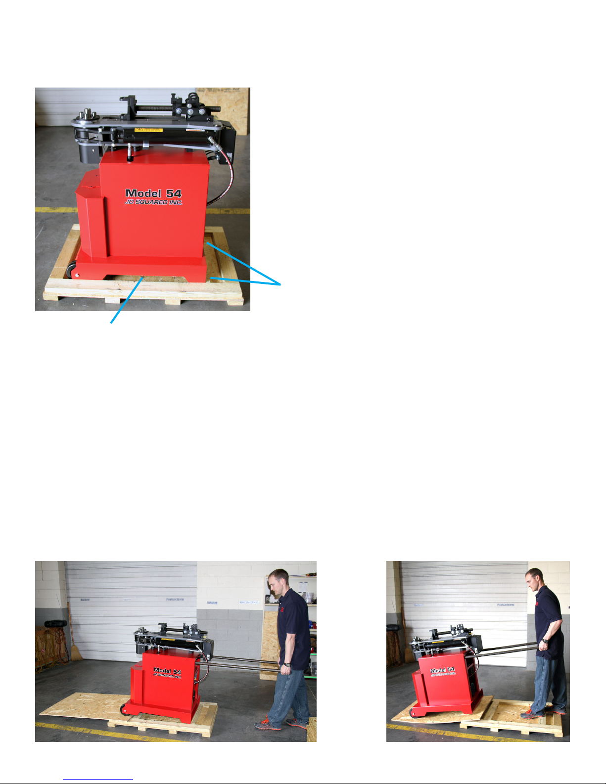
1) Remove the top and sides from the crate. Remove the 1/2” bolts attaching the bender to the crate’s oor but
do not discard them. They are used later to level the rear of the bender.
2) Removing the bender with a forklift: The bender may be lifted from the base using a forklift by inserting
the forks into the forklift access slot as shown in the above picture. The forks should be spread out as far as
they will go and still t into the slot. The bender is very top heavy and you must be careful not to let it tip and
possibly fall off the forks. We recommend you use tie downs and strap it to the forks. Also, make sure no one
is around the bender that may be hurt if the bender falls off the forks. GO SLOW AND BE VERY CAREFUL.
Removing the bender without a forklift: The bender may be rolled off the base using the procedure shown
below. In order to do this you will need to obtain 2 handles and a some 9/16” or thicker plywood. See the
section “Installing the handles” in the assembly section of these directions. Do not use the wood from the
crate’s side and top because it may not handle the bender’s weight.
1) Insert the handles and tilt the bender back. Place the plywood as shown below.
2) Carefully and slowly roll the bender down the ramp.
Forkli access slot
Page 3

Moving the bender
In order to save you money, the bender is sold without the
moving handles. Why? The 5 1/2 foot long handles will not t into
the bender’s crate and therefore must be shipped separately at
an average cost of over $40. The handle material itself however
is less than $10.
Installing the handles
Obtain 2 pieces of 1” pipe or 1 1/4” tubing at least 5 1/2 feet
long. Insert both handles into the 2 outer holes as shown to the
right and push them past the 2 inner holes until they bottom out.
Now you can easily move the bender around.
Floor mount or wheeled?
In order to achieve best results, the spindle must always be
as level as possible. To illustrate the problem, let’s assume the
bender is wheeled into position but the oor is 1ooff level from the horizon. The operator makes a 90obend.
Now the operator repositions the tube for the second bend and carefully levels the tube to the horizon and makes
the second bend. This repeats for a third bend. The result will be the rst and the last bend are now 2ooff plane
from each other. We refer to this as cork screwing. Therefore, the best way to setup up the bender is to mount it
directly to the oor as described later.
Wheeled installation
While oor mounting is denitely the best way to go sometimes the bender must be mobile. In this case, locate
the 1/2” bolts, nuts and washers you removed when uncrating the machine. Refering to the photo above, install
them back into the same holes in the base from where you previously removed them. The head of the bolt must
face down. The two bolts can now be used to level the bender.
Floor mounted installation
Remove the front wheels. Using the holes in the stand or the measurements below, mark the oor at the 4
corners of the bender’s stand. Now drill the holes and cement 1/2” threaded rods into the oor. Using 3 pairs of
nuts and washers at each corner, level the spindle’s top as described in the next section. Because the stand’s
welded dimensions may vary slightly from the drawing, verify the holes in the oor match the one’s in the bender
before cementing in the threaded rods.
Assembly
Bender shown with handles and the two rear
leveling bolts installed.
Page 4
Front corner, wheel removedBender mounted to oor
25.25
21.5
FRONT
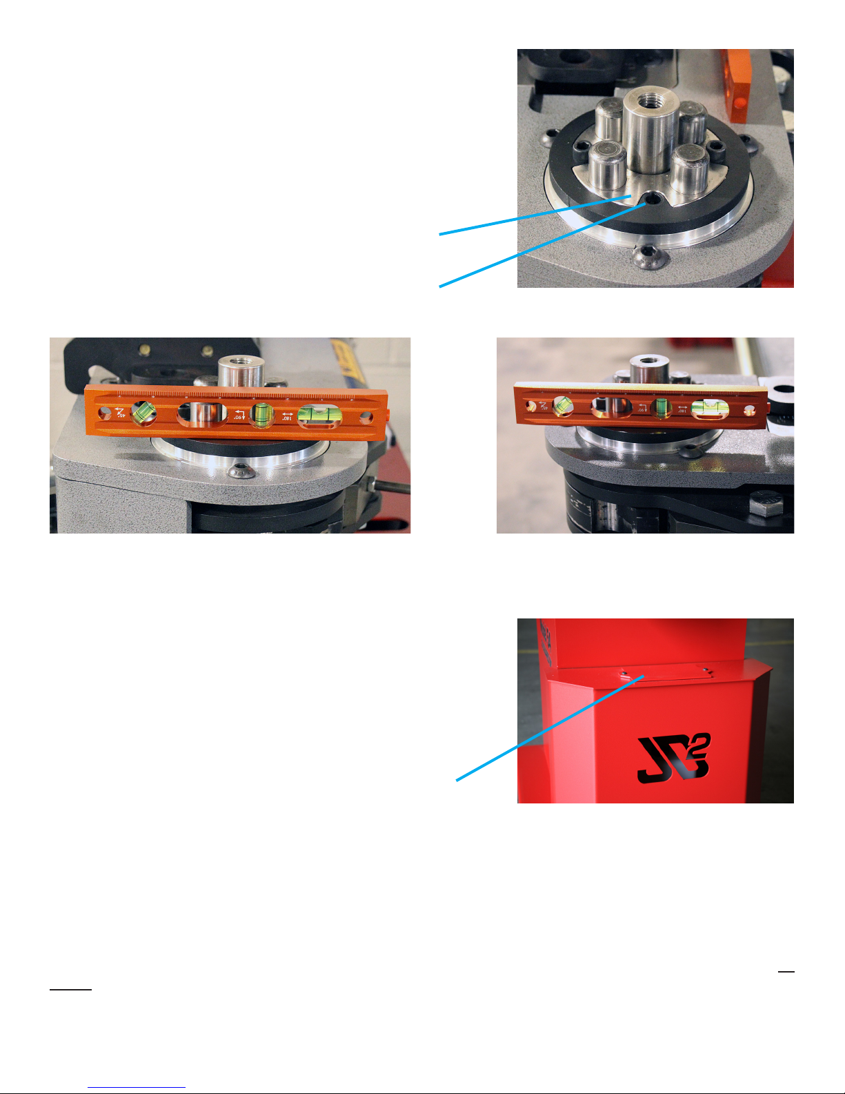
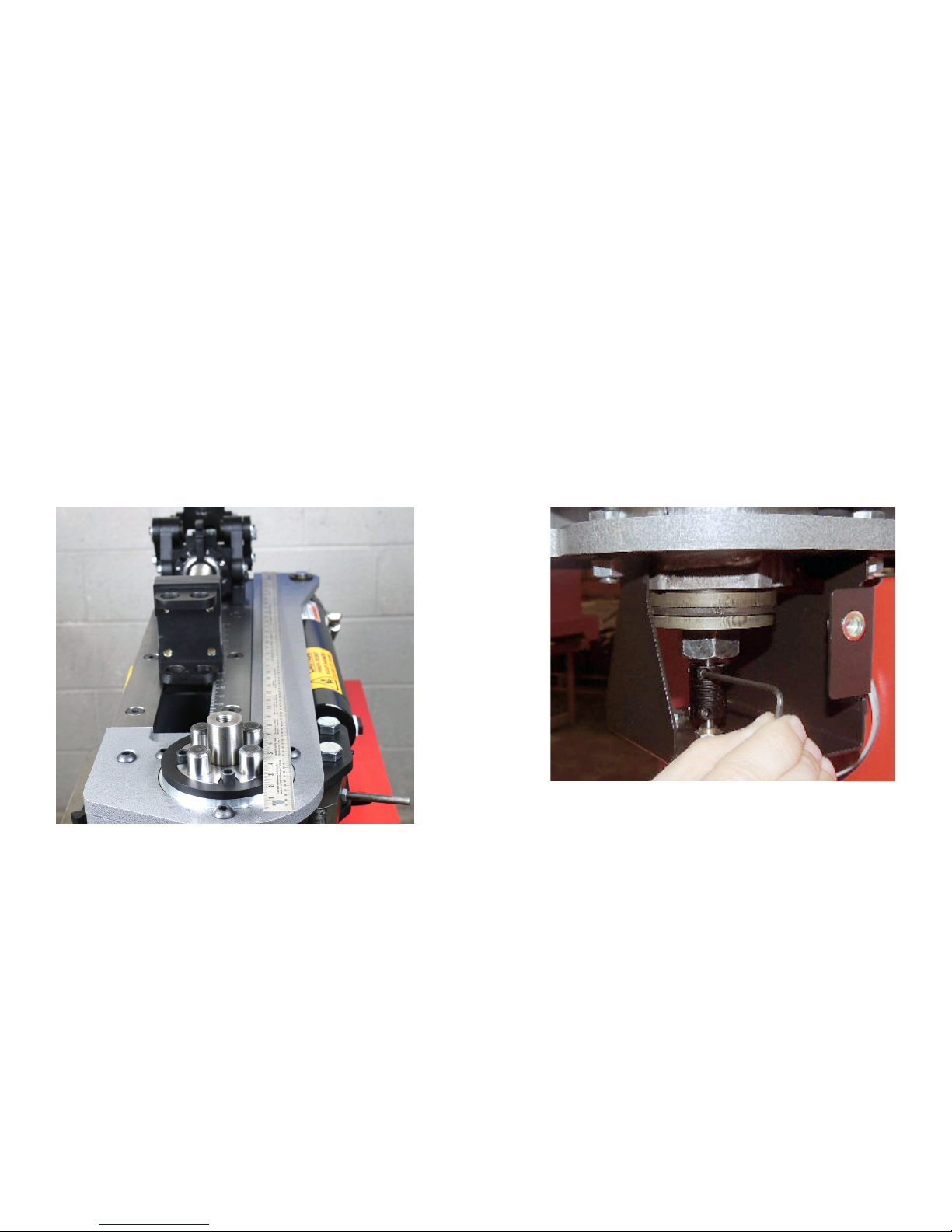
Leveling the spindle
1) Remove 1 of the 4 socket head cap screws from the top of the
spindle as shown to the right.
2) Place a level on the spindle’s upper surface. Do not place it
anywhere else such as the top of the screws or dowel pins
because they may not be level themselves.
3) By rotating the spindle 90ofrom the front to the side and adjusting
the nuts at the 4 corners, level the spindle as accurately as
possible.
Spindle rotated in order to level front to backSpindle rotated in order to level side to side
Leveling surface
Socket head cap screw removed
Filling the hydraulic oil tank
The bender is shipped without hydraulic oil as per transportation
regulations. Remove the front oil tank access cover. Using commonly
available ISO-32 or ISO-68 hydraulic oil such as used in agricultural
equipment, ll the oil tank to approximately 1” from the top. The
tank’s oil level may be seen easily through the JD2 logo using a
ashlight. A rubber hose attached to a funnel makes this job fairly
easy.
Oil tank access cover
Electrical connection
AC SUPPLY VOLTAGE: The bender may be congured to operate on an AC supply voltage of either 110-120v
or 220-240v. The solenoid installed in the bender must match the supply voltage to the bender. The standard
motor may be wired for either voltage.
EXTENSION CORD: If you plug the bender into an extension cord, we recommend you use the shortest 10
gauge cable possible. If you use a long cable, such as 50 feet or more, or a smaller gauge cable, the power drop
through the cable may be signicant enough to trip the breaker in your building’s fuse box. The pump may also
not receive enough power to develop full pressure.
Oil tank viewed through the JD2 logo
Page 5
Empty screw hole
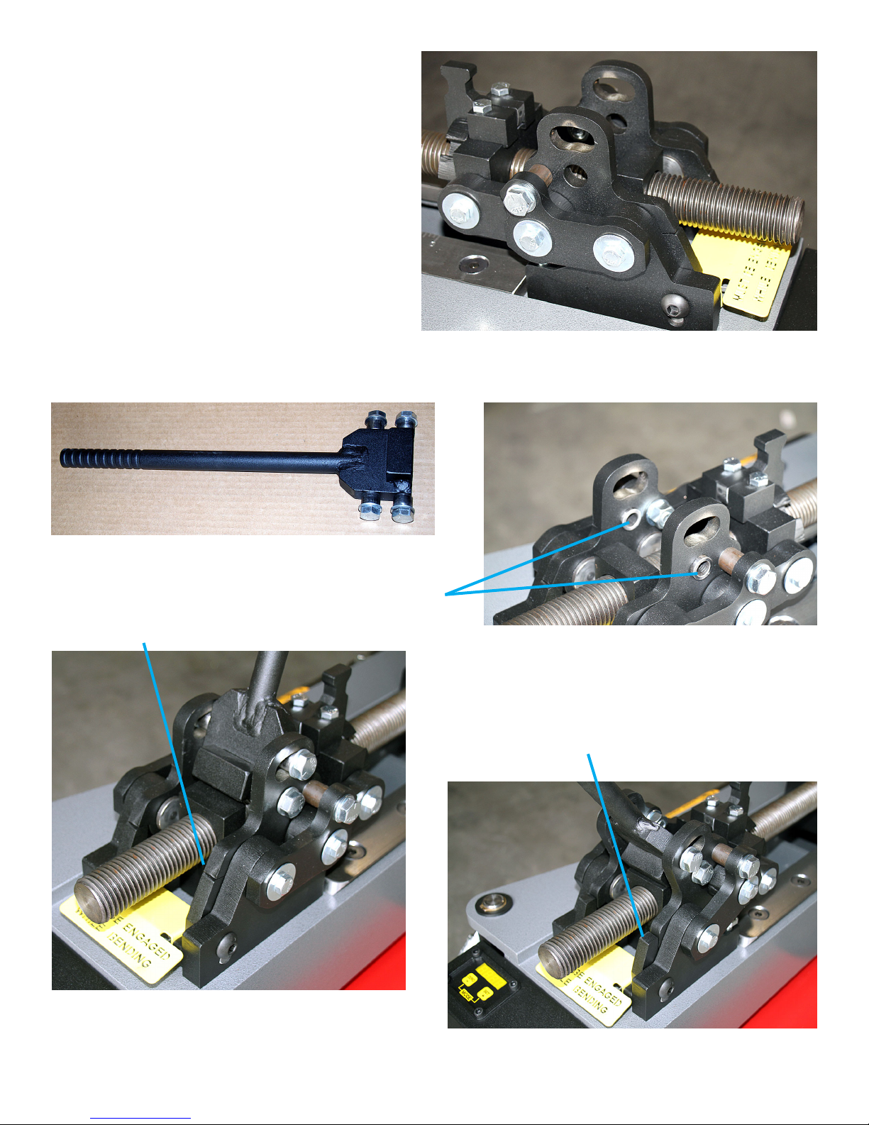
Assembling the toggle mechanism
1) Remove the bolts, washers and sleeves from
the handle.
2) Refering to the photo to the right, locate the 2
empty slots and holes. Place a sleeve in each
one of the 2 lower holes as shown.
3) Install the handle with the welded block to
the rear of the bender using the 2 bolts and
washers.
4) Install a sleeve in each slot. Install the remaining
2 bolts and washers into these sleeves.
5) Tighten all the bolts in the entire mechanism
very securely.
6) Verify the toggle moves freely and the safety
bar engages and disengages smoothly.
Toggle mechanism as shipped without the handle installed
Page 6
Sleeves placed in the lower 2 holes
Handle as shipped with bolts,washers and sleeves
Safety Bar Disengaged
Safety bar in the
disengaged position
Safety bar in the
engaged position
Sleeves
Safety bar engaged and all bolts have been installed
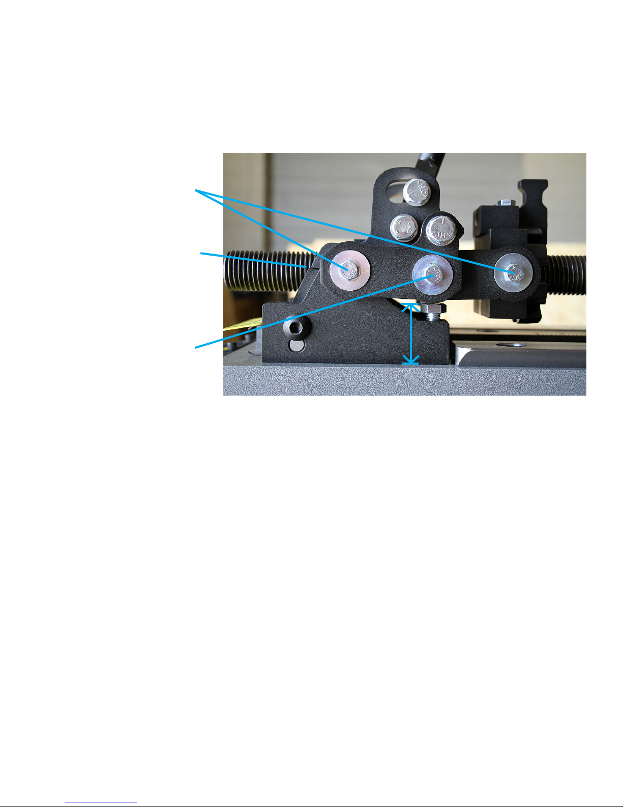
Adjusting the toggle mechanism’s over-center distance
The proper adjustment of the toggle mechanism is critical for the safe operation of the bender. The principle of
the toggle mechanism is that when engaged the middle pin will be slightly below the outer pins when the bender
is under load. This creates an over-center condition thereby preventing the toggle from disengaging when in use.
The distance that the middle pin is adjusted below the outer pins when engaged determines how difcult it will
be to disengage the toggle mechanism after the bend is complete. The dimension of 2” at the top of the adjuster
bolt is the factory setting. This will position the middle pin .050” below the outer pins when fully engaged. If the
toggle is ever disassembled, upon reassembly it must be readjusted to these values on both sides.
A small gap must be present
when the toggle is fully engaged.
Typically around .015-.030”.
is allows the safety bar to be
disengaged easily.
2”
49.5mm
Outer toggle link pins
Middle toggle link pin
Toggle mechanism’s side view
Page 7

The Model 54 has been designed to allow new tooling to be easily added in the future. This is accomplished
by using a tool plate that bolts to the pressure screw block. Various tool plate’s are available depending upon
the application. The majority of die sets use the standard 2 hole tool plate that is included with the bender. This
plate accommodates dies for up to 2.5” tube and 2” pipe. However, a die set such as 3” o.d. tube may require
a different tool plate. The correct tool plate for a particular die set can usually be determined by examining the
tooling and looking for the engraved markings such as shown below.
The dovetailed tool plate design was added
to the Model 54 in April of 2014. Therefore, if
the bender was purchased before that date it
may not have the upgrade installed. If this is
the case, please call our sales deptartment.
We feel this is a signicant improvement to
the bender and therefore offer this as a FREE
upgrade.
When the bender is under load, the dovetail
in the tool plate will suck down onto the outer
rail’s dovetail and lay at. This ensures the
tool plate’s pin holes are vertical and are not
tilted. It is CRITICAL that the tool plate and
the outer rail’s dovetailed surfaces are in full
contact under load.
To verify this, use the following procedure.
Without any tooling in the bender, push the
tool plate to the left towards the cylinder and try to raise the right side nearest the outer rail. If it does not tilt
towards the cylinder or try to lift then everything is ne. If this is not the case, there is not enough clearance
between the inner rail and the pressure screw block’s left side slot. This should only happen when a older bender
is being upgraded. To remedy this you can remove the pressure screw and using the edge of a le, remove
material from the bottom of the left slot until a clearance of .010” or slightly more is obtained. This can be seen
in the lower right photo. The amount of material to remove is usually only about .020-.030”. If you wish you may
also send the pressure screw to the factory and we will be happy to mill the slot deeper for free.
Tool plate
Outer rail Inner rail
Pressure screw block
Tool plate’s rear viewTwo hole tool plate’s front view Outer rail
Tool plate’s dovetail
must fully contact
the rail.
e engraving on the
tooling shows which
adapter to use.
Tool Plate Installation
If necessary
le here
when
upgrading
bender
Pressure screw block
Page 8
Must have .010” or
more clearance here
under load.

Rotate spindle to its start position
1) Retract the ram until it stops moving and then move it
forward slightly. If left fully retracted, the ram will pull the
spindle to the rear and lock it up. This does not harm
anything, it just won’t let you rotate the spindle by hand.
2) The drive hub has 7 teeth. One of them is much larger than
the others. This is the rst tooth. Pull the spring loaded
drive pawl’s handle out and rotate the spindle until the
drive pawl engages this tooth. This is shown to the right.
Installing the forming die onto the spindle
1) Examine the spindles upper surface and remove any debris
that may not allow the forming die to sit at. Also make
sure the four large 1” dowel pins are seated completely.
2) Install the forming die with it’s u-strap towards the cylinder.
Install the die washer and nut. Tighten securely.
Installing the round tube/pipe U-strap
1) Wipe the forming die’s groove clean. Never lubricate the groove as this would allow the tube to easily slip
during bending. Place the tube into the groove’s die.
2) Install the u-strap and insert the u-strap pin. The u-strap uses a clip pin to limit how far down the pin goes into
the u-strap. It is very IMPORTANT that you place the clip pin into a u-strap hole that allows the u-strap pin to
protrude past the u-strap’s lower surface by a 1/4” or more without the possibility of the pin hitting the spindle
button head bolts or the frame while rotating. This is shown in the picture to the lower right.
3) If bending thin wall tubing (.065” or less) you may need to tighten the
u-strap lock bolt to help prevent the tube from slipping backwards into
the die while bending. If the bolt tries to mar the tube, make a small
piece of curved metal and place it between the bolt and the tube.
Loading a Round Tube/Pipe Die Set
Drive hub’s 1st tooth Drive pawl
Forming die
Spindle top view. U-strap block
U-strap pin must extend past u-strap’s
lower surface by a 1/4” or more
U-strap pin must clear
the button head bolts as
shown here
U-strap lock bolt
1” dowel pin
Button head bolt
Page 9
Die Washer
and nut
NEVER lubricate the
forming die’s groove
U-strap pin and clip pin

Description of the pressure die assembly
The pressure die is shown in the 2 pictures below. It is sometimes referred to as a ‘followbar’. It constrains
the outside of the tube while bending. It is made up of 2 inserts and the backing block. The inserts are cast and
machined from a special, scratch and wear resistant, metal alloy. The inserts are relatively self lubricating but
are considered as consumable. They are NOT aluminum. Their typical life span is 1,000s of bends when using
clean tubing.
In the left side picture you can see the left insert is in line with the backing block and the right insert is angled.
The angled insert is the trailing insert and will always be closest to the u-strap during bending. It rides where the
tube has already been bent, thus helping to minimize the amount of attening on the outside of the bend. It is
computed to within 1/1000th of a degree at the time of manufacture to produce the best bend conditions for the
size of tubing and the bend radius. Therefore, the pressure die must be installed into the bender correctly in order
to take advantage of this design feature or you will experience poor bend quality.
In the right side picture you can see the bottom of the pressure die. The roll pin will hold the pressure die up
when the pressure screw is retracted. It must be adjusted so that the insert’s grooves are 1/16” or so below the
forming die’s groove when the tube is not loaded. This will allow the pressure die to rise slightly and level itself
when the toggle is advanced into the bending position.
The standard tool plate has 2 pin hole locations. This allows the amount of rear insert force to be tailored to
the tube being bent, thus producing a better quality of bend.
Installing the pressure die into the bender
If you examine the pressure die’s top surface you will notice the engraved word TOP and usually a circle and
tool plate outline. This engraving illustrates which tool plate is needed and what hole to place the 1” pin into.
Place the pressure die into the tool plate and align it with the engraved markings aligned with the tool plate’s
outline. The lower left picture shows a pressure die designed for the standard 2 hole tool plate. The 1” pin
obviously goes into the hole on the right side of the photo. Always be very careful to ensure the 1” pin as been
completely seated all the way down to the roll pin.
The 3” tube pressure die shown below right is designed for a 1 hole tool plate as can be seen by the engraving.
Pressure
die insert
Pressure die top view Pressure die bottom view
Roll pin
Engraved phantom
hole circle and TOP
indicator
Backing
block
A pressure die installed into a two hole
tool plate.
e engraved outlines
show how to load the
pressure die
Page 10
Angled insert
A 3” tube pressure die. It is designed for a one hole tool
plate as can be seen by the engraving.

Installing the forming die onto the spindle
Install the square groove forming die onto the spindle exactly as described in the previous section about
installing a round groove die.
Installing the square groove tube clamp
Loading a Square/Rectangle Tube Die Set

The Model 54 has been designed to make it easy to obtain repeatable bend angle. You do not need to worry
about springback calculations, mechanical tolerances and so on. The bender doesn’t even need the computer to
home the spindle upon powering on.
The main operating principle is simple. Where does the spindle need to rotate to in order to achieve the
desired degree of bend? It seems obvious, but how is this accomplished?
A key feature of the Model 54 is that it uses an absolute position encoder on the spindle. It has been factory
set to read zero when the spindle is rotated to the start position. When the spindle is rotated to any arbitrary
position, even if the bender was previously turned off and back on, it will always display the same value within
the encoder’s .1oerror range.
The other key principle is that the toggle mechanism must ALWAYS
be set to the EXACT same position every time a particular die set is
used. Before we explain further, it will be much easier to understand if
you learn to adjust the toggle mechanism as described next. After that
we will continue.
Adjusting the toggle mechanism for bending
When the toggle mechanism has been properly adjusted, the tube
will protrude straight out the back of the bender at 90oto the frame
during bending. Follow these steps to accomplish this.
1) Load the die set, tube and u-strap components as described earlier.
2) Install the pressure die as also described earlier.
3) Lift the index wheel lever to disengage it from the slot.
4) Push the pressure die forward until it wraps over the tube completely
as shown in the picture in the upper right.
5) Push the toggle lever to the full forward locked position. The safety
bar will engage. Note, you may need to unscrew the index wheel to
achieve this.
6) Adjust the index wheel to the rear of the screw as far as it will go.
7) Pull rearward on the right side of the tube as shown to the right. If
the tube does not stop at 90oto the frame, push the pressure die
forward again and readjust the index wheel a little further rearward.
Disengaging the toggle to the rear position makes this much easier.
8) When you’re satised, lower the index wheel lever into the nearest
slot.
9) For this particular die set you should ALWAYS return the pressure
die to this EXACT setting every time it is installed. We recommend recording the below setting as 8.3.7 and
then stamp it into the top of the die. The 8 is the major number from the side scale as shown in the below left
picture. The 3 is the number of WHOLE increments past the 8 and the 7 is the slot used in the index wheel
as shown below and to the right. It may appear we’re at 8.4 but in reality the reading is slightly less because
the wheel has 8 slots and we’re all the way to slot 7, just shy of the 4th increment.
Pressure die pushed onto the tube.
Side scale shown at 8.3 Index wheel shown at slot 7
Index wheel lever
Index wheel set
to slot 7
Side scale
reading 8.3
Pulling tube rearward
Page 11
Adjusting the Toggle Mechanism

Striking the tube’s end Toggle in the disengaged posyion
How to make a bend and remove the work piece when nished
1) Load the tube to be bent and adjust the toggle as described earlier.
2) Lubricate ONLY the outside of the tube where the pressure die slides.
Do NOT oil the groove. Cooking spray works surprisingly well here.
3) Verify the pressure die’s 1” pin is all the way down and extends below
the lower plate. Verify the u-strap pin extends below the u-strap by a 1/4”
or more and will not hit the button head bolts or frame during bending.
4) Stand well clear of the toggle lever’s ENTIRE range of travel. Injury may
result in the extremely unlikely event the lever snaps back under load.
5) Press the ram advance button on the pendant to start bending.
6) Upon completion, retract the ram a few seconds to relieve the bending
pressure. Most of the time the tube will come loose by itself. However,
you may hit the rear of the tube as shown below to help dislodge it.
7) Press the safety bar down and retract the toggle lever. You can now remove the tube.
Spindle lock operation
When activated, the spindle lock will engage at 22.5ointervals
to prevent the forming die from rotating counter-clockwise. This
is necessary if for any reason the bend process must be stopped
and the cylinder is retracted such as making a 180obend. If the
spindle is allowed to rotate backwards the pressure on the tube
relaxes allowing the tube to lift slightly in the die groove. This can
cause problems when the bend is continued. It is the main cause
of wrinkling thin wall tubing (.065” or less). The tube may also slide
backwards in the die making it very difcult to obtain accurate
bends.
The spindle lock is not needed for bends up to 90obecause a
single stroke of the ram advances the spindle approximately 115o.
To disengage it, push the lever forwards as shown to the right. For
bends greater than 90ouse the procedure below.
1) Engage the spindle lock by moving the lever to the rear position
as shown to the right.
2) Press the pendant button and start bending. Every 22.5oyou will
hear the spindle lock click into the locked position. You can also
see the lever moving back and forth as the bend progresses.
At approximately 90oof bend you will hear the spindle lock
engage again. Immediately stop bending. Try to stop the
bender as close as possible after the lock has engaged.
3) Retract the ram until the drive pawl engages another tooth. If
you retract it all the way to its start position, a full 180obend
can be made with only two shots of the ram.
4) When the bend is complete, move the latch to the forward position to disengage the spindle lock.
5) You can now remove the tube is described in an earlier section.
e spindle lock in the disengaged position.
e spindle lock in the engaged position.
Pressing the advance button
Page 12

Page 13
Computer Operation
Computer modes
The computer has only 2 modes, the program selection mode and
the operation mode. In the program selection mode the display ashes
between the selected program number and its degree setting. The
operating mode shows the current degree of spindle rotation and the
display does not ash. To change from one mode to the other, press
both buttons together.
Program selection mode
This mode allows you to select 1 of the 100 programs available in
the computer. At start up, the computer is in this mode and displays
the program in use when the bender was turned off. Select a different
program by pressing the + or - key until the one you want is displayed.
This mode also is where the P.I.D. settings for the ram control are
programmed. Do not change these values without consulting the factory rst.
Operation mode
This mode displays the current angle of the spindle. It is also where you can change the angle where the
bender will automatically stop at. To change the angle setting press the + or - key until the angle you want is
displayed. Two seconds after releasing the button the computer will store this value permanently into memory.
NOTE: A video of the computer’s operation is available online at www.jd2.com.
How to Calculate the Correct Bend Angle
How do you achieve an accurate degree of bend? Normally there are 3 values that need to be added together
in order to determine what angle the computer’s readout must display to be at the desired bend angle. They are:
1) The nished degree of bend we want to make. In this case it’s 90o.
2) The amount to bend past 90oto account for the spring back of the material. This is usually just a few degrees
for common steel tube. However, a different material such as chrome-moly, aluminum, copper, titanium, etc.
will greatly inuence the amount of springback. Other factors are wall thickness, hardness, etc.
3) The number of degrees the spindle must rotate before the tube actually starts bending. The is because there
must be play in the u-strap and pressure die to allow the tube to be loaded.
That’s a lot to add up every time we want to make a bend. So, let’s just not do it. The Model 54’s has a much
simpler solution. This will be easier if we go through an example. I have a piece of 1” tube and wish to bend it to
90o. I also have a 1” die set that I have never used. All I really need to know is how far past 90odo I need to go
to get my bend. Follow these steps to determine this value.
1) First the computer needs to be in operating mode. If the display is not blinking you are already in operating
mode. If the display is blinking it is in program selection mode. To switch to operating mode, press both the
+ and - keys together and the display will stop blinking.
2) Tap the up button on the pendant to advance the cylinder until the excess play in the tube has been removed.
3) Look at the display and for this example let’s say it reads 6.9o. Adding 6.9o to the 90owe are testing for to
gives us 96.9o.
4) Pressing the pendant, advance the cylinder until it is a few degrees shy of 96.9o.
5) By quickly tapping the pendant button, advance the cylinder slowly until you see 96.9o.
6) Retract the cylinder a for a couple of seconds. Disengage the toggle and remove the tube.
7) Now we measure the angle. It will be short of the desired 90o.
8) Let’s say it measures out at 85o. We needed to go another 5oto make the desired 90obend. We should have
stopped at 96.9o+ 5owhich equals 101.9o. I should of added 11.9oto the 90o.
9) So whenever I load this die set and this exact kind of tube I will need to add 11.9oto the desired bend.
Unfortunately, this does not guarantee perfect bends every time but, it will be very close. Even using the same
kind and size of material there are still variations do to the manufacturing realities of making tube and pipe. To
make your life easier, keep a journal of this value for each different size and kind of material being bent.
Changing computer modes
Maintenance
Setting the spindle to zero
1) Fully retract the cylinder. This will bind the spindle and lock the spindle in place. To free up the spindle,
advance the cylinder slightly until the spindle can rotate freely. Rotate the spindle to its normal starting
position. This is where the drive pawl will engage the largest tooth on the drive hub.
2) Rotate the spindle clockwise 45oso that the 2 left side dowel pins are lined up with the benders frame. The
drive paw will now be in position to drive the 2nd tooth. As shown below, using a ruler, place it on the 2 dowel
pins closest to the cylinder. Rotate the spindle until the ruler is as straight as possible with the bender’s frame.
It does NOT have to be perfect. You may need to disengage the drive pawl if you can’t rotate the spindle back
far enough to line up the ruler.
3) Turn the computer off and then back on.
4) As shown below, loosen the encoder coupling’s UPPER set screw.
5) Being sure not to let the spindle move, rotate the encoder until the display reads ‘45.0’. Tighten the set screw.
6) The spindle has now been zeroed. You can verify this by disengaging the drive paw lever and rotating the
spindle counter-clockwise 45oso that the display reads ‘0’. The drive largest tooth can now be engaged with
the drive pawl.
Using a ruler to set the spindle readout to 45o
Adjusting the encoder’s coupling.
Page 14
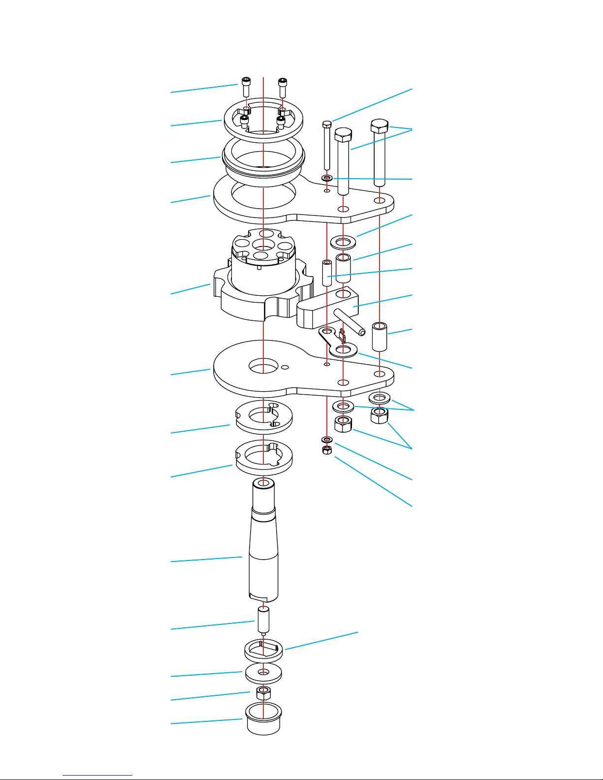
Spindle cap
Exploded view of spindle components
Upper bearing
Lower bearing
Spindle cap screws (4x)
Upper drive link
Drive hub
Lower drive link
Spindle
Encoder stud Spindle retainers
Note: Multiple retainers of varying
thicknesses are usually installed to
achieve a clearance of .015”-.030”
between the washer and the spindle.
is allows the spindle to freely rotate
but minimizes up and down play.
Spindle retainer washer
3/4”-10 hex nut
Upper drive link spacer
(3/8” thick)
Lower drive link spacer
(1/2” thick)
3/4”-10 hex nuts (2x)
3/8”-16 hex nut
3/8” washer
3/4” washers (2x)
3/4”-16 x 3.75“ long hex bolts (2x)
NOTE: Does NOT use washers
3/8”-16 x 3.5“ long hex bolt
Drive pawl spring bracket
Drive pawl
3/8” washer
Pin spacer (1.02” i.d.)
Drive link sleeve (1” o.d.)
Drive link sleeve (5/8” o.d.)
Drive link sleeve (1” o.d.)
Page 15

Installing the Encoder
1) Install the encoder mount.
2) Install the encoder onto the encoder bracket
and tighten. Do not place it into the machine.
3) Slide the encoder into the coupling
approximately .225” and tighten. Be careful not
to strip the small bolt.
NOTE: The shaft must not protrude into the
slotted section of the coupler or it will not be
able to ex properly.
4) Position this assembly into the bender as
shown. Do not tighten the 1/4” bolts. Adjust the
encoder threaded rod up or down so that when
tighten, the encoder’s shaft only extends into it
approximately .225” also.
5) Securely tighten the encoder stud’s 3/4” nut.
6) Tighten the 1/4” bracket bolts being careful not
to force the coupler out of alignment.
7) Tighten the coupler’s upper socket head bolt.
8) Rotate the spindle by hand and verify coupler
does not show signs of excessive misalignment.
Max run out is .020” total over 360o.
1/4” hex nuts 1/4” washers
1/4”-20 x 3/4” bolt
& 1/4” washers
Absolute position encoder
(Installed with a thin nut that is
not shown)
Encoder
coupling
Encoder bracket
3/8” x 1”
bolts (3x)
3/8” hex nuts
(3x)
Encoder guard
Encoder mount
Encoder stud
3/4” hex nut
Encoder components
Page 16
Bending Tutorial Using Template Bends
The Easy Way To Position Bends
Learning to operate the bender is fairly easy. The real challenge is accurately placing the tube into the bender
so that the bend comes out in the right position. This tutorial will teach you a technique called ‘Template Bending’
to make a rollbar. This is a good example because it’s a common request and there are no simple 90obends.
First, you need to make a template. A template is a piece of tubing bent to 90owith 6” or more of straight
tubing left on each side of the bend. A reference line cut into the template that allows you to visualize where the
bendmarks should be placed on the tube to be bent. After bending your tube will spring out to a larger radius
than the forming die’s size indicates. The larger the O.D. or the stronger the tube, the greater the springback.
For instance, chromemoly tubing will springback roughly twice as far as the exact same size and wall thickness
of welded seam mild steel tubing. By using a template bend of the same kind of tubing you are going to bend,
you do not have to worry about this springback be cause the template has already sprung out to its nished size.
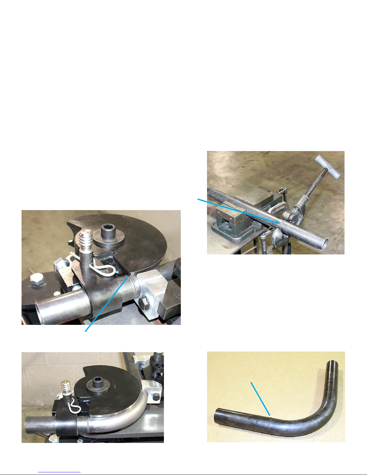
Cut a piece of tubing roughly 30” long. Next, cut an accurate
line all the way around the tube 6” from the end. The best
way to do this is to use a pipe cutter. Hand scribing this line
is dif cult and not rec ommended. To the right is shown the
reference line being cut into the tube.
Cut reference line
Load the tube into the bender as shown to the
lower left. The reference line must be positioned
EXACTLY at the at side of the forming die where
the u-strap block has been welding onto the die.
You must always use the forming die’s at side as
a reference. Bend the tube to 90o. If the forming
die has a lock bolt on it, use it to securely tighten
the tubing in place. It’s very important that this
mark stays in line with the die’s at edge during the
bending process or the template will not give you
accurate results later.
Reference line installed at the at side of the forming die
e completed template
Reference line
Page 17

The rollbar will be 40” tall from the oor to its UPPER
side. It will be 62” wide, outside to outside. The top two
bends are 70oand the two lower bends are 20o.
To determine the total length of tubing needed,
you could sit down and calculate it. Time usually cost
more than tubing, so let’s do it the easy way. Take the
total width of the rollbar (62”) and add it to twice the
height (40”). This gives us a length of 142” (62” + 40”
+ 40”). This is slightly longer than we actually need,
but there’s a popular rule in fabricating: It is easier to
remove material then to add it. Through experience
you will learn how much extra tubing you must leave
to complete the part.
An important rule of bending is, if possible, always
make the bends closest to the center rst and work
your way out. This allows you to make measurement
corrections between bends. Based on this rule, place a mark at the center of the rollbar tube. This is shown
below.
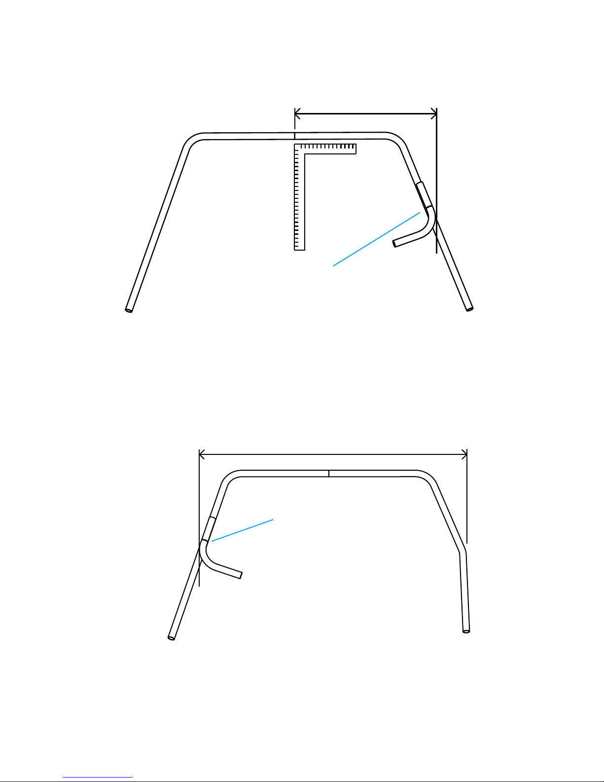
BEND 1:
The rst bend will be the upper right side bend. The upper dimension of the rollbar is 50”. From the center of
the rollbar to the outside of the bend is 25” (50” divided by 2). Lay the tube to be bent on the oor and hold the
template above and parallel to it as shown below. The scribed side of the template will always face towards the
center of the tube being bent. Using a tape measure, slide the template left or right until it is 25” from its outside
edge to the rollbar’s center mark as shown to the right. Using a marker, draw a line on the rollbar directly below the
scribed line. Since the desired bend is only 70oand the template is 90o, you will have to use your best judgement
of when the template is 25” out. This gets easier with experience. Take note of what side of this mark the bend
needs to be and draw an ‘X’ there so that when you load the tube into the bender you’ll be bending on the correct
side. Now, load the tube into the bender and make
the rst bend. Don’t forget to over bend a little to
account for tube springback. For this material 3 to
4 degrees should be sufcient. Once you know the
correct over bend required, you may want to record
it for future reference.
BEND 2:
Place the template above the rollbar tube with the
reference line facing bend 1 as shown below. Slide it to the desired 50” outside to outside of the two top rollbar
bends. Do NOT use the tube’s center mark as a reference and place the template 25” left of center. The reason
is that if the rst bend was not made at the correct position to achieve 25” from rollbar’s center you can correct
this error in the second bend’s position. Mark the rollbar tube exactly underneath the template line and make the
second 70obend.
Erase the center mark on the rollbar tube and mark a
new center exactly midway between the outside of the
two bends. Why? Let’s say your measurement shows
the two top bends are really 50 1/4” wide instead of the
desired 50”. In that case, your old center mark could
be off by as much as a 1/4”. The NEW center mark
corrects this error. With template bending your errors
can generally be xed in the next bend. If you had
started bend 2 from the rollbar’s center mark you would
not have made the correction. Eventually, every bend
adds a little more error and you end up with a rollbar
that does not t.
62"
40"
20°
70°
50"
Rollbar dimensions
25”
Template positioned for the 1st bend.
Tube’s center mark
50”
Do NOT use this
mark as a reference
for bend 2
Template’s reference line
Template positioned for the 2nd bend.
Page 18
BEND 3:
At this step you may want to use a large 90osquare to help position the template. Position the template above
the rollbar tube with the template line facing up towards the top of the rollbar as shown in to the right. Slide the
template up or down the rollbar tube until its outside is 31” from the rollbar’s center. Mark your tube and make
the bend.
BEND 4:
Position the template with the template line facing up towards the top of the rollbar as shown to the right. Slide
the template up or down the rollbar tube until its outside is 62” from the outside of the 3rd bend. Also, verify the
bend is the same distance down the tube from the top of the rollbar. If all is correct mark the tube and make the
bend.
Lastly, cut the ends of the tube to make the rollbar 40” tall and your done.
31”
Template positioned for the 3rd bend.
62”
Template positioned for the 4th and last bend.
Template’s reference line
Template’s reference line
Page 19
Table of contents
Popular Lathe manuals by other brands


Mac Afric
Mac Afric BL200L Operation manual

tornos
tornos MultiDeco Series Equipment Logbook Assembly, operation and maintenance

LNS
LNS TRYTON 112 Startup manual

Baileigh
Baileigh PL-1340E-1.0 Operator's manual

CabKing
CabKing 8V1 instruction manual

Intelitek
Intelitek spectraLIGHT 0400 Quick Start Install Guide


