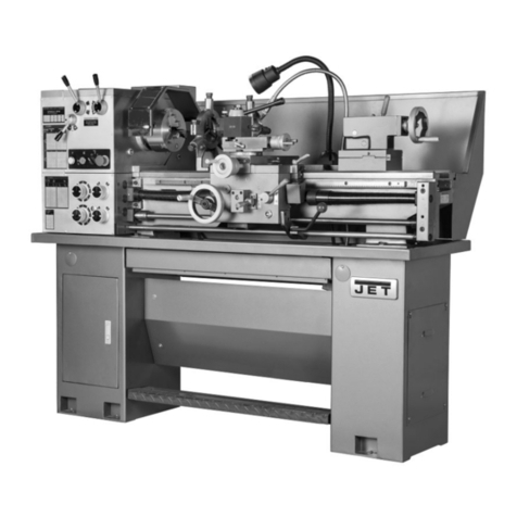
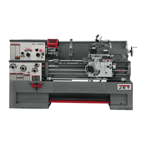
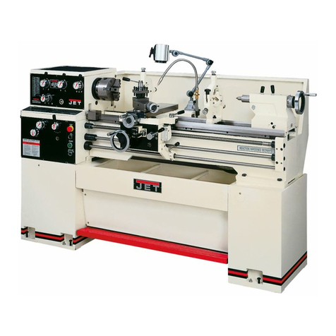
Jet BD-11G User manual

CE-Conformity Declaration
CE-Konformitätserklärung
Déclaration de Conformité CE
Product / Produkt / Produit:
Metal Lathe
Die Metall - Dreher
Tour de métal
BD-11G
Brand / Marke / Marque:
JET
Manufacturer / Hersteller / Fabricant:
JPW (Tool) AG, Tämperlistrasse 5, CH-8117 Fällanden
Schweiz / Suisse / Switzerland
We hereby declare that this product complies with the regulations
Wir erklären hiermit, dass dieses Produkt der folgenden Richtlinie entspricht Par la
présente, nous déclarons que ce produit correspond aux directives suivantes
2006/42/EC
Machinery Directive
Maschinenrichtlnie
Directive Machines
2006/95/EC
electromagnetic compatibility
elektromagnetische Verträglichkeit
compatibilitéélectromagnétique
Directive Basse Tension
designed in consideration of the standards
und entsprechend folgender zusätzlicher Normen entwickelt wurde
et étédéveloppédans le respect des normes complémentaires suivantes
EN ISO 12100:201 0; EN 60204-1 :2006+A 1 :2009+AC:2010
EN 61000-6-2:2005; EN 61000-6-4:2007+A1:2011
Responsible for the Documentation / Dokumentations-Verantwortung / Résponsabilitéde Documentation:
Hansjörg Meier
Head Product-Mgmt. / Leiter Produkt-Mgmt. / Resp. Gestion des
Produits JPW (Tool) AG
2016-10-10 Alain Schmid, General Manager
JPW (Tool) AG, Tämperlistrasse 5, CH-8117 Fällanden
Schweiz / Suisse / Switzerland
2

In addition to the safety requirements contained in these
operating instructions and your country’s applicable
regulations, you should observe the generally recognized
technical rules concerning the operation of metal machines.
Any other use exceeds authorization.
In the event of unauthorized use of the machine, the
manufacturer renounces all liability and the responsibility is
transferred exclusively to the operator.
General safety notes
Read and understand the entire instruction manual
before attempting assembly or operation.
Keep this operating instruction close by the machine,
protected from dirt and humidity, and pass it over to the
new owner if you part with the tool.
No changes to the machine may be made.
Daily inspect the function and existence of the safety
appliances before you start the machine.
Do not attempt operation in this case, protect the machine by
unplugging the power cord.
Before operating the machine, remove tie, rings, watches,
other jewellery, and roll up sleeves above the elbows.
Remove all loose clothing and confine long hair.
Wear safety shoes; never wear leisure shoes or sandals.
Always wear the approved working outfit:
- safety goggles
- ear protection
Do not wear gloves while operating this machine.
Install the machine so that there is sufficient space for safe
operation and workpiece handling.
Keep work area well lighted.
The machine is designed to operate in closed rooms and
must be bolted stable on firm and levelled table surface or
on the supplied cabinet stand.
Make sure that the power cord does not impede work and
cause people to trip.
Keep the floor around the machine clean and free of
scrap material, oil and grease.
Stay alert!
Give your work undivided attention.
Use common sense. Do not operate the machine when you
are tired.
Keep an ergonomic body position.
Maintain a balanced stance at all times.
Do not operate the machine under the influence of drugs,
alcohol or any medication. Be aware that medication can
change your behaviour.
Never reach into the machine while it is operating or running
down.
Keep children and visitors a safe distance from the work area.
Never leave a running machine unattended. Before you leave
the workplace switch off the machine.
Do not operate the electric tool near inflammable liquids or
gases.
Observe the fire fighting and fire alert options, for example the
fire extinguisher operation and place.
Do not use the machine in a dump environment and do
not expose it to rain.
Before machining, remove any nails and other foreign bodies
from the workpiece.
Work only with well sharpened tools.
Machine only stock which rests securely on the table.
Always close the chuck cover before you start the machine.
Specifications regarding the maximum or minimum size of the
workpiece must be observed.
Do not remove chips and workpiece parts until the machine
is at a standstill.
Do not stand on the machine.
Connection and repair work on the electrical installation
may be carried out by a qualified electrician only.
Have a damaged or worn power cord replaced immediately.
Make all machine adjustments or maintenance with
the machine unplugged from the power source.
Do not over extrude material from the back of spindle
bore while machine running.

3
Table of contents
1. Safety
1.1 Safety warnings (warning notes
) ………………………………………………………………………………
6
1.1.1 Classification of hazards
……………………………………………………………………………......
6
1.1.2 Other pictograms
…………………………………………………………………………………………
7
1.2 Proper
use
……………………………………………………………………………………………………….
8
1.3 Possible dangers caused by the machine…………………………………………………………………..8
1.4 Qualification of personnel
………………………………………………………………………………….......
9
1.4.1 Target group……………………………………………………………………………………………..9
1.4.2 Authorised personnel………………………………………………………………………………….10
1.4.3 Obligations of the operator……………………………………………………………………….......10
1.4.4 Obligations of the user
…………………………………………………………………………...........
10
1.4.5 Additional qualification requirements………………………………………………………………..10
1.5 User positions
……………………………………………………………………………………………….......
10
1.6 Safety devices
………………………………………………………………………………………………......
10
1.6.1 EMERGENCY STOP button
……………………………………………………………………………
11
1.6.2 Protective cover………………………………………………………………………………………… 11
1.6.3 Lathe chuck key
………………………………………………………………………………………….
11
1.6.4 Prohibition, warning and mandatory labels
…………………………………………………………...
12
1.7 Safety check
…………………………………………………………………………………………………….
12
1.8 Individual protection gear
……………………………………………………………………………………....
12
1.9 Safety during operation
……………………………………………………………………………………......
13
1.10 Safety during maintenance
…………………………………………………………………………………….
13
1.10.1 Disconnecting the lathe and making it safe…………………………………………………………13
1.10.2 Using lifting equipment………………………………………………………………………………..14
1.10.3 Mechanical maintenance work
……………………………………………………………….............
14
1.11 Accident report
………………………………………………………………………………………………….
14
1.12 Electrical system
………………………………………………………………………………………………..
14
2. Technical data
Power connection
………………………………………………………………………………………………….
15
Machine data
……………………………………………………………………………………………………….
15
Dimensions
…………………………………………………………………………………………………………
15
Work area
…………………………………………………………………………………………………….........
15
Environmental conditions
…………………………………………………………………………………………
15
Operating material
…………………………………………………………………………………………………
15
2.1 Emissions
………………………………………………………………………………………………………
16
3Assembly
3.1 Extent of
supply………………………………………………………………………………………….........
16
3.2 Transport
……………………………………………………………………………………………………….
16
3.3 Storage
…………………………………………………………………………………………………….......
16
3.4 Installation and assembly
…………………………………………………………………………………….
17
3.4.1 Requirements of the installation site
…………………………………………………………….......
17
3.4.2 Load suspension point
……………………………………………………………………………...…
17
3.4.3 Installation
……………………………………………………………………………………………....
17
3.4.4 Installation drawing
…………………………………....................................................................
18
3.5 First
use……………………………………………………………………………………………………......
18
3.5.1 Cleaning and greasing
………………………………………………………………………………...
19
3.2.2 Visual inspection……………………………………………………………………………………...19
4
3.5.3 Run test………………………………………………………………………………………………..19
3.5.4 Power connection………………………………………………………………………………….....19
3.5.5 Functional test…………………………………………………………………………………………20
3.6 Change gears…………………………………………………………………………………………………20
3.6.1 Assembly of gears changing…………………………………………………………………….......20
3.6.2 Table of the gear wheels…………………………………………………………………………......21
4. Design and function
4.1 Construction features
……………………………………………………………………………………….....
21
4.2 Lathe bed
………………………………………………………………………………………………............
22
4.3 Headstock
……………………………………………………………………………………………………....
22
4.4 Feed gear
……………………………………………………………………………………………………….
22
4.5 Apron
…………………………………………………………………………………………………………....
22
4.6 Tailstock
…………………………………………………………………………………………………..........
22
5. Operation
5.1 Safety
……………………………………………………………………………………………………………
22
5.2 Control and indicating elements
……………………………………………………………………………...
22
5.2.1 BD-11…………………………………………………………………………………………………..23
5.3 Control elements
……………………………………………………………………………………………....
23
5.4 Toolholder
………………………………………………………………………………………………………
23
5.4.1 Tool height
……………………………………………………………………………………………...
24
5.4.2 Tool angle
………………………………………………………………………………………………
24
5.5 Lathe chuck
………………………………………………………………………………………………........
24
5.5.1 Head spindle seat
……………………………………………………………………………………...
24
5.6 Adjusting the speed
……………………………………………………………………………………………
24
5.6.1 Protective cover of the headstock
……………………………………………………………………
24
5.6.2 Changing the speed
range……………………………………………………………………………
25
5.6.3 Speed table
……………………………………………………………………………………………
25
5.7 Adjusting the feed
……………………………………………………………………………………………..
25
5.7.1 Selector
switch…………………………………………………………………………………………
25
5.7.2 Changing the change gears…………………………………………………………………………25
5.7.3 Engaging lever
………………………………………………………………………………………....
26
5.8 Lathe saddle with cross and top slide
……………………………………………………………………...
26
5.8.1 Immobilizing the lathe saddle……………………………………………………………………….26
5.8.2 Turning tapers with the top slide……………………………………………………………………26
5.8.3 Cross-adjustment of the tailstock
……………………………………………………………….......
26
5.9 Tailstock sleeve
………………………………………………………………………………………………..
26
5.10 Clamping a workpiece into the lathe chuck
……………………………………………………………….
26
5.10.1 Replacing the clamping jaws on the lathe chuck
………………………………………………....
27
5.11 General working notes
……………………………………………………………………………………….
27
5.11.1 Fitting a follow rest
……………………………………………………………………………………
27
5.11.2 Coolant
…………………………………………………………………………………………………
27
6. Maintenance
6.1 Safety
…………………………………………………………………………………………………………...
28
6.1.1 Preparation
………………………………………………………………………………………….....
28
6.1.2 Restarting……………………………………………………………………………………………..29
6.2 Inspection and maintenance
…………………………………………………………………………….......
29
6.3 Repair
…………………………………………………………………………………………………………..
30
6.4 Exploded view of top slide
…………………………………………………………………………………...
31

5
6.4.1 Spare parts list of top slide
…………………………………………………………………………..
32
6.5 Exploded view of cross slide
………………………………………………………………………………..
33
6.5.1 Spare parts list of cross slide
………………………………………………………………………..
34
6.6 Exploded view of apron
………………………………………………………………………………………
35
6.6.1 Spare parts list of apron
……………………………………………………………………………...
36
6.7 Exploded view of lathe bed
…………………………………………………………………………………..
37
6.7.1 Spare parts list of lathe bed
………………………………………………………………………….
38
6.8 Exploded view of feed gear
………………………………………………………………………………….
39
6.8.1 Spare parts list of feed gear
…………………………………………………………………………
40
6.9 Exploded view of headstock
………………………………………………………………………………...
41
6.9.1 Spare parts list of headstock
………………………………………………………………………..
42
6.10 Exploded view of change gear
……………………………………………………………………………..
43
6.10.1 Spare parts list of change gear
…………………………………………………………………….
44
6.11 Wiring diagram
……………………………………………………………………..………………………
46
6.12 Standard Accessories List………………………………………………………………………….….…. 48

6
GB - ENGLISH
Operating Instructions
Dear Customer,
Many thanks for the confidence you have shown in us with the purchase of your new JET-machine. This manual has been
prepared for the owner and operators of a JET BD-11 Operating Manual Lathe to promote safety during installation,
operation and maintenance procedures. Please read and understand the information contained in these operating instructions
and the accompanying documents. To obtain maximum life and efficiency from your machine, and to use the machine safely,
read this manual thoroughly and follow instructions carefully.
Warranty
The Seller guarantees that the supplied product is free from material defects and manufacturing faults. This warranty does not
cover any defects which are caused, either directly or indirectly, by incorrect use, carelessness, accidental damage, repair,
inadequate maintenance or cleaning and normal wear and tear.
Guarantee and/or warranty claims must be made within twelve months from the date of purchase (date of invoice). Any further
claims shall be excluded.
This warranty includes all guarantee obligations of the Seller and replaces all previous declarations and agreements
concerning warranties.
The warranty period is valid for eight hours of daily use. If this is exceeded, the warranty period shall be reduced in proportion
to the excess use, but to no less than three months.
Returning rejected goods requires the prior express consent of the Seller and is at the Buyer’s risk and expense.
Further warranty details can be found in the General Terms and Conditions (GTC). The GTC can be viewed at
www.jettools.com or can be sent by post upon request.
The Seller reserves the right to make changes to the product and accessories at any time.
1. Safety
This part of the operating manual
• explains the meaning and use of the warning references contained in the operating manual,
• explains how to use the lathe properly,
• highlights the dangers that might arise for you or others if these instructions are not obeyed,
• tells you how to avoid dangers.
In addition to this operating manual please observe
• applicable laws and regulations,
• legal regulations for accident prevention,
• the prohibition, warning and mandatory signs as well as the warning notes on the lathe.
European standards must be observed during installation, operation, maintenance and repair of the lathe.
If European standards are not applied in the national legislation of the country of destination, the specific
applicable regulations of each country must be observed.
Where necessary, the required measures must be taken to comply with the specific regulation of each country
before the lathe is first used.

7
ALWAYS KEEP THIS DOCUMENT CLOSE TO THE LATHE FOR FUTURE REFERENCE.
1.1 Safety warnings (warning notes)
1.1.1 Classification of hazards
We classify the safety warnings into various levels. The table below gives an overview of the classification of
symbols (pictograms) and warnings for the specific danger and its (possible) consequences.
Pict
ogra
m
Alarm
expression
Definition/Consequences
DANGER!
Imminent danger that will cause serious injury or death
to
personnel.
WARNIN
G!
Risk: A danger that might cause serious injury or death
to
personnel.
CAUTION!
Danger or unsafe procedure that might cause injury to
personnel or damage to property.
ATTE
NTION!
Situation that could cause damage to the machine and
product and other types of damage.
No risk of injury to personnel.
INFORMATI
ON
Application tips and other important or useful inform
ation
and notes.
No dangerous or harmful consequences for personnel
or
objects.
In the case of specific dangers, we replace the pictogram
or
General danger with a warning of injuries to hands, hazardous electrical volt- age, rotating parts.
1.1.2 Other Pictograms
Warning of automatic start-
up
Act
ivation forbid
den
P
ull the
mains plug
Use protective goggl
es
Use ear
protection
Use protective gloves
Use
protective boots
Wear a safety
suit
Protect
the en
vironment
Contact ad
dress

8
1.2 Proper Use
WARNING!
Improper use of the lathe
Ь will endanger personnel,
Ь will endanger the machine and other material property of the operator,
Ь may affect proper operation of the machine.
The machine is designed and manufactured to be used in environments where there is no potential
danger of explosion.
The lathe is designed and manufactured for straight turning and facing round or regularly formed three-,
six- or twelve-square workpieces in cold metal, castings and plastics or similar materials that do not
constitute a health hazard or do not create dust, such as wood, Teflon®, etc. The lathe must only be
installed and operated in a dry and well-ventilated place. The workpieces may only be clamped in the
lathe chuck using the special check-key provided.
If the lathe is used in any way other than as described above, modified without the authorisation of JPW
Machine or operated with different process data, then it is being used improperly.
We do not take liability for damage caused by improper use.
We would like to stress that any modifications to the construction, or technical or technological
modifications that have not been authorised by JPW Machine will also render the guarantee null and
void.
It is also part of proper use that
Ь the maximum values for the lathe are complied with,
Ь the operating manual is observed,
Ь inspection and maintenance instructions are observed.
In order to achieve cutting performance, it is essential to choose the right turning tool, feed, tool
pressure, cutting speed and coolant.
WARNING!
Very serious injury due to improper use.
It is forbidden to make any modifications or alterations to the operating values of the machine. These
could endanger personnel and cause damage to the machine.
1.3 Possible dangers caused by the machine
The lathe has undergone a safety inspection (analysis of danger with assessment of risks). It has been
designed and built on the basis of this analysis using the latest technological advances.
Nonetheless, there remains a residual risk, since the machine operates with
Ь high revolutions,
Ь rotating parts,
Ь electrical voltage and currents.
We have used construction resources and safety techniques to minimise the health risk to per- sonnel
resulting from these hazards.

9
If the lathe is used and maintained by personnel who are not duly qualified, there may be a risk
resulting from incorrect operation or unsuitable maintenance.
INFORMATION
All personnel involved in assembly, commissioning, operation and maintenance must
Ь be duly qualified,
Ь follow this operating manual.
Disconnect the machine whenever cleaning or maintenance work is being carried out.
WARNING!
THE LATHE MAY ONLY BE USED WITH THE SAFETY DEVICES ACTIVATED.
Disconnect the lathe whenever you detect a failure in the safety devices or when they are
not fitted!
All additional installations carried out by the operator must incorporate the prescribed safety devices.
As the machine operator, this will be your responsibility!
“Safety devices“ on page 11
1.4 Qualification of personnel
1.4.1 Target group
This manual is addressed to
Ь operators,
Ь users,
Ь maintenance stuff.
The warning notes therefore refer to both operation and maintenance of the machine.
Determine clearly and unequivocally who will be responsible for the different activities on the
machine (use, maintenance and repair).
Vague or unclear assignment of responsibilities constitutes a safety hazard!
Always disconnect the machine plug from the mains. This will prevent it being used by
unauthor- ised personnel.
INFORMATION
All personnel involved in assembly, commissioning, operation and maintenance must
Be duly qualified
follow this operating manual.

10
In the event of improper use
Ь there may be a risk to personnel,
Ь there may be a risk to the machine and other material property,
Ь correct functioning of the lathe may be affected.
1.4.2 Authorised personnel
WARNING!
Incorrect use and maintenance of the machine constitutes a danger for personnel, objects and
the environment.
Only authorised personnel may operate the machine!
The only personnel authorised to use this machine and perform maintenance on it are trained and
instructed technical staff working for the operator and manufacturer.
1.4.3 Obligations of the operator
The operator must instruct staff at least once a year on
Ьall safety standards that apply to the machine,
Ьoperation,
Ьaccredited technical guidelines. The operator must also
Ьcheck staff's understanding,
Ьdocument training/instruction,
Ьrequire staff to confirm participation in training/instruction by means of a signature,
Ьcheck whether the staff are aware of safety and of dangers in the workplace and whether they
observe the operating manual.
1.4.4 Obligations of the user
The user must
Ьhave read and understood the operating manual,
Ьbe familiar with all safety devices and regulations,
Ьbe able to manipulate the machine.
1.4.5 Additional qualification requirements
For work on electrical components or equipment there are additional requirements:
ЬThis work must only be carried out by a qualified electrician or person working under the instructions
and supervision of a qualified electrician.
Before carrying out work on electric components or operating units the following measures must be
taken, in the order given.
Disconnect all poles
Ensure that the machine cannot be turned on again
Check that there is no voltage
1.5 User positions
The user must stand in front of the machine.
1.6 Safety devices
Use the lathe only with properly functioning safety devices.

Stop the lathe immediately if there is a failure in the safety device or if it is not functioning for any
reason.
It is your responsibility!
If a safety device has been activated or has failed, the lathe must only be used when
Ь the cause of the failure has been removed,
Ь it has been verified that there is no resulting danger for personnel or objects.
WARNING!
If you bypass, remove or override a safety device in any other way, you are endangering
yourself and other personnel working with the machine. The possible consequences are
Ь damage as a result of components or parts of components flying off at high speed,
Ь contact with rotating parts,
Ь fatal electrocution.
The lathe includes the following safety devices:
Ь Self-latching, lockable EMERGENCY STOP button
Ь Screwed-down protective cover on the headstock
Ь Special key for the lathe chuck
1.6.1 EMERGENCY STOP button
1.6.2 Protective cover
The headstock of the lathe is fitted with a screwed-down protective cover.
WARNING!
Remove the protective cover only after the mains plug of the lathe has been pulled.
1.6.3 Lathe chuck key
The lathe is equipped with a special key for chucks. Once the lathe chuck key has been released, it is pushed out
of the lathe chuck by a spring.
11

12
CAUTION!
Only operate the lathe using this key.
1.6.4 Prohibition, warning and mandatory labels
INFORMATION
All warning labels must be legible. Check them regularly.
1.7 Safety check
Check the lathe at least once per shift. Inform the person responsible immediately of any dam- age,
defect or change in operating function.
Check all safety devices
Ьat the beginning of each shift (with the machine stopped)
Ьonce a week (with the machine in operation)
Ьafter every maintenance and repair operation
Check that prohibition, warning and information labels and the markings on the lathe
Ьcan be identified (if not, clean them)
Ьare complete
INFORMATION
Use the following table for organizing the checks.
General check
Equipment Check
OK
Protective
cover,
Fitted, firmly bolted and not damaged
Labels, markings Installed and legible
Date: Checked by (signature):
Run test
Equipment Check
OK
EMERGENCY ST
OP
button
When the EMERGENCY STOP button is activated, the
lathe should be switched off.
Lathe chuck key Once the chuck key has been released, it should be
automati- cally pressed out of the lathe chuck.
Date: Checked by (signature):
1.8 Individual protection gear

13
For certain work individual protection gear is required.
Protect your face and eyes: During all work, and specifically work during which your face and eyes are
exposed to hazards, a safety helmet with a face guard should be worn.
Use protective gloves when lifting or handling pieces with sharp edges. Wear safety shoes when
fitting, dismantling or transporting heavy components.
Use ear protection if the noise level (immission) in the workplace exceeds 80 dB(A).
Before starting work, make sure that the prescribed individual protection gear is available in the
workplace.
CAUTION!
Dirty or contaminated body protection gear can cause disease. Clean it after every use and
once a week.
1.9 Safety during operation
In the description of work with and on the machine we highlight the dangers specific to that work.
WARNING!
Before activating the lathe, double check that this will not endanger other people and cause
damage to equipment.
Avoid unsafe working practises:
ЬMake sure your work does not endanger anyone.
ЬClamp the workpiece tightly before activating the lathe.
ЬFor clamping workpieces, only use the special chuck key supplied.
ЬMind the maximum chuck opening.
ЬUse protective goggles.
ЬDo not remove turning chips by hand. To remove turning chips, use a chip hook and/or hand brush.
ЬClamp the turning tool at the correct height and with the least possible overhang.
ЬTurn off the lathe before measuring the workpiece.
ЬThe instructions in this manual must be observed during assembly, handling, maintenance and repair.
ЬDo not work on the lathe if your concentration is reduced, for example, because you are tak- ing
medication.
ЬObserve the rules for preventing accidents issued by your association for the prevention of
occupational accidents and safety in the workplace or other inspection authorities.
ЬInform the inspector of any danger or failure.
ЬStay at the lathe until all rotating parts have come to a halt.
ЬUse prescribed protection gear. Make sure to wear a well-fitting work suit and, where neces- sary, a
hairnet.
1.10 Safety during maintenance
Inform operating staff in good time of any repair and maintenance work.
Report all safety-relevant changes or performance details of the lathe. Document all changes, have the
operating manual changed accordingly and train the machine operators.
1.10.1 Disconnecting the lathe and making it safe
Pull the mains plug before beginning any maintenance or repair work. All machine components and
hazardous voltages and movements must have been disconnected.

Place a warning sign on the machine.
WARNING!
Before reconnecting the machine, make sure that the change-
over switch on the lathe is in the "o" position
1.10.2 Using lifting equipment
WARNING!
Use of unstable lifting and suspension gear that might break under load can cause very
serious injuries or even death.
Check that the lifting and load suspension gear is of sufficient load capacity and in per- fect condition.
Observe the rules for preventing accidents issued by your association for the prevention of
occupational accidents and safety in the workplace or other inspection authorities.
Hold the loads properly.
Never walk under suspended loads!
1.10.3 Mechanical maintenance work
Remove all protection and safety devices before beginning maintenance work and re-install them once
the work has been completed. These include:
Ь Covers
Ь Safety indications and warning signs
Ь Earth (ground) connection
If you remove protection or safety devices, refit them immediately after completing the work. Check that
they are working properly!
1.11 Accident report
Inform your superiors and JPW (Tool) AG immediately in the event of accidents, possible sources of
danger and any actions which almost led to an accident (near misses).
These near misses can have many possible causes.
The sooner they are notified, the faster the causes can be eliminated.
1.12 Electrical system
Have the machine and/or the electric equipment checked regularly, and at least every six months.
Eliminate immediately all defects such as loose connections, defective wires etc.
A second person must be present during work on live components, to disconnect the power in the
event of an emergency. Disconnect the lathe immediately if there are any anomalies in the power
supply!
14

2. Specifications
Model number.................................................................................................................................................................................... BD-11G
Stock number……………………………………………………………………....................................................................................................... 50000915M
Motor and electricals:
Motor type…………………………………………………….................................................................................................................Induction motor
Motor power....................................................................................................................................................................................1.1 kW
Power supply.......................................................................................................................................................................230V, PE, 50Hz
Protection class.................................................................................................................................................................................... IP
Machine lamp.......................................................................................................................................................Halogen lamp 24V, 35W
Coolant pump...................................................................................................................................................................................... 40W
Capacities:
Centre height.................................................................................................................................................................................. 140mm
Swing over bed...............................................................................................................................................................................280 mm
Swing over cross slide.................................................................................................................................................................... 170 mm
Distance between Centres.............................................................................................................................................................700 mm
Spindle:
Spindle nose mounting..................................................................................... A125 - DIN 6350 (Ø125mm, Ø96mm, Ø108-3xØ9/4xØ9)
Spindle bore..................................................................................................................................................................................... 26 mm
Spindle taper........................................................................................................................................................................................MT4
Number of spindle speeds........................................................................................................................................................................ 6
Range of spindle speeds................................................................................................................................................... 150 ~ 2000 /min
Tailstock:
Tailstock ram travel..........................................................................................................................................................................85 mm
Tailstock taper......................................................................................................................................................................................MT2
Tool Slide:
Cross slide travel............................................................................................................................................................................ 145 mm
Top slide travel.................................................................................................................................................................................60 mm
Tool size max...............................................................................................................................................................................12x12mm
Lead screw pitch................................................................................................................................................................................ 3 mm
Longitudinal feeds.........................................................................................................(6x) 0.07 / 0,1 / 0,14 / 0.2 / 0.28 / 0.40 mm/rev
Metric threads........................................................................................................................................................(21x) 0.2~4.0 mm/rev
Inch threads.......................................................................................................................................................................(21x) 8 ~ 56 TPI
Materials:
Machine Bed............................................................................................................ Cast iron, induction hardened and precision ground
Headstock, tailstock, slides........................................................................................................................................................... Cast iron
Spindle bearings..............................................................................................................................Taper roller bearings, quality level P5
Sound emission in idle 1........................................................................................................................................................ 73.4 dB (LpA)
Sound emission during cutting 1............................................................................................................................................78.3 dB (LpA)
1Sound emission measured according to EN ISO 11202, in 1m distance, 1.6m above ground. The specified values are emission levels
and are not necessarily to be seen as safe operating levels. As workplace conditions vary, this information is intended to allow the user
to make a better estimation of the hazards and risks involved only.
Dimensions and Weights:
Overall dimensions, assembled (W x D x H)........................................................................................................... 1380 x 700 x 1285 mm
Shipping dimensions (W x D x H) (Seperate packing)............................................................. 1320 X700 X 690mm + 820X680X430mm
Shipping dimensions (W x D x H) (Whole packing)................................................................................................ 1400 X 700 X 1470mm
Net weight (approximate)................................................................................................................................................................ 240 kg
Shipping weight (approximate)........................................................................................................................................................ 270 kg
L = length; W = width; H= height; D= depth
The specifications in this manual were current at time of publication, but because of our policy of continuous improvement, JET reserves
the right to change specifications at any time and without prior notice, without incurring obligations.
15
54

16
Environmental conditions
BD-11G
Temperature
5 - 35 °C
Humidity
25 - 80 %
Operating material
BD-11G
Feed gear
Mobilgear 627 or equivalent oil
Bright steel parts and lubricating
il
Non-corrosive lubricating oil
Change gears
Chain oil (spray box)
2.1 Emissions
The level of noise emitted by the lathe is less than 70 dB(A).
INFORMATION
If the lathe is installed in an area where various machines are in operation, the acoustic influ-
ence (immission) on the operator of the lathe may exceed the legally permitted peak value in the
workplace.
We recommend the use of soundproofing and ear protection.
3. Assembly
INFORMATION
The lathe comes pre-assembled.
3.1 Extent of supply
When the machine is delivered, check immediately that the lathe has not been damaged during
shipping and that all components are included. Also check that no fastening screws have come loose.
Compare the parts supplied with the information on the packaging list.
3.2 Transport
WARNING!
Machine parts falling off forklift trucks or other transport vehicles could cause very seri- ous
or even fatal injuries. Follow the instructions and information on the transport case:
ЬCentres of gravity
ЬSuspension points
ЬWeights
ЬMeans of transport to be used
ЬPrescribed shipping position
WARNING!
Use of unstable lifting and load-suspension gear that might break under load can cause very serious
injuries or even death.
Check that the lifting and load suspension gear has sufficient load capacity and that it is in perfect
condition. Observe the rules for preventing accidents.
Hold the loads properly.
Never walk under suspended loads!

17
3.3 Storage
ATTENTION!
Improper storage may cause important parts to be damaged or destroyed.
Store packed or unpacked parts only under the intended environmental conditions.
Consult JPW (Tool) AG if the lathe and accessories have to be stored for a period of over
three months or under different environmental conditions to those given here.
3.4 Installation and assembly
3.4.1 Requirements of the installation site
Organize the work area around the lathe in accordance with local safety regulations.
Operation, maintenance and repair in the work area must not be hindered.
INFORMATION
The mains plug of the lathe must be freely accessible.
3.4.2 Load suspension point
ėFasten the load suspension gear around the lathe bed.
ė Make sure that you distribute the loads evenly so that the lathe cannot turn over while lifting.
ė Make sure that no add-on pieces or varnished parts are damaged due to the load suspension.
3.4.3 Installation
WARNING!
Danger of crushing and overturning. The lathe must be installed by at least 2 people.
ėCheck the horizontal orientation of the base of the lathe with a spirit level.
ėCheck that the foundation has sufficient floor-load capacity and rigidity.
ATTENTION!
Insufficient rigidity of the foundation leads to the superposition of vibrations between the machine and
the foundation (natural frequency of components). Insufficient rigidity of the entire lathe assembly also
rapidly causes the lathe to reach critical speeds, with unpleas- ant vibrations, leading to bad turning
results.
ė Position the lathe on the intended foundation.
ė Secure the lathe to the foundation or substructure of the machine using the (4) through holes.
If necessary, use anti-vibration elements (model S1) for your machine substructure.
INFORMATION
The installation site must be designed in accordance with ergonomic workplace requirements. The
installation drawings described below may differ from the real dimensions (cast parts). The
tolerances are in the range of the general tolerances according to DIN 7168 g.

18
3.4.4 Installation drawing BD-11
ATTENTION!
Tighten the fastening screws on the lathe only until it is firmly secured and cannot move during operation.
If the fastening screws are too tight and the foundation is uneven, the bed of the lathe may break.
3.5 First use
WARNING!
Personnel and equipment may be endangered if the lathe is first used by inexpert per- sonnel.
We do not take liability for damage caused by incorrect commissioning.

19
3.5.1 Cleaning and greasing
ė Remove the anticorrosive agent applied to the machine for transport and storage purposes.
We recommend the use of stove distillate.
ė Do not use any solvents, thinners or other cleaning agents which could corrode the varnish on the machine.
Follow the specifications and indications of the manufacturer of the cleaning agent.
ė Lubricate all bright machine parts with non-corrosive lubricating oil.
ė Grease the machine using the lubrication chart.
“Inspection and maintenance“ on page 44
3.5.2 Visual inspection
Check the oil level in the inspection glass of the feed gear.
( “Oil inspection glass of the feed gear“ on page 45)
3.5.3 Run test
ėCheck smooth running of all spindles.
INFORMATION
For manufacturing engineering reasons and for reasons of precision of fit, there may be occa- sional slight stiffness
in the spindles. This will disappear after a short time in use.
ėCheck the state of the lathe chuck and the turning jaws.
3.5.4 Power connection
Connect the following cables:
ė Connect the electric supply cable.
ė Check the fuse protection of your power supply against the technical data for the total con- nection value of the
lathe.
ATTENTION!
Please pay attention that all three phases (L1, L2, L3) are connected correctly. Most engine failure
result from incorrect connection, for instance the neutral
conductor ( N ) is being connected to a phase.
This might lead to the following results:
Ь The engine does get quickly very hot.
Ь The engine noise increases, i.e. becomes louder.
Ь The engine has no power.
When the phases are connected wrongly, the guarantee is being null and void.
ATTENTION!
Lathes with frequency converter must not be operated with a CEE plug. Connect the machine
permanently to a connection box (see EN 50178 / VDE 5.2.11.1)
Ь BD-11 lathe
INFORMATION
On lathes of the type "VARIO" the frequency converter (driving regulator) might release the FI protected switch of
your electrical supply. In order to avoid malfunction, you either need an FI protected switch sensitive for pulse
current or AC/DC sensitive.
In case of a mulfunction or release of the FI protected switch, please check the type installed. The following signs
indicate if you have one of the FI protected switches described above.
This manual suits for next models
1
Table of contents
Other Jet Lathe manuals

Jet
Jet JWL-1220VS User manual

Jet
Jet BD-920W Service manual

Jet
Jet JWL-1442VSK Service manual

Jet
Jet GH-2040 ZH User manual

Jet
Jet Revelation Reverb V2.0 User manual

Jet
Jet JWL-1840EVS Service manual

Jet
Jet JML-1014VS User manual

Jet
Jet CL-1640ZX User manual

Jet
Jet BDB-919 Service manual
Jet
Jet GH-1640ZX User manual