J.E. Adams 8670 Seies User manual

1
Models –8670 PROTEL DIGITAL SERIES
Page 2 Product Information
Page 3 Specifications
Page 4 Important Safety Instructions
Page 5 Product Dimensions
Page 6-9 Installation
Page 10 Timer Set-Up
Page 11 Operating Instructions & Maintenance
Page 11-12 Troubleshooting
Page 13-15 Protel Specific Troubleshooting
Page 16-17 Parts List
Page 18 Wiring Diagram
REV 3-23-22

2
PRODUCT INFORMATION
Please take a moment to fill out the information below in order to aid us with any future sales
or service inquiries. Model number and serial number information can be found on the
serial tag located inside the control box and/or on the lower exterior of the can. Key
number can be found on the tag that comes attached to the keys. There may be more than
one key number depending on unit.
Please keep this information with your records.
MODEL#:____________________________
SERIAL#:____________________________
KEY NUMBER(S):_____________________
DATE PURCHASED:___________________
DISTRIBUTOR:_______________________
J.E. Adams Industries
1025 63rd Ave. S.W.
Cedar Rapids, IA 52404
1-800-553-8861
www.jeadams.com
REV 3-23-22
3
Specifications
Unit specifications: 8670 “P” SERIES
Voltage: 120vac, 60hz
Amperage: (1) 15 amp service is required (twin cylinder compressors or compressor less)*
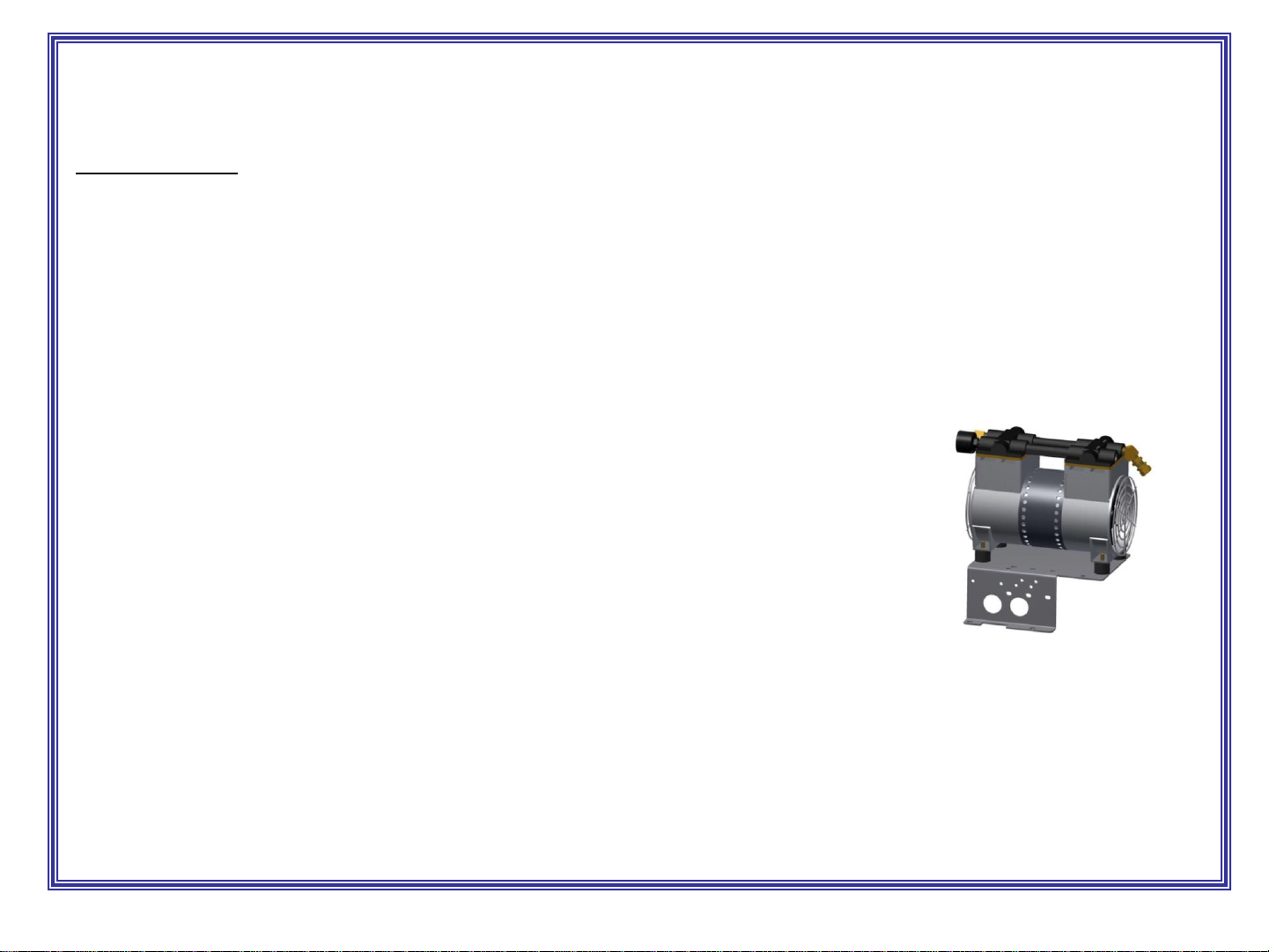
Compressors: ¾ hp, twin cylinder models
Water Solenoid: 120vac, 60hz
Timer: SSAC (standard –other available on request)
Weight: 77 lbs twin cylinder models, no packaging
DUTY CYCLE: 4 minutes on, 4 minutes off.
NOTE: “UNIT INTENDED FOR COMMECIAL USE ONLY”
Twin cylinder
REV 3-23-22
4
IMPORTANT SAFETY INSTRUCTIONS
When using an electrical appliance, basic precautions should always be followed, including the following:
READ ALL INSTRUCTIONS BEFORE USING (THIS APPLIANCE)
WARNING –To reduce the risk of fire, electric shock, or injury:
•Use only as described in manual. Use only manufactures recommended attachments.
•Do not allow to be used as a toy. Close attention is necessary when used by or near children.
•Do not put any object into openings. Do not use with any opening blocked; keep free of dirt and anything that may reduce
flow.
•Keep hair, loose clothing, fingers, and all parts of body away from openings and moving parts.
•Do not use near flammable or combustible liquids, such as gasoline, or use in areas where they may be present.
•Do not use near anything that is burning or smoking, such as cigarettes, matches, or hot ashes.
•Products such as "Fix-A-Flat" are highly combustible and cannot be used in conjunction with air machine!
SAVE THESE INSTRUCTIONS
•Installation Instructions:
•Determine location to mount unit (“DANGER” “THIS EQUIPMENT INCORPORATES PARTS SUCH AS SWITCHES,
MOTORS, OR THE LIKE THAT TEND TO PRODUCE ARCS OR SPARKS THAT CAN CAUSE AN EXPLOSION. WHEN
LOCATED IN GASOLINE-DISPENSING AND SERVICE STATIONS INSTALL AND USE AT LEAST 20 FEET (6 M)
HORIZONTALLY FROM THE EXTERIOR ENCLOSURE OF ANY DISPENSING PUMP AND AT LEAST 18 INCHES (450
MM) ABOVE A DRIVEWAY OR GROUND LEVEL.”
•Run electrical service to that location.
•Grounding Instructions: This appliance must be connected to a grounded metal, permanent wiring system; or an
equipment-grounding conductor must be run with the circuit conductors and connected to the equipment-grounding terminal
or lead on the appliance.
•All local and national electric codes must be followed for installation and use.
•Licensed electricians are recommended for installation.
•Licensed plumbers are recommended for installation (water machines).
REV 3-23-22
5
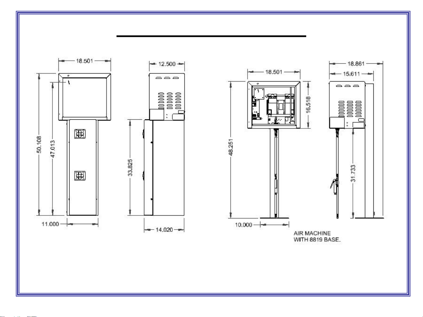
PRODUCT DIMENSIONS
.
* For compressor less units air supply to be routed by customer to solenoid inside air machine*
AIR/WATER MACHINE
WITH 6025-DIG BASE.
REV 3-23-22
Table of contents
Other J.E. Adams Industrial Equipment manuals


