J.E. Adams M24B User manual
Models- M24B & M30B Vacuum Producer
Page 2 Product Information
Page 3 Safety Instructions
Page 4 - 5 Receiving, Handling & Storage
Page 5 - 8 Installation Steps
Page 8 - 9 Pre-Startup Checks/First Startup
Page 10 Operating Temperatures
Page 11 -13 Coupler Alignment
Page 14 -17 Lubrication/ Bearing Replacement
Page 18 –19 Setting Butterfly Intake Valve
Page 20 -24 Surge and Motor Control Options
Page 25 - 34 Optional VFD and Transducer Set-up
REV 06/23/23 1

PRODUCT INFORMATION
Please take a moment to fill out the information below in order to aid us with any future sales or service
inquiries. Model number and serial number information can be found on the serial tag located
inside the control box and/or on the lower exterior of the can. Key number can be found on the tag
that comes attached to the keys. There may be more than one key number depending on unit.
Please keep this information with your records.
MODEL#:____________________________
ORDER#:____________________________
SERIAL#:____________________________
DATE PURCHASED:___________________
MOTOR F.L.A_______________ MOTOR NO LOAD AMPS____________
J.E. Adams Industries
1025 63rd Ave. S.W.
Cedar Rapids, IA 52404
1-800-553-8861
www.jeadams.com
REV 06/23/23 2

IMPORTANT SAFETY INSTRUCTIONS
When using an electrical appliance, basic precautions should always be followed, including the following:
READ ALL INSTRUCTIONS BEFORE USING (THIS APPLIANCE)
WARNING –To reduce the risk of fire, electric shock, or injury:
•Do not use on wet surfaces.
•Use only as described in manual. Use only manufactures recommended attachments.
•Do not allow to be used as a toy. Close attention is necessary when used by or near children.
•Do not put any object into openings. Do not use with any opening blocked; keep free of dust, lint, hair and anything that may reduce air
flow.
•Keep hair, loose clothing, fingers, and all parts of body away from openings and moving parts.
•Do not use to pick up flammable or combustible liquids, such as gasoline, or use in areas where they may be present.
•Do not pick up anything that is burning or smoking, such as cigarettes, matches, or hot ashes.
•Do not use without dust bag and/or filters in place.
SAVE THESE INSTRUCTIONS
•Installation Instructions:
•Determine location to mount unit (“DANGER” “THIS EQUIPMENT INCORPORATES PARTS SUCH AS SWITCHES, MOTORS, OR THE LIKE
THAT TEND TO PRODUCE ARCS OR SPARKS THAT CAN CAUSE AN EXPLOSION. WHEN LOCATED IN GASOLINE-DISPENSING AND
SERVICE STATIONS INSTALL AND USE AT LEAST 20 FEET (6 M) HORIZONTALLY FROM THE EXTERIOR ENCLOSURE OF ANY DISPENSING
PUMP AND AT LEAST 18 INCHES (450 MM) ABOVE A DRIVEWAY OR GROUND LEVEL.”
•Run electrical service to that location
•Grounding Instructions: This appliance must be connected to a grounded metal, permanent wiring system; or an equipment-grounding
conductor must be run with the circuit conductors and connected to the equipment-grounding terminal or lead on the appliance.
•All local and national electric codes must be followed for installation and use.
•Licensed electricians are recommended for installation.
REV 06/23/23 3
Receiving and Storage
RECEIVING OF UNIT:
Immediately upon receipt, thoroughly examine the equipment. Both motor and blower shafts should rotate freely. There should be no evidence
of damage, dented steel, or any other unusual observations. Check the packing list to verify that the shipment is complete, noting receipt of
miscellaneous items in crates or boxes. If any damage has occurred, or any material is missing, make a note on the carrier’s freight bill and
make sure that the driver signs on the same receiving copy. Notify the delivering carrier at once and also notify JE Adams immediately.
•Thank you for your purchase of a JE Adams Vacuum Producer fabricated steel multi stage centrifugal unit.
•Please take the time to review this manual in its entirety to assure that you are familiar with all the requirements and features of your
equipment. Proper installation, operation and maintenance will assure the user of years of trouble-free service. Always refer to your specific
model number and serial number, which are stamped on the nameplate attached to the inlet head.
•Our ongoing commitment to your satisfaction begins with the proper handling and installation of your new equipment.
Warning! Failure to follow good safety practices when handling the vacuum
producer could result in injury or death!
REV 06/23/23
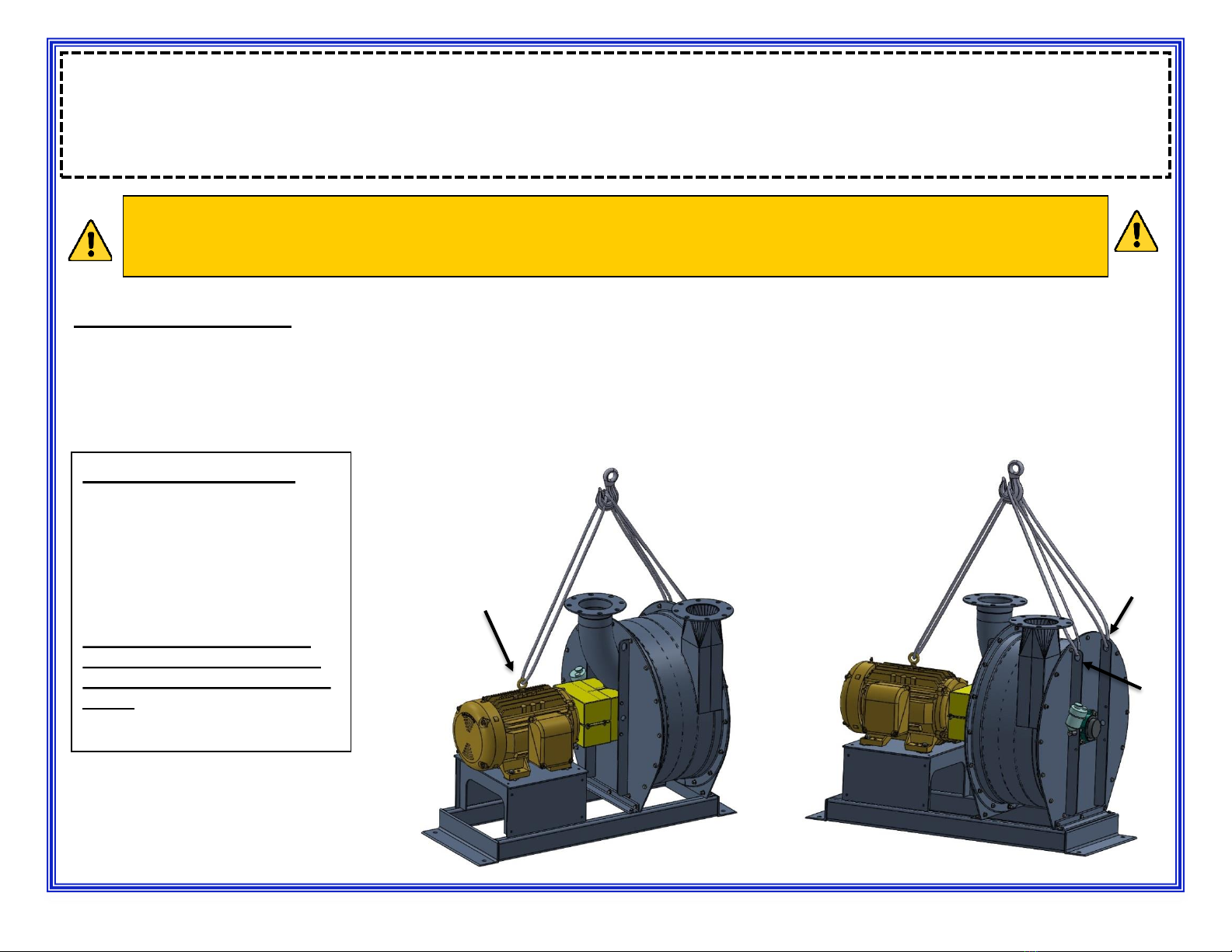
HANDLING OF UNIT:
Your blower/exhauster is
provided with 2 lifting eyes
located on the inlet and outlet
head. We recommend a 3-point
lifting method by using the 2
lifting eyes on the unit and the
one lifting eye on the motor.
DO NOT LIFT BY SHAFT OR
BEARING HOUSINGS. AVOID
BENDING OR DISTORTING OF
BASE.
4
STORAGE OF UNIT:
If your blower/exhauster is not going to be installed for a period of up to 90 days then you must store it in a clean, dry, well-ventilated area. The
unit must be covered and kept out of the elements. Plastic or canvas is preferred. Rotation of the motor unit shaft should be done at least
once a week to redistribute bearing lubricant and prevent bearing damage. Keep a log of shaft rotation to ensure machine warranty protection.
If the storage of your blower/exhauster is longer than 90 days, then in addition to the above storage information, you will need to: suspend a bag
of silica gel in the inlet and outlet heads to absorb excess moisture, coat exposed machine surfaces with a protective grease and follow
motor manufactures instructions so that the motor is properly maintained.
INSTALLATION:
LOCATION:
–Indoor locations are preferable.
–The location selected should be clean, dry, properly drained and adequately ventilated.
–Plan ahead. Ample room is required for maintenance, lubrication and the removal of the machine or driver for servicing.
FOUNDATION:
The blower/exhauster should be located on a solid, level, and flat surface. The best surface is a reinforced concrete slab however; a well
reinforced above grade surface is suitable. Avoid mezzanines or catwalks and hollow floors.
REV 06/23/23
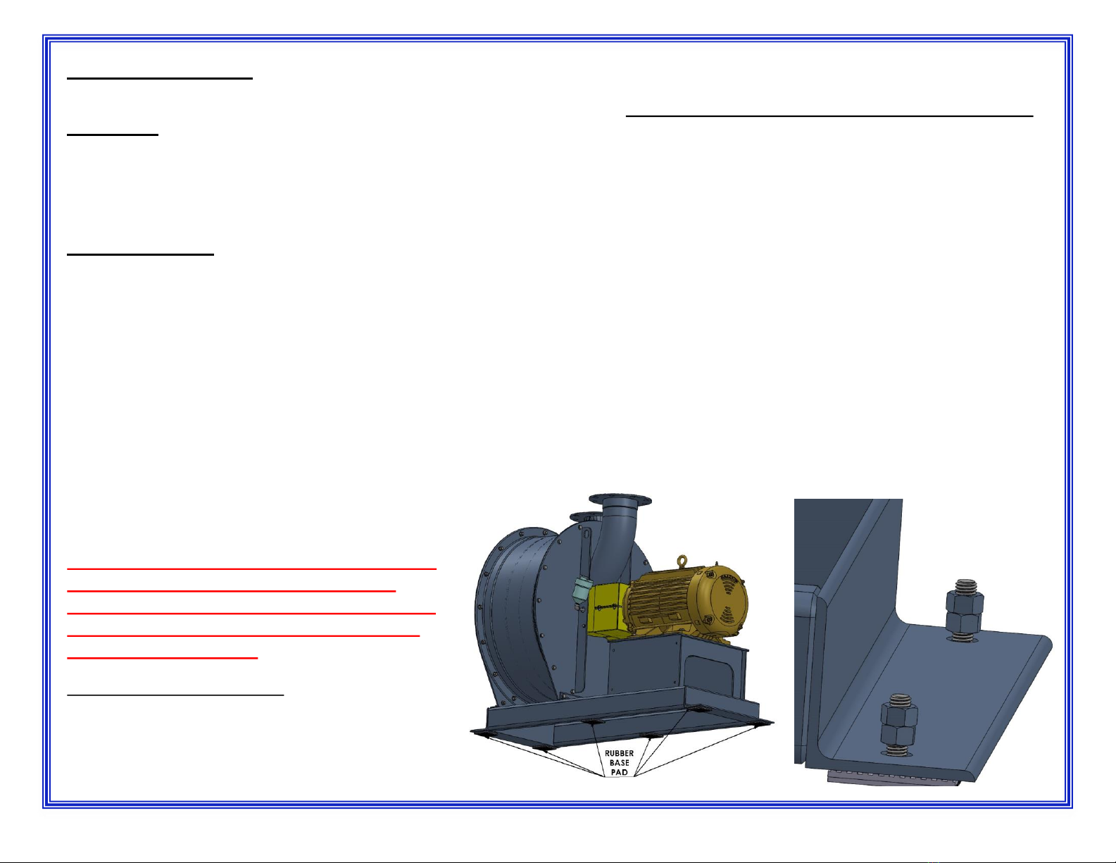
POSITIONING:
Bolt holes are provided for shipping and positioning
purposes as seen in the image below. If floor bolts are
used the NUTS SHOULD NOT TOUCH THE BASE!
NOTE: TIGHTENING MAY DISTORT THE BASE OR
RESTRICT THE BASE PAD MOVEMENT AND
CAUSE EXCESIVE VIBRATION. DO NOT WRENCH
TIGHTEN BASE BOLTS. THIS COULD VOID THE
EQUIPMENT WARRANTY.
Rubber vibration isolation pads have been supplied.
These must be installed under the base as follows:
one under each corner of the unit and one under each
side of the base at approximately the middle of the
unit.
5
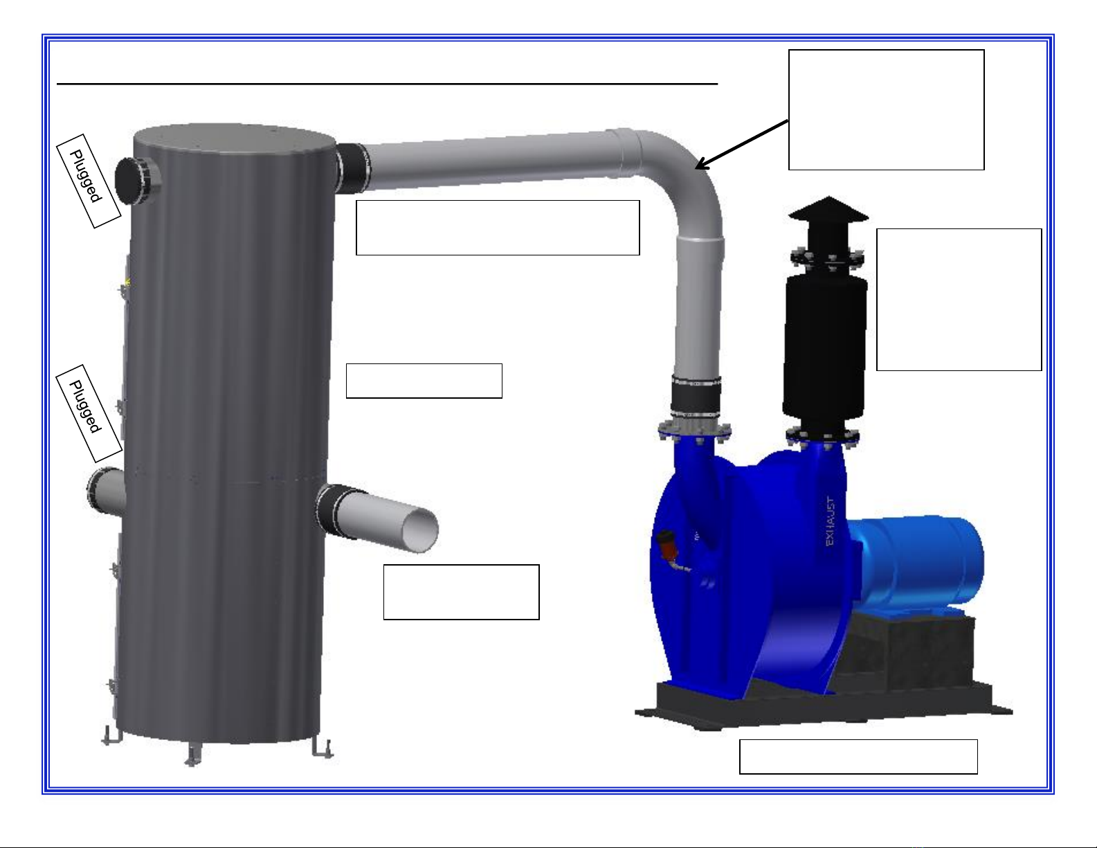
Turbine/Producer and Main Collector Installation example:
Filtered side of collector
connected to inlet of producer
Inlet pipe from
vacuum stations
Main Collector
Producers are
generally
installed inside
buildings, if so
best to route
exhaust outside.
Vacuum Producer/Turbine
REV 06/23/23
Make sure the weight
from piping is well
supported and not
putting strain on the
exhaust outlet.
6
ELECTRICAL
• Read and comply with motor manufacturer’s installation and operation instructions
which are attached to the motor. Make sure that the motor nameplate requirements
agree with the available power supply at job site. All wiring MUST be done by a
licensed electrician (industrial experience preferred) in accordance with the
National Electrical Code (NEC-NFPA 70), and other applicable national and
local regulations.
ELECTRIC MOTOR RECOMMENDATIONS
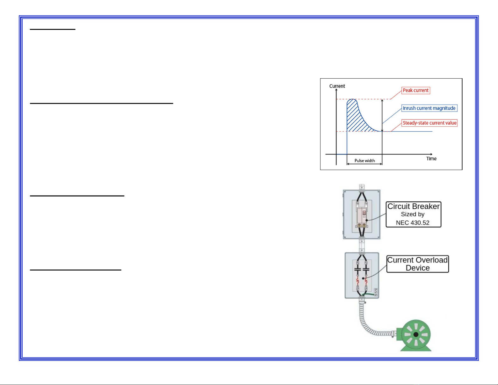
•Every time an electric motor is energized the motor will draw 10-30 times the motor
name plate amps. This initial amperage spike is commonly referred to as the
“inrush current” and typically only lasts a few seconds until the motor can reach the
normal operating current or what is called “steady state”.
•It is necessary to account for the inrush current when installing motors and starters;
to avoid tripping breakers or blowing fuses unnecessarily when the
blower/exhauster is energized. JE Adams recommends following NEC article 430
when installing electric motors.
Electrical Soft Starters
•Electrical soft starters are used reduce the voltage supplied to the motor when it is
energized which reduces the inrush current. The voltage is then slowly increased to
the line voltage over several seconds (depending on the soft start this can be up to
30 seconds). Many electrical soft starters monitor current and have settings to
protect the motor from over drawing amperage. Soft starters are sized by the size
motor they are driving and should be installed to the manufactures specifications.
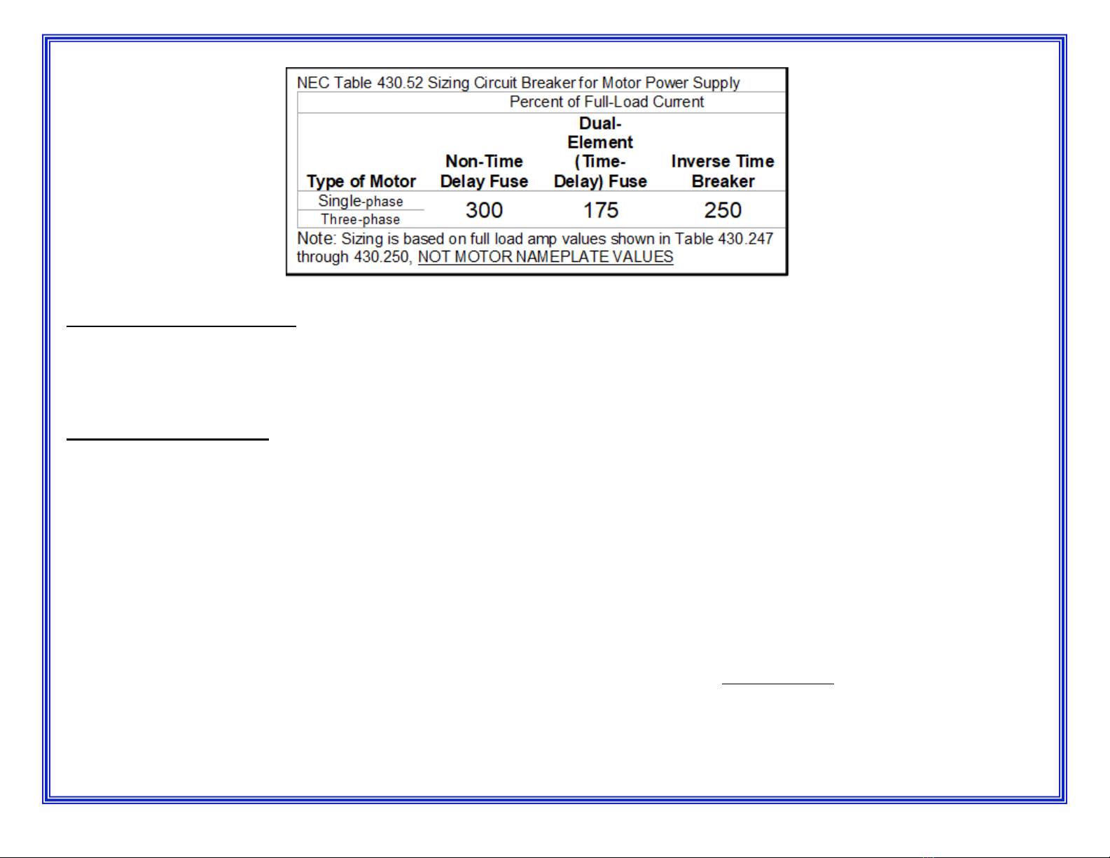
Sizing Circuit Breaker
•Correctly sizing the circuit breaker for a motor is critical to suppling the amount of
current required to start the motor. Due to the inrush current the circuit breaker
should be sized by using NEC code 430.52. Below is a reduced table from NEC
430.52 for reference.
REV 06/23/23 7
Current Overload Device
•JE Adams recommends installing a current overload device to protect the motor. The breaker is oversized allowing the motor to draw the
required current to start the motor but this can leave the motor susceptible to overload under normal operation.
PRE-STARTUPS CHECKS
1) A visible inspection should be done to insure unit is on a solid, flat, level, and smooth foundation with vibration pads installed.
2) Check motor connection to make sure it is wired properly. Refer to motor nameplate and control panel connections per electrical drawings. If
additional items such as: temperature sensors, surge controls, vibrations switch’s etc. have been provided then these must be correctly wired
per manufacturer’s instructions.
3) Check for and remove any foreign material that might be located in the intake or discharge piping.
4) Remove coupling guard and recheck coupling alignment. The blower/exhauster and motor shafts were properly aligned at the factory prior to
shipment. However, rough handling in transit could have disturbed this alignment. Therefore alignment MUST be rechecked and the
unit realigned if necessary. Refer to coupling alignment instructions in the COUPLING ALIGNMENT section of this manual.
5) After alignment has been checked the shaft should be rotated by hand several times to insure that the rotation is free and the unit rotor
assembly does not rub.
6) Your blower/exhauster has been pre-lubricated at the factory. The automatic lubrication system for the blower/exhauster bearings should be
installed as outlined in the following pages of the manual under LUBRICATOR INSTALLATION, before operation. Electrical motor bearings
should be lubricated per manufactures instructions. Owners manuals for the appropriate motor brand and HP size can be found on line.
REV 06/23/23 8

PRE-STARTUPS CHECKS -CONTINUED
7) Bump the power to the motor to ensure that the direction of rotation agrees with sticker on the inlet head. The direction of rotation may be
observed on many TEFC motors by watching the cooling fan at the end of the motor. (This will allow the coupling guard to be reinstalled for this
check.) NOTE: CAUTION SHOULD BE OBSERVED TO KEEP HANDS, FEET AND ANY LOOSE CLOTHING AWAY FROM THIS
ROTATING EQUIPMENT. THE COUPLING GUARD IS ONLY REMOVED TO CHECK ALIGNMENT AND ROTATION IF ROTATION CAN
NOT BE OBSERVED IN ANOTHER LOCATION. NEVER OPERATE THIS EQUIPMENT WITHOUT THE COUPLING GRARD SECURELY
BOLTED IN PLACE.
8) Restricting the flow of air into or out of your blower/exhauster will help reduce the high amperage draw time of the motor on start-up. If your
blower/exhauster does not have a butterfly intake valve built into the inlet, check the piping entering and exiting the blower/exhauster for a valve
to close and restrict the air flow.
Note: It will take about 20 seconds for the unit to come up to full speed with the air flow restricted.
9) Place an amp meter on one incoming power lead to measure the amp draw.
Note: A true RMS meter is best to measure 3 phase current.
10) If your blower/exhauster is equipped with a butterfly intake valve follow the procedure outlined in the SETTING THE BUTTERFLY INTAKE
VALVE section of the manual before proceeding with step 11.
11) After setting the butterfly valve, once again start the blower/exhauster and check the amperage reading for FLA.
NEVER EXCEED THE MOTOR F.L.A.!!
NOTE: IF ANY NOISE OR VIBRATION IS DETECTED SHUT THE UNIT DOWN IMMEDIATELY.
12) Allow the unit to run until it has reached full operating temperature. This should take about 15 minutes.
13) Now that the blower/exhauster is running check for unusual noises and vibration.
14) Now that the blower/exhauster is running a check should be made on any on the operation of any optional item such as: surge protection
device, surge prevention device, bearing temperature devices etc. Refer to individual operating instructions sheet for each specific item.
REV 06/23/23 9

OPERATION STANDARDS
Although it may vary depending on size of unit and application, normal operating levels are:
Vibration: Less than .24 in/sec (6.1 mm/sec) in the vertical plane at each bearing.
Note: Vibration is measured at operating speed with air flowing through the machine.
Temperature Range Inlet = 85°F to 120°F (29°C to 49°C)
Outlet = 170°F to 235°F (77°C to 113°C)
OPERATING TEMPERATURES
It is the nature of centrifugal compressors to run hot due to heat of compression and internal friction caused by movement of air. The higher
temperatures will be on the discharge side of the machine. The following information will serve as a guide in determining acceptable
temperature limitations under normal operating conditions. For specific applications, or operating temperatures outside of the figures shown,
contact the factory.
BEARING TEMPERATURES
Bearings used in your centrifugal blower are designed to operate continuously in temperatures in excess of 200°F (93°C), measured on the
bearing housing. Standard alarm circuitry, if supplied, is set to alarm at 230°F (110°C). If bearing temperature monitors are not supplied,
check bearing housing temperatures, periodically, and notify JE Adams if readings exceed 220°F (104°C).
DISCHARGE AIR TEMPERATURE
Under normal operating conditions, using ambient or atmospheric air, typical discharge air temperatures may also exceed 200°F (93°C)
measured in the discharge air stream or on the surface of the discharge (outlet) head. Discharge temperature is affected by many factors
including efficiency, flow, pressure, altitude, inlet temperature etc. so it is difficult to determine the exact discharge temperature to expect.
Generally speaking, the discharge air temperature should not exceed 275°F (135°C) under normal operating conditions. In all cases where
other than ambient or atmospheric air is being compressed, or discharge temperatures reach 275°F (135°C), consult factory. Failure to do so
could nullify factory warranty.
Blower and motor surfaces can remain hot for an extended period of time after equipment shut down. Exercise caution
when working on or around this equipment when hot.
REV 06/23/23 10
A NOTE ON NOISE...
Every effort has been made to keep the noise level of operating equipment below 85dBA, the current acceptable limit mandated by OSHA.
Although hearing protection in not required by law, the manufacturer suggests the use of hearing protection when operating or working around
this equipment.
COUPLING ALIGNMENT
- The following procedure is applicable to direct driven machines only. Correct alignment will ensure a longer life and trouble free operation of
you blower/exhauster. REALIGNMENT AFTER INSTALLATION MUST BE DONE.
- Damage to equipment due to improper alignment is not covered by your equipment warranty.
- Misalignment is one of the most common causes of unit vibration and will cause premature bearing failure.
FINAL SHAFT ALIGNMENT IS THE RESPONSIBILITY OF THE INSTALLER/OWNER.
The following conditions can affect alignment and can be a factor in trying to achieve a good alignment.
1) Base and foundation not level and smooth.
2) System piping not isolated with flexible sleeve or expansion joint.
3) Blower/exhauster base not mounted on vibration pads.
4) Blower/exhauster bolted down.
NOTE: LACK OF VIBRATION ON START-UP DOES NOT INDICATE THAT THE UNIT IS IN PERFECT
ALIGNMENT.
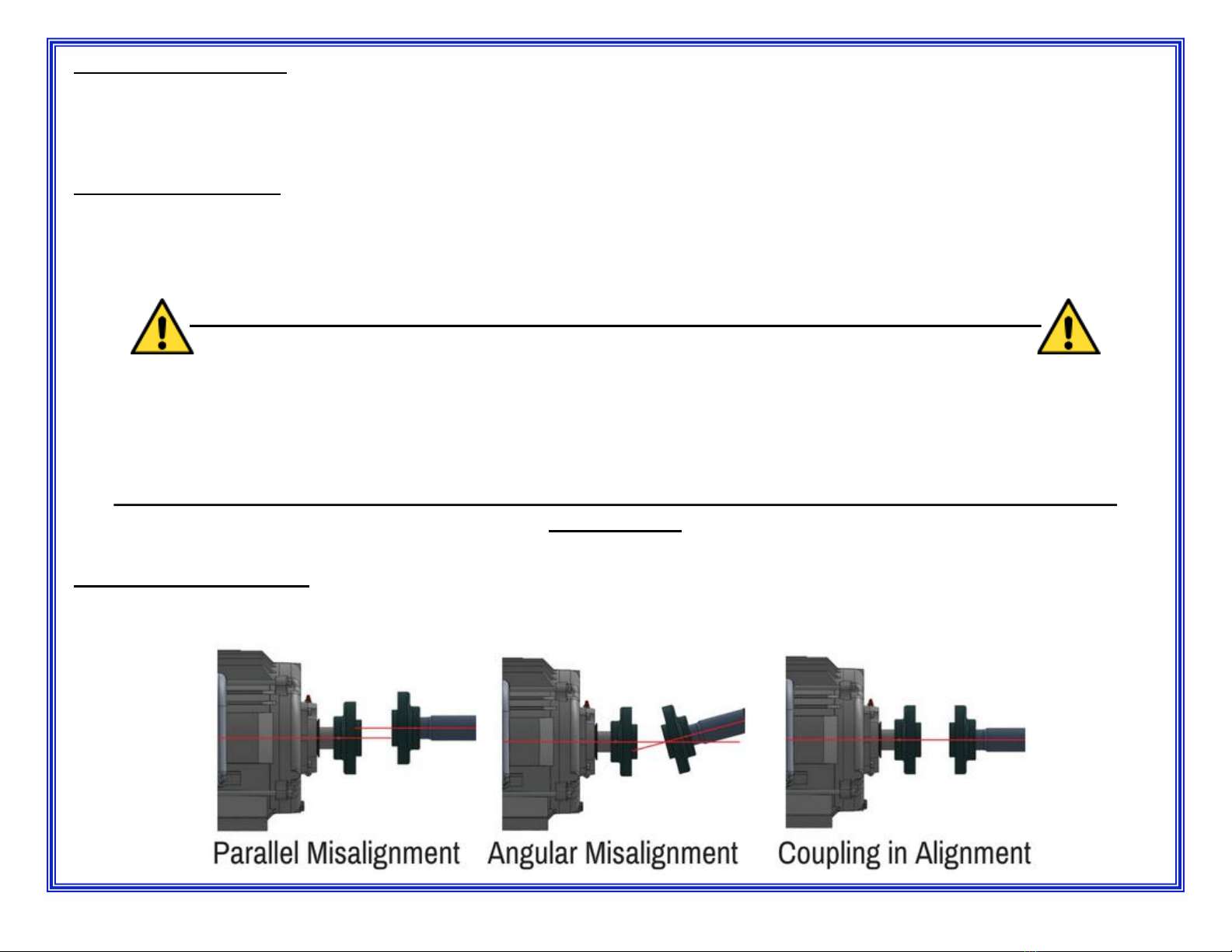
TYPES OF MISALIGNMENT:
Misalignment can occur as either parallel or as an angular displacement on two of the three possible axes. The manufacturer recommended
alignment tolerance is +/- .005 inches parallel and .250 degree angular.
REV 06/23/23 11
Alignment can be done by several different methods:
1) Laser Alignment - is the most accurate and quickest method.
2) Dial Indicator Methods
–Reverse Dial Indicator Method
–Single Dial Indicator or Rim and Face Alignment
TOOLS NEEDED FOR ALIGNMENT
- Calipers
- Dial Indicator
- Straight Edge
-6” Level
REV 06/23/23
ROUGH ALIGNMENT:
A rough alignment may be necessary due to the range limitations of the dial indicators. The simplest method is to
use a straight edge and calipers to bring the machines into rough alignment. Place a straight edge across the
outside diameters (O.D.) of the coupling hubs at 90-degree intervals to check and correct the parallel misalignment.
Use the calipers to check and correct the angular misalignment. The calipers should be used at the same 90
degree intervals as the straight edge.
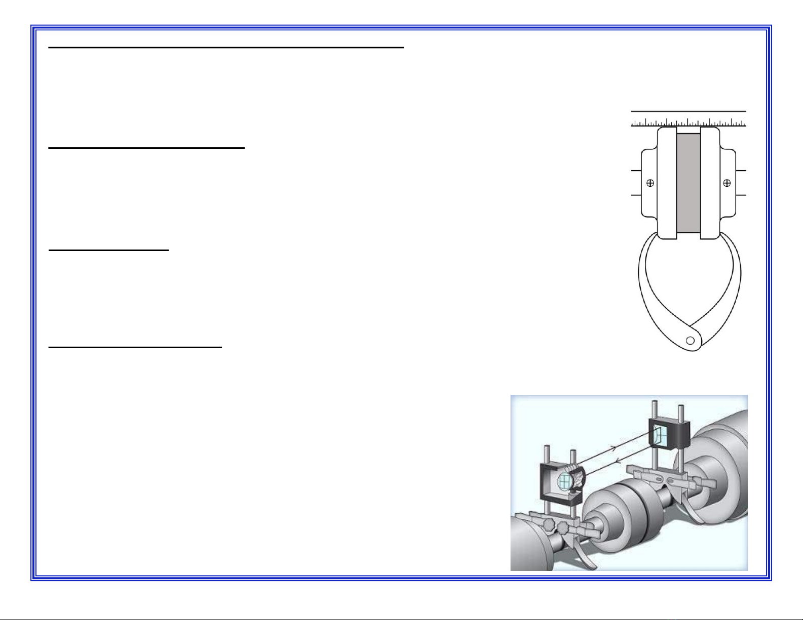
LASER ALIGNMENT METHOD:
The laser alignment method uses a laser to span the shaft-to-shaft distance. As both shafts are rotated together the
misalignment is determined by the movement of the laser beam on the detector surface. The laser is connected to
a computer to that displays the misalignment and the amount of correction needed. This is the most accurate
method available and is the recommended method for the vacuum producer.
12
REVERSE DIAL INDICTOR METHOD:
The reverse dial method is similar to the laser alignment method, however, less
accurate and can take more time. This method also takes shaft-to-shaft readings but
uses two dial indicators instead of a laser for measurement. As both shafts are rotated
together, both the parallel and angular misalignment are combined in one indicator
reading. This method will require the use of two special brackets to hold the indicators
during the measurements.
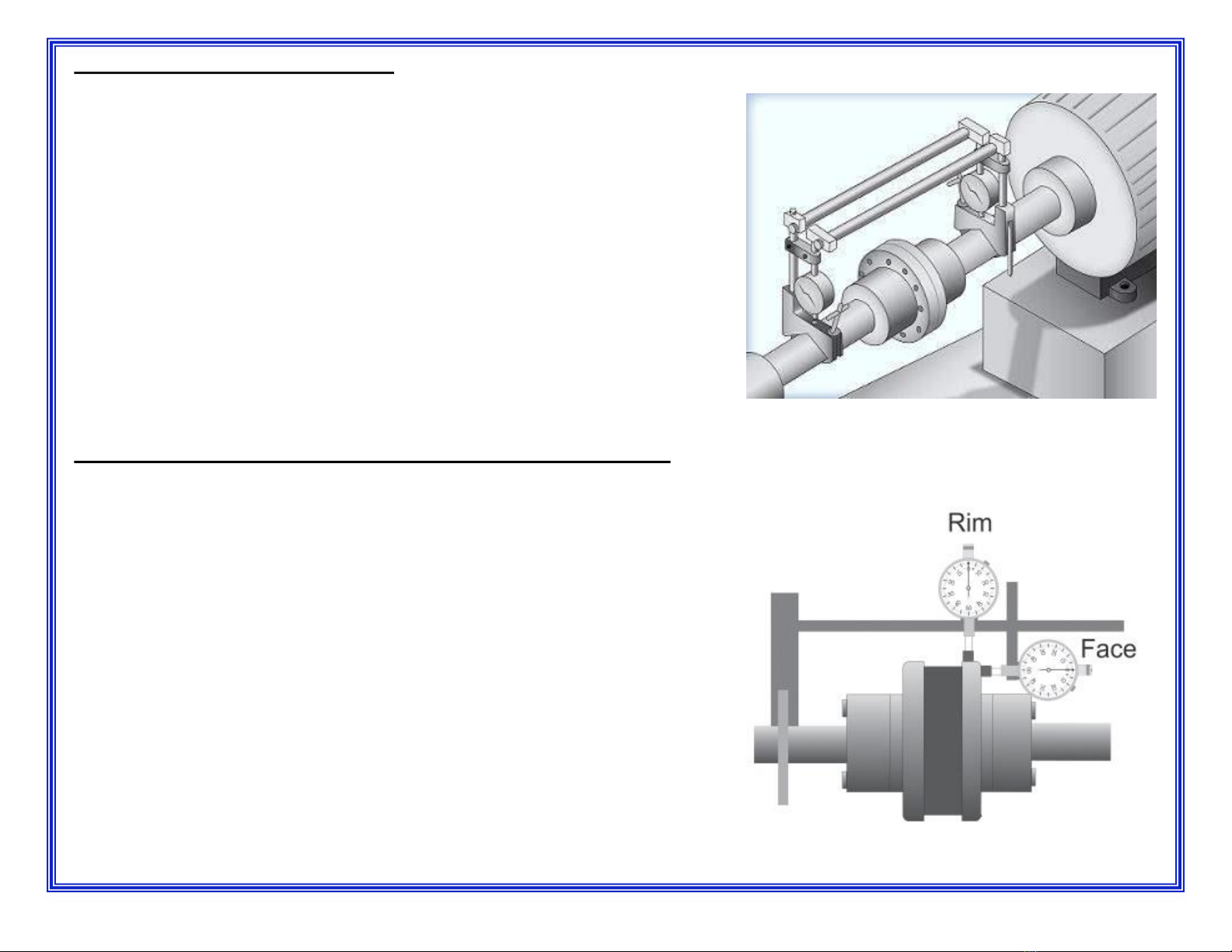
SINGLE DIAL INDICATOR OR RIM AND FACE ALIGNMENT METHOD:
This method is similar to the rough alignment but more accurate since dial indicators
are used. The rim reading measures the offset between the coupling halves. The face
reading measures the angular difference between the faces of the coupling.
The procedure is as follows -
1) Clamp dial indicator on driving (Motor) side of coupling and locate the indicator
probe on the rim (O.D.) of the driven (Blower) coupling half. Rotate shaft and take
reading at 90-degree intervals to determine the amount of parallel misalignment.
Misalignment of coupling is ½ of Total Indicator Reading (TIR).
2) Locate indicator probe at the extreme point on the coupling face, rotate shaft and
take readings at 180-degree intervals to correct any angular misalignment.
3) Once the angular misalignment has been corrected be sure to re-check the rim
alignment to ensure it is still correct.
REV 06/23/23 13
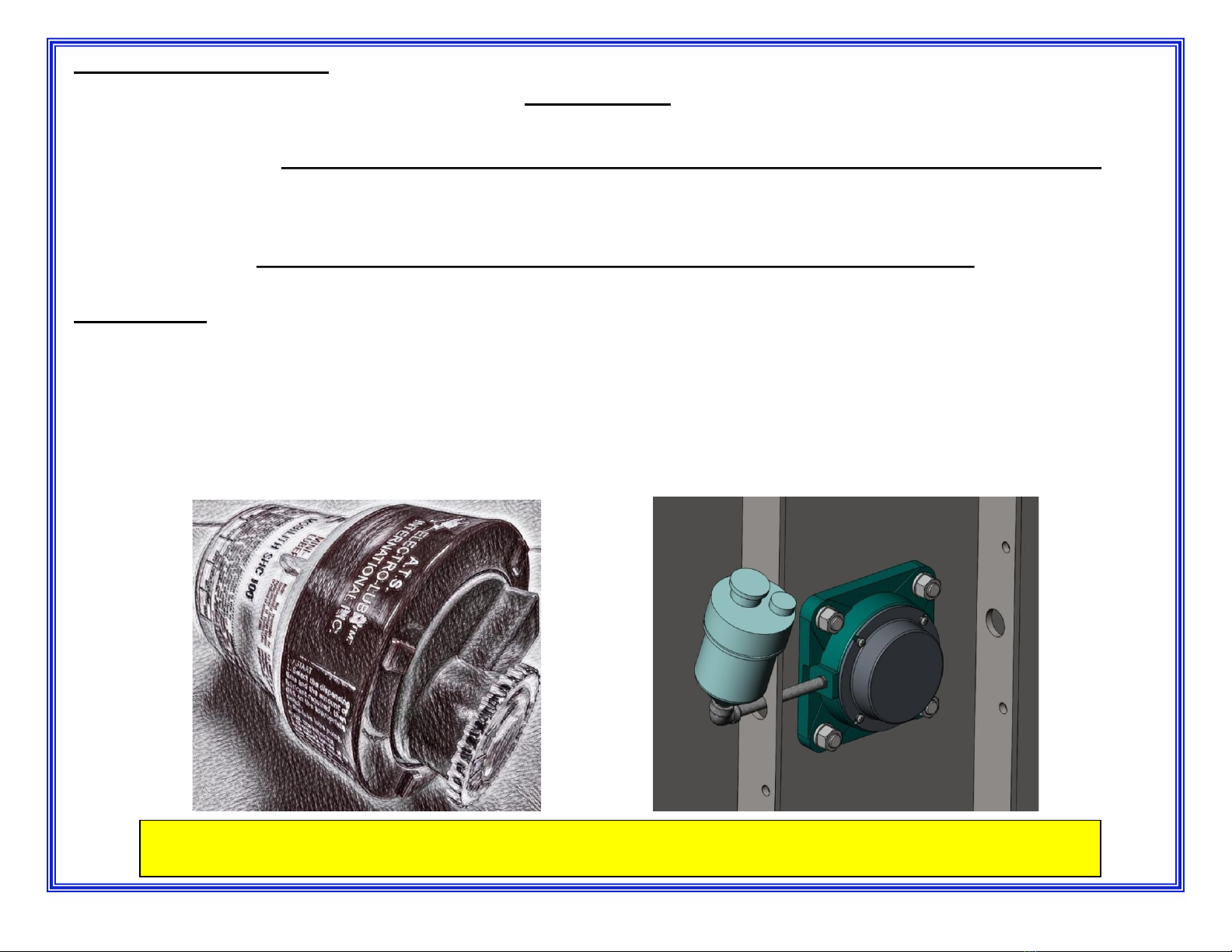
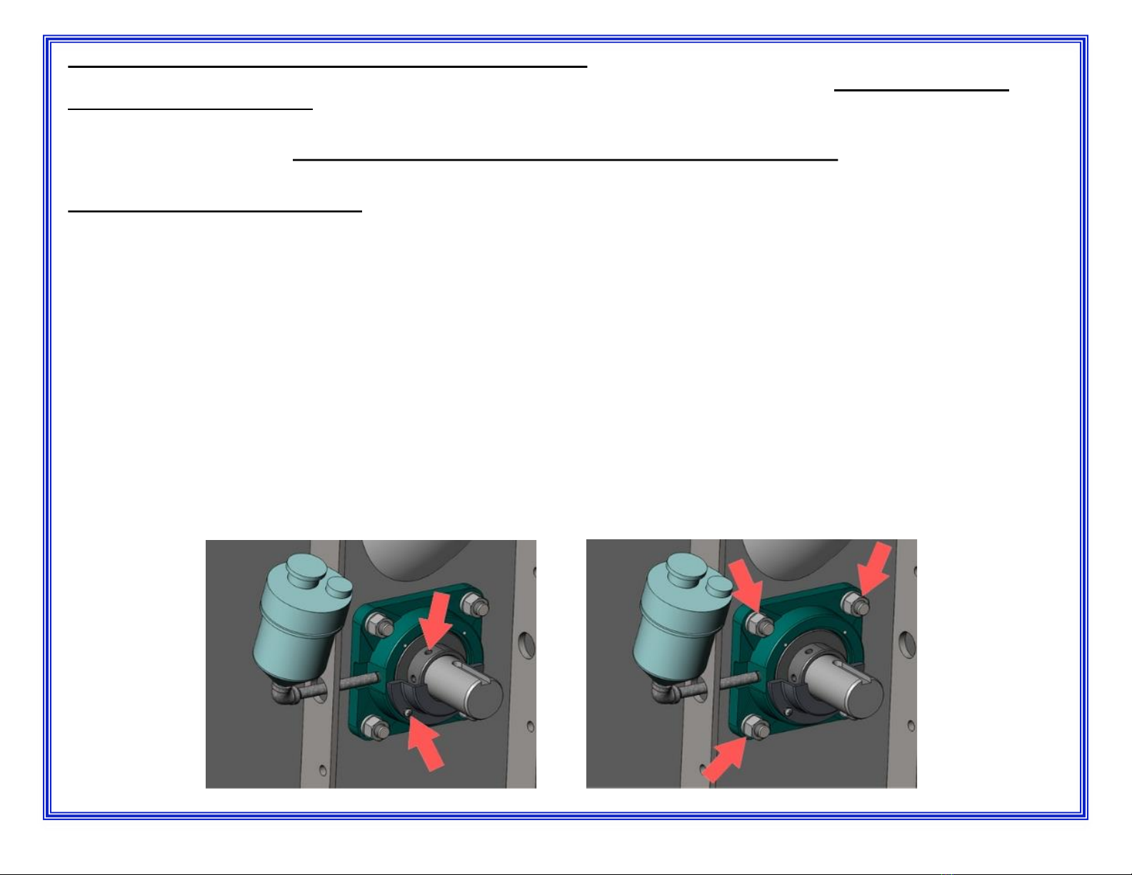
LUBRICATOR INSTALLATION
Your JE Adams unit is supplied with electronic lubricators, P/N 35000-192. When the selector switches are moved from the off to the on
position an electro-chemical reactor cell is activated. This begins an electro-chemical reaction whereby electrical energy is converted into
nitrogen gas. As the gas is generated and captured in a set of bellows, the pressure is used to move a piston. The piston forces the grease out
of the end of the lubricator. The electronic lubricator is not designed to be recharged or refilled and is one time use part.
The electronic lubricators are shipped loose to prevent any possible damage in transit.
INSTALLATION OF THESE (Qty 2) MUST BE DONE BEFORE START-UP OF EQUIPMENT.
INSTALLATION:
When you receive your JE Adams centrifugal vacuum producer it will be necessary to install both of the automatic lubricators to provide the
proper amount of lubrication to the bearings. The process is as follows:
1) Remove to cap on the electronic lubricator that protects the ¼” NPT thread.
2) The bearing has been plugged to prevent any foreign material from entering the grease during shipment. Remove the plug in the elbow.
3) Thread the automatic lubricator into the elbow, hand tight, being careful not to overtighten.
4) Once the lubricators have been installed in both bearings it will be necessary to set the rate that they dispense the lubricant
REV 06/23/23
REPLACE AUTO-LUBERS ONCE A YEAR!!
Replacement auto-lubers (35000-192) are available through JE Adams Industries, 1-800-553-8861
14
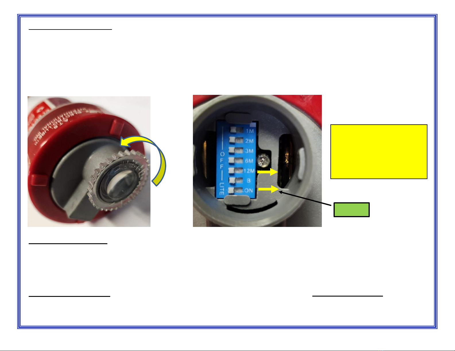
STARTING AND SETTING:
After installation of the automatic lubricators remove the switch cover by rotating the cover cap off, in the direction the arrow next to the word
“OPEN” indicates. With a pencil, slide ONLY the dip switch marked “12M” from the “OFF” position to the “ON” position. The 12M setting will
provide you with a 1-year supply of lubricant.
If a visual indicator of operation is desired then you can slide the switch marked “LITE” from the off position to the on position. This will activate
a LED light that will flash every 15 seconds and indicate that the unit is in operation and producing the required gas to displace the grease. It
will take about 10 days for the lubricant to begin to flow. Your turbine has been provided with pre-lubricated bearings to allow for this time lag.
MANUAL LUBRICATION:
JE Adams provides automatic lubricators for all series blowers and exhausters equipped with 4 bolt flange bearing. The manufacturer of these
bearings has stated “a small amount of grease at frequent intervals is preferable to a large amount at infrequent intervals”. This is the preferred
method of lubrication, however automatic lubricators have to be replaced every 9-12 months, depending on use.
If lubricating manually is preferred (we do not recommend), install a zerk grease fitting where the automatic lubricators is screwed into the
elbow. The bearing should be greased at the interval outlined in the section below.
Do not mix greases!! The JE Adams vacuum producer uses a proprietary Centron B grease –PLEASE CONTACT US!
Mixing grease types can cause the grease to break down due to chemical incompatibility and will result in rapid bearing failure. BEARING
FAILURE DUE TO THE USE OF INCORRECT GREASE IS NOT COVERED BY YOUR EQUIPMENT WARRANTY.
REV 06/23/23
OPTIONAL
REPLACEAUTO-LUBERS
ONCE A YEAR!!
Replacement auto-lubers
(35000-192) are available
through JE Adams
Industries, 1-800-553-8861
15
REV 06/23/23
MANUAL LUBRICATION INTERVAL
GREASE SPECIFICATIONS -FOR 4BOLT FLANGE BEARING
NGLI GRADE............................................................................................................................................NO. 2
THICKENER TYPE............................................................................................................LITHIUM COMPLEX
OIL...........................................................................................................................................SYNTHETIC OIL
VISCOSITY .............................................................................................................................445 cSt @ 40C
VISCOSITY INDEX.......................................................................................................................................150
DROPPING POINT (ASTM D2265).............................................................................................509F (265C)
CORROSION PROTECTION ...................................................................................................................PASS
TEMPERATURE RANGE................................................................................-40F (-40C) TO 302F (150C)
TEXTURE...........................................................................................................................................SMOOTH
COLOR.......................................................................................................................................................RED
Model
Interval
Grease Amount
M24B
Weekly
3.5 CC
Model
Interval
Grease Amount
M30B
Weekly
4.0 CC
16
BEARING REMOVAL & REPLACEMENT -- (MAINTENANCE ONLY)
When a bearing becomes noisy it should be changed at once. You should change only one bearing at a time!! NEVER REMOVE BOTH
BEARINGS AT THE SAME TIME. THIS WILL CHANGE INTERNAL SETTINGS AND DAMAGE TO ROTOR ASSEMBLY MAY RESULT.
Please note, bearings should always be replaced in pairs.
Procedure to replace bearings:
1) Remove the automatic lubricator and piping from the bearing.
2) Remove the 4 screws that hold the bearing cap to the flange bearing. The cap covers 2 set screws (internal hex head) located in the inner
race of the bearing. These set screws hold the rotor in axial alignment.
3) Remove the 4 nuts holding the bearing to the head. With the hardware removed pull the bearing off shaft.
4) Install new bearing on the shaft and replace the 4 nuts that hold the bearing to the head and tighten them down to the required torque.
5) Remove the set screws from the inner race of the bearing and apply a small amount of medium strength thread locker. Reinstall the set
screws in the inner race and tighten them down to the required torque.
6) Install the bearing cap to cover the set screws.
7) Repeat process for other bearing.
8) Before reinstalling the automatic lubricator piping JE Adams recommends cleaning out any old grease from the piping and refilling the piping
with the lithium grease recommended for the 4 bolt flange bearing.
NOTE: Bearings are approximately 33% filled with lubricant at the factory. No grease should be pumped
into the bearing.
REV 06/23/23 17
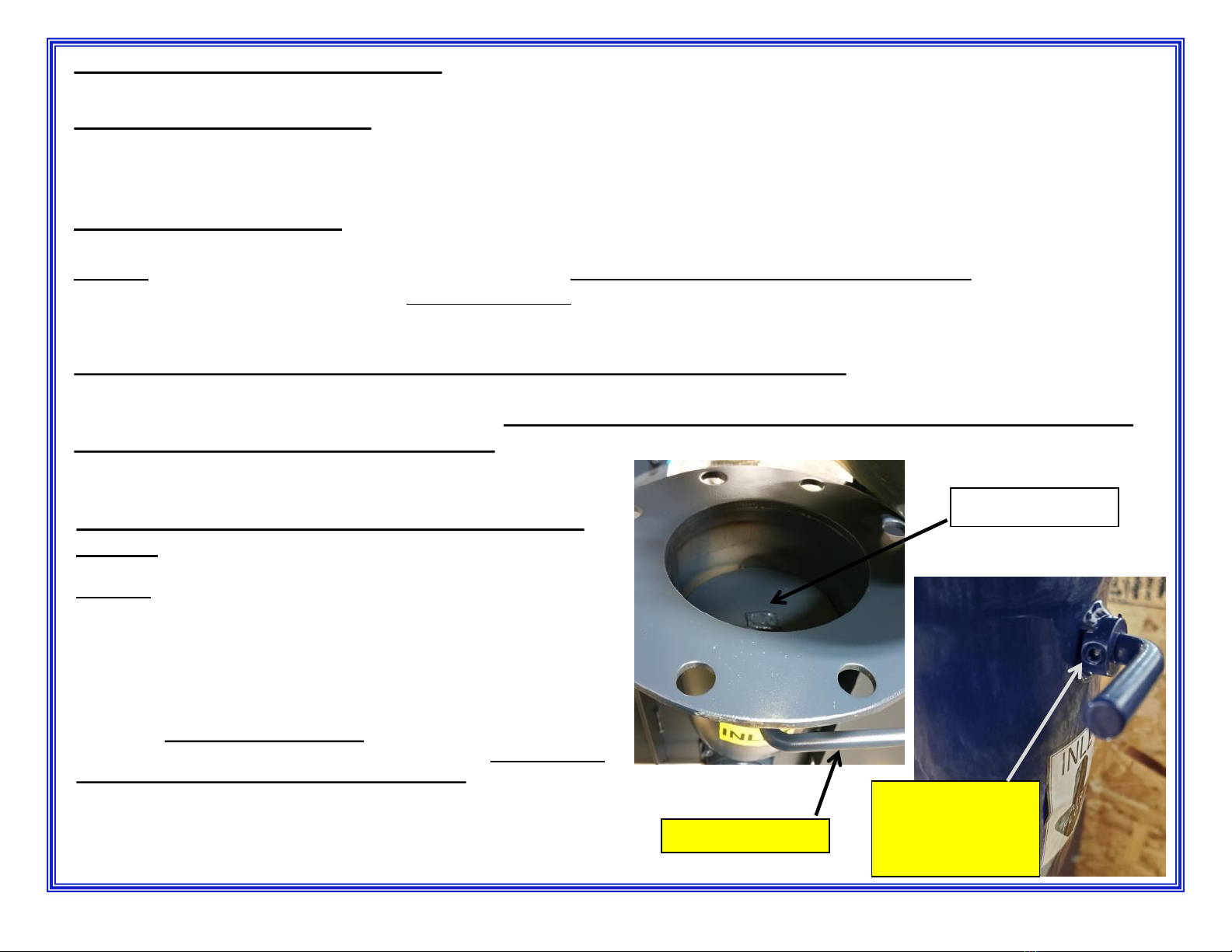
SETTING THE BUTTERFLY INTAKE VALVE
BUTTERFLY VALVE DESCRIPTION
The butterfly valve is used to regulate the air flow through the blower/exhauster. The inlet butterfly valve may be a necessary tool to protect the
motor from drawing more than the full load amps for both blowers and exhausters.
VACUUM SYSTEM LEAK TEST
Purpose: To identify leaks in the vacuum system and establish a no flow amperage baseline for future service inquires.
1) Position the handle on the butterfly valve to the closed position (perpendicular to the inlet tube) –use allen wrench to loosen handle.
2) Place an amp meter on the incoming power leads to measure the amp draw. Note: A true RMS meter will be needed to measure 3 phase
current.
3) Start the exhauster with all the vacuum hoses in their holders and the surge control disabled. Now position the handle on the butterfly
valve to the fully open position (parallel to the inlet tube).
4) Record the no load amps on the cover of this manual. If the system is tight the exhauster will be in surge and should not be ran
in this condition for more than 2 minutes.
5) Shut the exhauster down.
REV 06/23/23
SETTING THE BUTTERFLY INTAKE VALVE ONA VACUUM
SYSTEM:
Purpose: To establish the maximum volume of air the exhauster can
handle within the constraints of the motor.
1) With the vacuum leak test completed and the amp meter still on the
incoming power leads, reposition the handle on the butterfly valve to the
closed position (perpendicular to the inlet tube).
2) Then open the valve about 15-20 degrees to gain some flow (the
handle should be around the 4 o’clock position).
3) Remove **all the vacuum hoses** from their holders and re-enable
the surge control. **System should be at a full draw based on how
many hoses the vacuum producer was sized for. Please consult
your JE Adams sales rep if unsure.
4) Start the exhauster and allow it to come up to full speed (it should
take about 20 seconds). Valve Handle
Two set screws
must be loosened
to adjust (both
sides of inlet)
Butterfly Valve
18
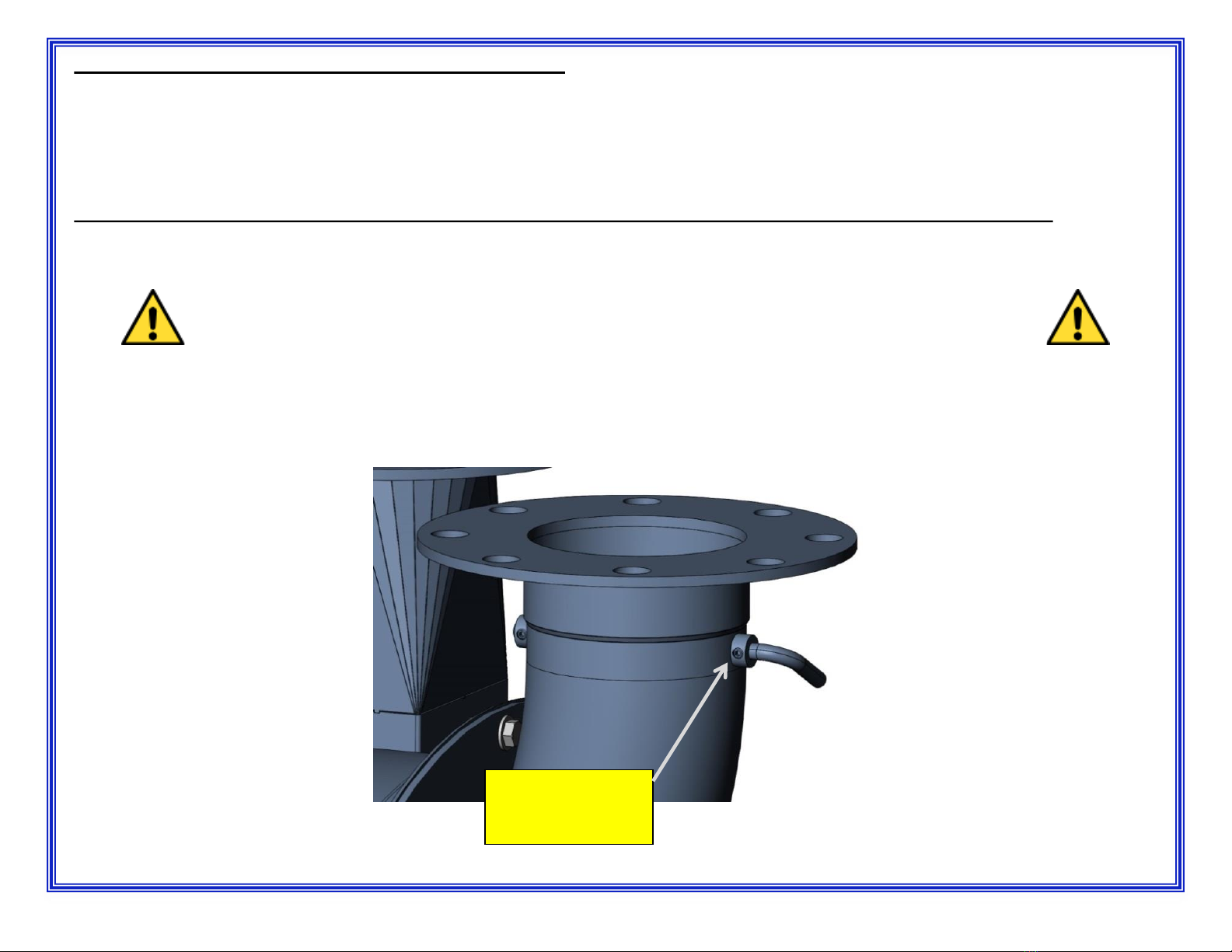
SETTING THE BUTTERFLY INTAKE VALVE -CONTINUED
5) Slowly open the butterfly valve while watching the amp meter. As the exhausters valve is opened the amperage will climb until:
–The motor reaches the full load amps on the name plate of the motor (try to stay under FLA by ½ to 1 full amp).
OR
–The valve is completely open and the exhauster is at its maximum flow.
Once either condition “a” or “b” is met in step 5 tighten the set screw on the collar at the base of the valve to lock it in place.
Note: This procedure may require periodic adjustment if small leaks develop and certainly if more hose drops are added.
NEVER EXCEED THE MOTOR F.L.A.!!
IF ANY DETECTION OF NOISE OR VIBRATION, SHUT UNIT DOWN IMMEADIATLY!!
IF UNIT IS RUNNING IN SURGE, SHUT DOWN WITHIN 2 MINUTES AND CHECK SURGE CONTROL!!
REV 06/23/23
Tighten both set
screws (both sides
of inlet).
19
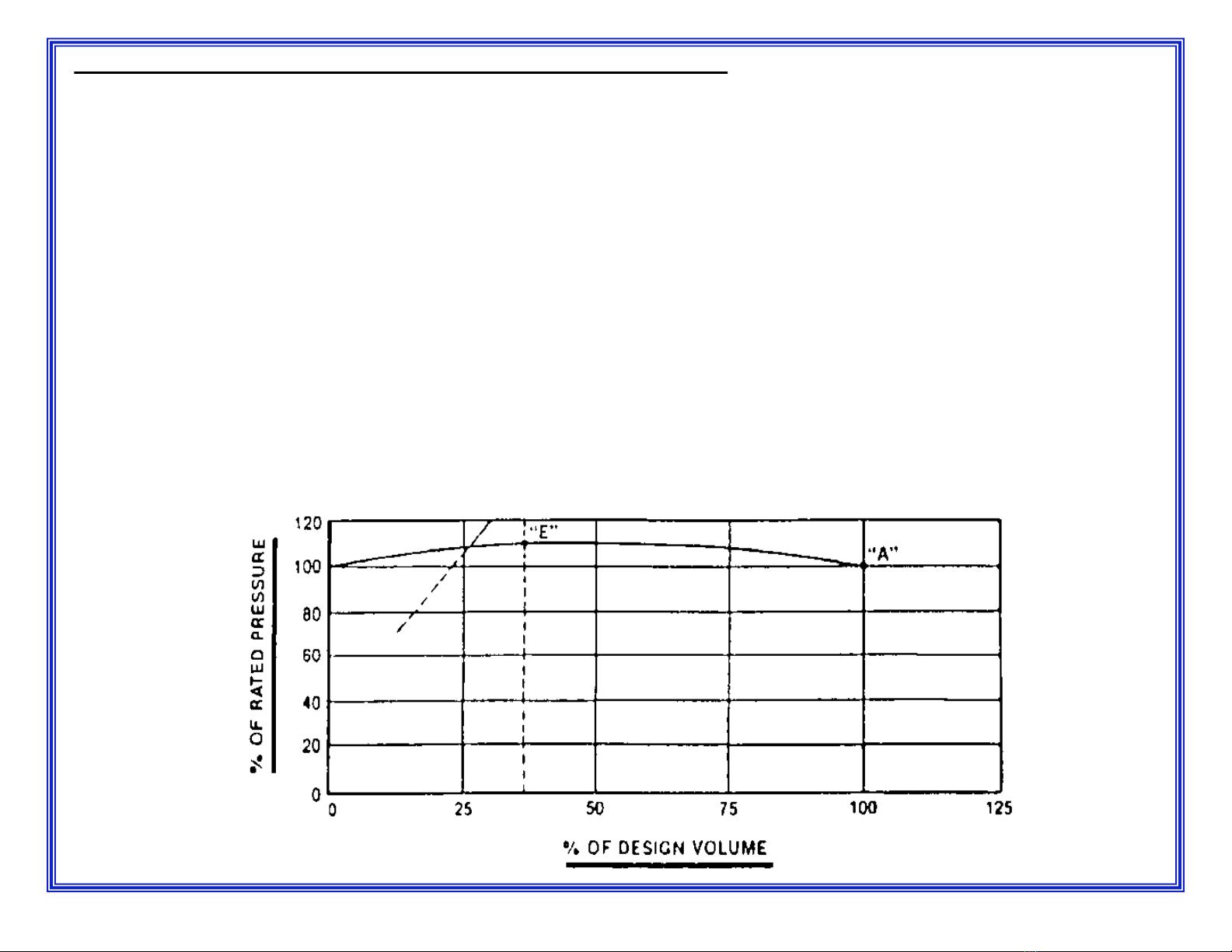
SURGE IN CENTRIFUGAL COMPRESSORS (BLOWERS AND EXHAUSTERS)
A centrifugal blower is normally connected to a piping system and delivers air through that system for ultimate use on some required operation.
If the demand of this operation (and consequently of the piping system) gradually or suddenly decreases, the pressure from the blower and in
the piping system will increase until it reaches the highest pressure peak of which the blower is capable.
If the load or volume requirement (demand) decreases still further, the blower delivery pressure tends to decrease from its peak, resulting in the
pressure in the piping system becoming greater than the pressure from the blower. Air then tends to reverse its direction and flow back into the
blower until both pressures become equalized and the blower can again resume its normal function of pumping air into the system.
Until demand requirements increase, this backward and then forward flow of air –this pulsation or surge –will continue. It can cause undue
strains on the blower and possibly failure of bearings and/or rotating assembly due to repetitive thrust strain and overheating. It is
costly and dangerous to permit volume (load) requirements to drop so low as to cause surge.
Perhaps the foregoing will be more easily understood by reference to the sketch below, which is a typical pressure volume curve of a
centrifugal blower. Point “A” indicates the normal operating point of a blower. Point “E” is the high point on the curve. Stable conditions will
always be experienced when the volume demand is to the right of this point. Under actual operation, surge is not a factor until the volume
demand of the system drops to a point to the left of point “E”, and until pressure consequently drops below that at point “E”.
The frequency and intensity of pulsation or surge depend upon the slope of the characteristic curve of the blower involved, the rate at which the
air is being removed, the pressure in the blower, and the volume of the piping system to which the blower is delivering air. Backward curved
impellers have a lower volume than units with radial vane impellers. Occasionally a blower will deliver air to a system so balanced that
resonance occurs; in this case, even a slight surge will build up forces to significant amounts.
These same principles apply whether a centrifugal unit is operating as a blower or an exhauster.
The approximate surge point is commonly shown on blower and exhauster performance curves as the first data volume point.
REV 06/23/23 20
This manual suits for next models
1
Table of contents
Other J.E. Adams Industrial Equipment manuals


