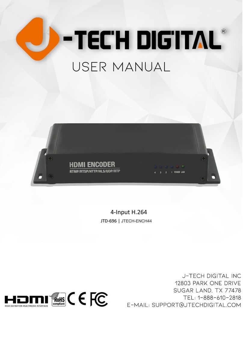
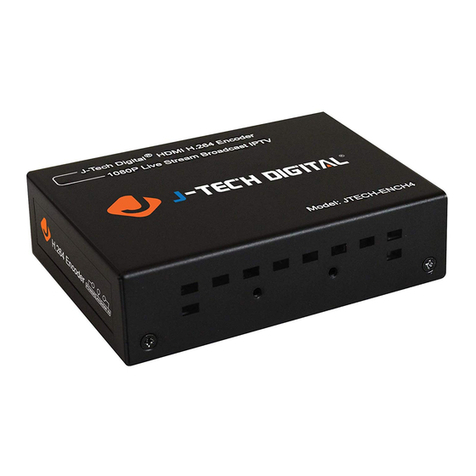
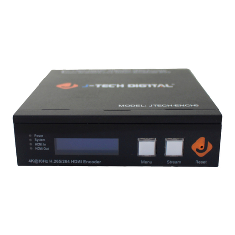
J-Tech Digital JTD-671 User manual

1 | P a g e
JTD-671 | JTECH-ENCH54
4-Input H.264 H.265 Encoder

2 | P a g e
TABLE OF CONTENTS
FEATURES ..........................................................................................................................................4
PACKAGE CONTENTS..........................................................................................................................4
HARDWARE DESCRIPTION..................................................................................................................5
FRONT PANEL...........................................................................................................................................5
BACK PANEL.............................................................................................................................................5
TYPICAL APPLICATION........................................................................................................................6
CONNECTION CONFIGURATION .........................................................................................................7
COMMUNICATING WITH THE JTECH-ENCH54 H.264|H.265 ENCODER ...........................................................7
ASSIGNING THE H.264 |H.265 ENCODER A STATIC IP ADDRESS.....................................................................12
DETERMINING THE IP SCHEME OF YOUR NETWORK –WINDOWS ................................................12
LOCATING AN UNUSED IP ADDRESS ON YOUR NETWORK .............................................................13
ASSIGNING THE JTECH-ENCH54 A STATIC IP ADDRESS IN THE WEB GUI .......................................15
NAVIGATING THE JTECH-ENCH54 WEB GUI......................................................................................21
STATUS MENU........................................................................................................................................21
Device Status Information..............................................................................................................21
Input Port 1 –Input Status | Main Stream URLs ............................................................................22
INPUT PORT 1–4MENU .........................................................................................................................24
Encoder (Main Stream –Substream 3)...........................................................................................24
OSD (Main Stream –Substream 3).................................................................................................25
Logo Upload ...................................................................................................................................27
Video ..............................................................................................................................................28
Audio ..............................................................................................................................................29
ONVIF Audio ...................................................................................................................................30
3 | P a g e
SYSTEM.................................................................................................................................................30
Network..........................................................................................................................................30

Advanced........................................................................................................................................31
Change Password ...........................................................................................................................32
Serial to TCP ...................................................................................................................................33
Upgrade and Backup......................................................................................................................33
Reset...............................................................................................................................................33
Reboot............................................................................................................................................33
Schedule Restart.............................................................................................................................33

4 | P a g e
Dear Customer
Thank you for purchasing the JTECH-ENCH54. For optimum performance and safety, please read
these instructions carefully before connecting, operating or adjusting this product. Please keep
this manual for future reference.
FEATURES
•Supports H.264 & H.265 Encoding
•Supports UDP, HTTP, RTSP, RTMP, ONVIF Protocols
•CBR/VBR Rate: 32 Kbps –32 Mbps
•1000M Network Interface uses Full Duplex Mode
•Supports up to 4K 30Hz HD Video Input
•Supports Image Parameter Settings
•Supports Remote Management in WAN (webGUI)
•Supports Customized Resolution Settings
PACKAGE CONTENTS
1) J-Tech Digital JTECH-ENCH54 H.264/H.265 Encoder
2) Power Adapter 12VDC 1A
3) User Manual

5 | P a g e
HARDWARE DESCRIPTION
Front Panel
1) HDMI Inputs 1-4 Status LEDs
2) Power Status LED
3) LAN Status LED
Back Panel
1) Reset Button (Factory Default Settings –Press & hold the reset button for 10 seconds
until the Power and LAN Status LEDs turn off)
2) Analog Audio Input Ports 1 & 2
3) HDMI Input Ports 1 –4
4) LAN Port (Default IP: 192.168.1.168)
5) DC12V Power Adapter Port
❶
❷
❸
❶
❷
❸
❹
❺

6 | P a g e
TYPICAL APPLICATION

7 | P a g e
CONNECTION CONFIGURATION
Communicating with the JTECH-ENCH54 H.264|H.265
Encoder
You will need to utilize your computer's ethernet port in order to communicate with the
encoder.
CHANGING YOUR PC’S IP ADDRESS
You will start by changing the IP address of your computer to match the default IP address
scheme of the encoder (192.168.1.168) so that the two can communicate. This means we will
need to change your PC's ethernet IP address to 192.168.1.XXX.
To do so navigate to -
Control Panel > Network and Internet > Network and Sharing Center
Then, on the left-hand side select 'Change Adapter Settings'

8 | P a g e
This will bring up a new window.
Right-Click on 'Ethernet' and select 'Properties'. This will bring up a new window.
Highlight 'Internet Protocol Version 4 (TCP/IPv4)' and select the 'Properties' button.

9 | P a g e
This will bring up a new window.
By default, your PC's network adapter is set to "Obtain an IP address automatically" or allow
your router to use DHCP to assign your PC an IP address. In this instance, we want to set a static
IP address for our PC that matches the default IP scheme of the encoder (192.168.1.168). In the
above instance, I set a static IP address of ‘192.168.1.100’to my PC and a subnet mask of
‘255.255.255.0’(Class C).
After you have assigned your IP address and subnet mask, you may hit the 'OK' button to apply
the changes.

10 | P a g e
Then hit the 'OK' button on the Ethernet Properties Window.
Now that your PC's IP address matches the scheme of the encoder's default IP address, the two
devices should be able to communicate with each other.
Next, connect an ethernet cable directly from your PC's ethernet port to the encoder's ethernet
port.
Afterwards, open up a web browser (Google Chrome, Mozilla Firefox, Microsoft Edge). Don't be
alarmed if your home page does not load.

11 | P a g e
In the address bar, type in the default IP address of the encoder (192.168.1.168) and hit ‘enter’-
When you are prompted to enter login information, please enter the following credentials -
Username: admin
Password: admin
From here, you should now have access to the encoder's WEB GUI.

12 | P a g e
Assigning the H.264 | H.265 Encoder a Static IP Address
DETERMINING THE IP SCHEME OF YOUR NETWORK –WINDOWS
In order to setup your encoder for the first time, you will need to find out the IP scheme of your
network and locate an unused IP address to be assigned to the encoder.
*Note –You must be connected to your network via ethernet or WiFi to determine the IP
scheme of your network.
If you are on a Windows PC and are connected to your network, begin by opening the ‘Command
Prompt’ application.
Once the application is open, type the command ‘ipconfig’ and press ‘enter’.
Information about your computer and network will populate below.
Above you will see that the ‘ipconfig’ command provides you with different pieces of
information, including:
•Your PC’s IPv4 IP address
•The Default Gateway of your network
•The Subnet Mask of your network

13 | P a g e
Please be sure to write down this information for future use as this is all information you will
enter into your encoder during setup. You can determine the scheme of your network by your
‘IPv4 Address’and your ‘Default Gateway’.
Above, you can see that the IP address of the computer is 192.168.1.71 and the Default Gateway
is 192.168.1.1. This lets the user know that the scheme of your network is ‘192.168.1.XXX’.
LOCATING AN UNUSED IP ADDRESS ON YOUR NETWORK
Now that you know the IP Scheme of your network, you will need to locate a static IP address
that is not being used by a device on your local area network (LAN).
Most networks have a router that uses a function called DHCP (dynamic host configuration
protocol). This function allows the router to assign an IP address to the devices on the LAN. We
do not want to utilize DHCP with your encoder because the IP address assigned by the router has
a “lease”time and may be changed after the lease expires. If the IP address changes and you do
not know the IP address of the encoder, then you cannot make any necessary changes to the
encoder.
If you are on a Windows PC, navigate back to or open the ‘Command Prompt’ application.
Once the application is open, type the command ‘ping XXX.XXX.XXX.200’ and press ‘enter’.
We will start checking for unused IP addresses with XXX.XXX.XXX.200. XXX.XXX.XXX will be
replaced by your network’s IP scheme. For the example below, we use the command ‘ping
192.168.1.200’ because our network’s IP scheme is 192.168.1.XXX.
After you press ‘enter’, information will populate below the command -

14 | P a g e
In the above example, you can see that after trying to ping the IP address 192.168.1.200, the
results show that the “Destination Host is Unreachable”. This means that the remote gateway
was unable to direct our ping request to the device/host itself and sends an echo message back
to say that it cannot be found. Most likely there is not a device on your LAN that is using the
192.168.1.200 IP address.
If your results show the following, there is a device/host on your network with that IP address
already. In the example below, the results from command ‘ping 192.168.1.10’ show that there is
a device on the LAN at that IP address responding to our ping request.

15 | P a g e
If there is a device using the IP address 192.168.1.200 on your network, try to ping another IP
address like 192.168.1.201 until your results show “Destination Host Unreachable”.
Once you have found an unused IP address on your network, write this IP address down as it will
become the static IP address of your encoder. In the examples above, we know that the IP
address 192.168.1.200 is not being used by a device on our network and will become our
encoder’s static IP address.
ASSIGNING THE JTECH-ENCH54 A STATIC IP ADDRESS IN THE WEB GUI
In order for the JTECH-ENCH54 to operate correctly, the device needs to live on your existing
network and have access to the internet. The best way to ensure that these two things happen is
to assign your encoder a new static IP address.
Before you assign the encoder a static IP address, you will need to know the scheme of your
current network and ensure that the IP address it not being used. Please review sections
“Determining the IP Scheme of your Network”and “Locating an Unused IP Address on your
Network”.
Once you know the IP address you want to assign the encoder, navigate to the 'System' Tab >
'Network' menu.

16 | P a g e
In this menu, you can customize your network settings for the encoder.
DHCP - Disable/Enable - It is recommended you leave DHCP disabled and assign a static IP
address to your encoder so that you know where to access the WEB GUI.
IP - This is the field where you will enter your new static IP address for the encoder that matches
your current network's scheme
Netmask - Set the netmask based on your connected network. In the above example, our
network is Class C so our subnet mask is 255.255.255.0

17 | P a g e
Gateway - Enter the gateway address of your network's router
MAC - This is the MAC address of your encoder and does not need to be edited.
After you have customized your settings, hit the 'Apply' button at the bottom of the screen. A
notification window will pop up saying that the changes were saved and that a reboot is
required.
To reboot your encoder, navigate to System > Reboot
After your device has rebooted and your changes have saved, directly connect your
JTECH-ENCH54 encoder to your network switch or router via ethernet cable.
Reconnect your computer to your network switch or router via ethernet cable or ensure you still
have connectivity to the network via WiFi.
If connecting to your network via ethernet, you'll want to change your PC's IP address settings
back from the static IP address you set (192.168.1.100) to DHCP.
Navigate to Control Panel > Network and Internet > Network and Sharing Center
Then, on the left-hand side select 'Change Adapter Settings'

18 | P a g e
This will bring up a new window.
Right-Click on 'Ethernet' and select 'Properties'.
This will bring up a new window.

19 | P a g e
Highlight 'Internet Protocol Version 4 (TCP/IPv4)' and select the 'Properties' button.
This will bring up a new window.

20 | P a g e
Select 'Obtain an IP address automatically' (or use DHCP) and hit the 'OK' button to confirm the
changes. This will allow your router to assign you an IP address that works with your network's
scheme and provide you access to the internet.
After these changes have been made, you can confirm two things:
1) Open a web browser to confirm you have regained internet access
2) Open a web browser, type in the new static IP address of your encoder in the web address bar
and ensure you can now access the encoder's WEB GUI via your own network (vs direct
connection). (User name –admin, Password –admin)
This manual suits for next models
1
Table of contents
Other J-Tech Digital Media Converter manuals

J-Tech Digital
J-Tech Digital JTECH-4KSP4 User manual

J-Tech Digital
J-Tech Digital JTD-3024 User manual

J-Tech Digital
J-Tech Digital JTD-322 User manual

J-Tech Digital
J-Tech Digital H.264 User manual

J-Tech Digital
J-Tech Digital JTD-482 User manual

J-Tech Digital
J-Tech Digital JTD-820 User manual

J-Tech Digital
J-Tech Digital JTD-3008 User manual

J-Tech Digital
J-Tech Digital JTD-220 User manual

J-Tech Digital
J-Tech Digital JTD-673 User manual

J-Tech Digital
J-Tech Digital JTD-623 User manual