manuals.online logo
Brands
  1. Home
  2. •
  3. Brands
  4. •
  5. Jøtul
  6. •
  7. Indoor Fireplace
  8. •
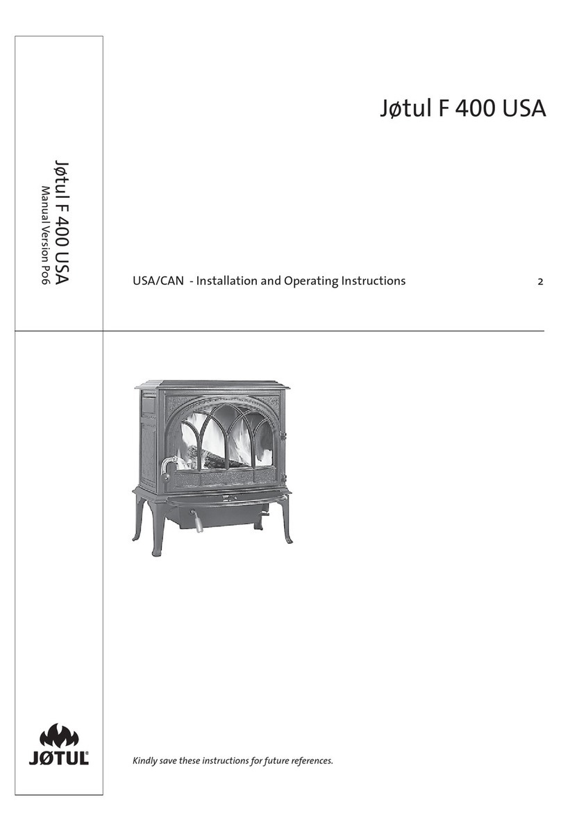
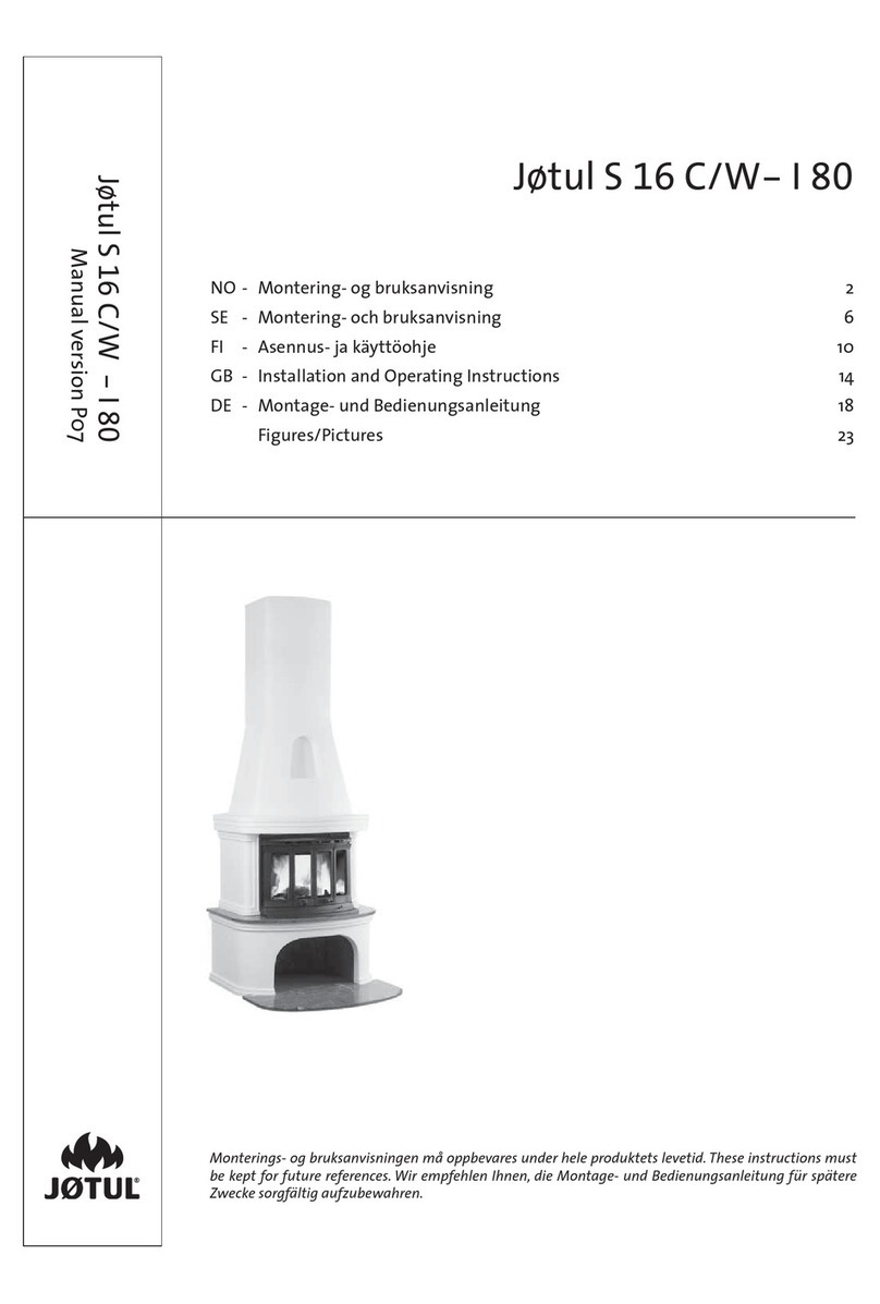
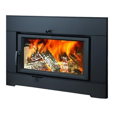
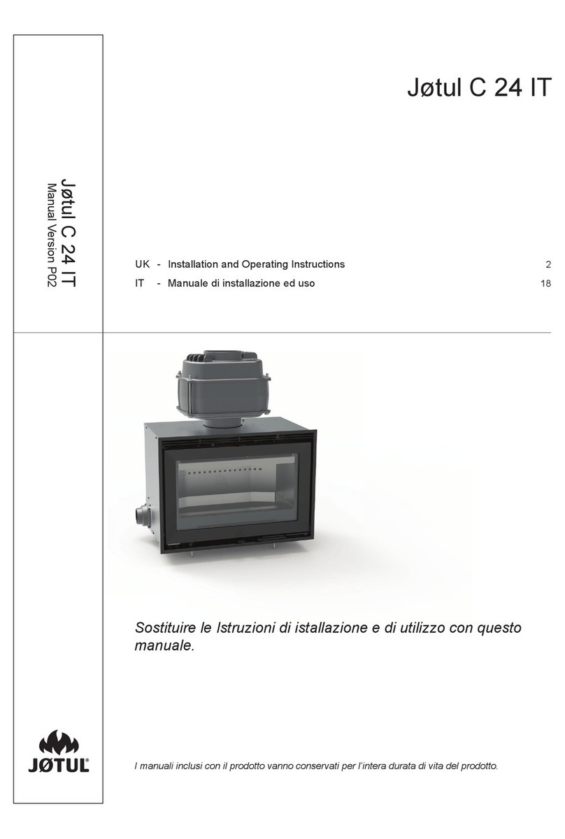
  9. Jøtul F 360 Series User manual

Jøtul F 360 Series User manual

Jøtul F 360
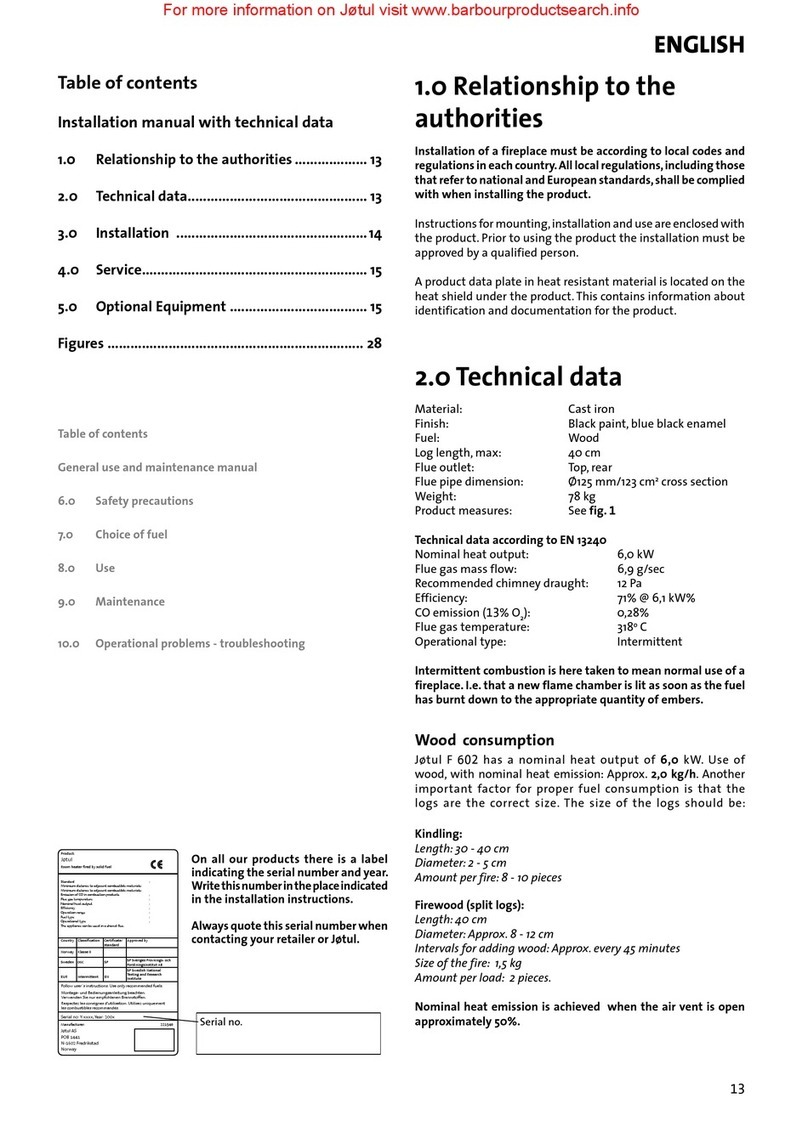
Konveksjonskappe / Convection Kit
Jøtul F 360 -series
Manual version P02
Förvara installationsmanualen på säker plats under produktens hela livslängd.These instructions must be
kept for future references.Wir empfehlen Ihnen, das Aufstellungshandbuch für spätere Zwecke sorgfältig
aufzubewahren. Ce document doit être conservé pendant toute la vie de l’appareil.
NO - Installasjonsmanual 3
DK - Installationsmanual 3
SE - Installationsmanual 4
FI - Asennusohjeet 4
GB - Installation Instructions 5
FR - Manuel d’ installation 5
ES - Instrucciones para instalación 6
IT - Manuale di installazione 6
DE - Montageanleitung 7
NL - Installatiehandleiding 7
Art.no. 51012290 / 51012291
2
3
NORSK
Montering av konveksjonssett
Viktig! Avstand til vegg av brennbart materiale, se fig 1.
NB! Godkjenningsskiltet som følger med, klistres på nederst på
baksiden av produktet (fig. 5).
• Løft av topplaten på produktet.
• Skru ut de to skruene (fig. 2 A) på hver side under produktet med
hjelp av en unbrakonøkkel som medfølger konveksjonssettet.
Montering ved topputtak for røykrør
Platefestene har to varianter.Øvre platefeste som skal monteres
på høyre side, er lik nedre platefeste som monteres på venstre
side av produktet. Øvre platefeste på venstre side er lik nedre
platefeste på høyre side.
1. Monter nedre platefeste (fig.3 A) på den ene siden ved å feste
med skruer M8x40 mm (fig. 3 B).
2. Monter deretter nedre platefeste på andre siden av
produktet.
3. Monter skjermplatene (fig.3 D) og de øvre platefestene (fig. 3 C)
på hver side.
4. Legg på topplaten (fig. 3 E) som medfølger konveksjonssettet.
5. Plasser toppristen (fig. 4) i topplaten.
DANSK
Montering af konvektionssæt
NB ! Afstand til væg af brændbart materiale - se fig. 1.
NB! Godkendelsesskiltet som følger med, limes nederst på
bagsiden af produktet (fig. 5).
• Løft toppladen af produktet.
• Skru de to skruer (fig. 2 A) på hver side under produktet
ud ved hjælp af en unbrakonøgle (leveres sammen med
konvektionssættet).
Montering ved topudtag for røgrør
Pladebeslagene har to varianter. Øverste pladebeslag, der skal
monteres på højre side, svarer til nederste pladebeslag, der
monteres på venstre side af produktet. Øverste pladebeslag på
venstre side svarer til nederste pladebeslag på højre side.
1. Montér nederste pladebeslag (fig.3 A) på den ene side ved at
fastgøre det med skruer M8x40 mm (fig. 3 B).
2. Montér derefter nederste pladebeslag på den anden side af
produktet.
3. Montér skærmpladerne (fig. 3 D) og de øverste pladebeslag (fig.
3 C) på hver side.
4. Læg toppladen på (fig. 3 E), der leveres sammen med
konvektionssættet.
5. Anbring topristen (fig. 4) i toppladen.
4
SUOMI
Konvektiopaneelien asennus
Huom! Etäisyys palavasta materiaalista valmistettuun seinään
(ks. kuva 1).
Huom.!Tulisijan mukana tuleva tyyppihyväksyntäkilpi liimataan
alas tulisijan taakse.
• Nosta pois tulisijan päällyslevy.
• Avaa tulisijan alla kummallakin puolella olevat kaksi
ruuvia (kuva 2 A) konvektiopaneelien mukana tulleella
ruuviavaimella.
Asennus, kun savuputki liitetään päältä
Kiinnikkeitä on kahdenlaisia. Oikean puolen yläkiinnike on
samanlainen kuin vasemman puolen alakiinnike, kun taas
vasemman puolen yläkiinnike on samanlainen kuin oikean
puolen alakiinnike.
1. Kiinnitä alakiinnike (kuva 3 A) toiselle sivulle M8x40 mm:n
ruuveilla (kuva 3 B).
2. Asenna sitten alakiinnike toiselle sivulle.
3. Kiinnitä suojalevyt (kuva 3 D) ja yläkiinnikkeet (kuva 3 C)
kummallekin puolelle.
4. Laita paikalleen konvektiopaneelien mukana tullut päällyslevy
(kuva 3 E).
5. Aseta yläritilä (kuva 4) päällyslevyyn.
SVENSKA
Montering av konvektionsset
OBS ! Avstånd till vägg av antändbart material – se bild 1
Godkännandeskylten som medföljer, ska klistras fast längst ned
på baksidan av produkten (bild 5).
1. Lyft av den övre plattan på produkten.
2. Lossa de två skruvarna på varje sida (bild 2 A) under produkten,med
sexkantnyckeln som medföljer konvektionssetet.
Montering vid uttag upptill för rökrör
Plattfästena är av två typer. Övre plattfäste som monteras på
höger sida = nedre plattfäste som monteras på vänster sida.
Övre plattfäste på vänster sida = nedre plattfäste på höger
sida.
1. Montera nedre plattfästet (bild 3 A) på ena sidan med
skruvar M8x40 (bild 3 B).
2. Montera sedan nedre plattfästet på andra sidan av
produkten.
3. Montera skärmplåtarna (bild 3 D) och de övre plattfästena
(bild 3 C) på varje sida.
4. Lägg på den övre plattan (bild 3 E) som medföljer
konvektionssetet.
5. Placera toppgallret (bild 4) i plattan.
5
ENGLISH
Fitting the convection kit
Note! Distance from the wall of flammable material – cf. fig. 1
Note! The accompanying approval label should be attached to
the rear of the product, at the bottom (fig. 5).
• Lift the top plate off the product.
• Remove the two screws (fig. 2 A) underneath the product on
either side, using the Allen key supplied with the convection
kit.
Installation using top outlet for flue pipe
The plate brackets come in two types. The upper plate bracket
that is fitted on the right side is the same as the lower plate
bracket that is fitted on the left side of the product. The upper
plate bracket on the left side is the same as the lower plate
bracket on the right side.
1. Fit the lower plate bracket (fig. 3 A) on one side by screwing
it on using M8x40 mm screws (fig. 3 B).
2. Then fit the lower plate bracket on the other side of the
product.
3. Mount the heat shield (fig. 3 D) and the upper plate brackets
(fig. 3 C) on each side.
4. Add the top plate (fig.3 E) which accompanies the convection kit.
5. Position the top grate (fig. 4) in the top plate.
FRANCAIS
Montage du kit de convection
N.B: Distance recommandée séparant le poêle d’un matériau
combustible (voir fig. 1)
N.B : Placer l’étiquette d’homologation fournie au dos du produit,
sur la partie inférieure.
• Soulever et dégager la plaque supérieure du produit.
• Déposer les deux vis (fig. 2 A) sous le produit,de chaque côté,
à l’aide de la clé hexagonale fournie avec le kit de convection.
Installation à l’aide de la sortie supérieure
pour le tuyau de fumée
Les supports de plaque sont disponibles selon deux modèles.
Le support de plaque supérieur monté sur le côté droit est le
meme que le support de plaque inférieur monté sur le côté
gauche du produit. Le support de plaque supérieur monté sur le
côté gauche est identique au support de plaque inférieur monté
sur le côté droit.
1. Monter le support de plaque inférieur (fig. 3 A) sur un côté à
l’aide des vis M8 x 40 mm (fig. 3 B).
2. Monter ensuite le support de plaque inférieur sur l’autre
côté du produit.
3. Monter l’écran thermique (fig. 3 D) et les supports de plaque
supérieurs (fig. 3 C) de chaque côté.
4. Ajouter la plaque supérieure (fig. 3 E) fournie avec le kit de
convection.
5. Positionner la grille supérieure (fig. 4) sur la plaque
supérieure.
6
ESPAÑOL
Montaje del kit de convección
Nota: Distancia a paredes de material combustible – vea la
figura 1
La etiqueta de autorización adjunta debe adherirse a la parte
trasera inferior del producto (fig. 5).
• Extraiga la placa superior del producto.
• Saque los dos tornillos (fig. 2 A) situados debajo, a ambos
lados del producto, con ayuda de la llave Allen suministrada
con el kit de convección.
Instalación con salida superior del tubo de
tiro
Se incluyen dos tipos de soportes de placa. El soporte de la placa
superior montado en el lado derecho es idéntico al soporte de la
placa inferior situado en el lado izquierdo del producto.El soporte
de la placa superior montado en el lado izquierdo es idéntico al
soporte de la placa inferior situado en el lado derecho.
1. Monte el soporte de placa inferior (fig. 3 A) en un lado con
ayuda de los tornillos M8x40 mm (fig. 3 B).
2. Seguidamente, monte el soporte de placa inferior en el otro
lado del producto.
3. Monte elescudo térmico(fig.3 D) y lossoportes deplacasuperior
(fig. 3 C) a cada lado.
4. Añada la placa superior (fig. 3 E) incluida en el kit de convección.
5. Sitúe la rejilla superior (fig. 4) en la placa superior.
ITALIANO
Montaggio del kit di convezione
Nota importante! Distanza da pareti di materiale infiammabile
– cf. Fig. 1
La targhetta acclusa, realizzata in materiale termoresistente,
contienedatieinformazionisull’identificazioneedocumentazione
del prodotto. Questa targhetta deve essere incollata in basso sul
lato posteriore del prodotto (fig. 5).
• Estrarre la piastra superiore del prodotto.
• Sul lato inferiore del prodotto, rimuovere le due viti (fig. 2 A)
in entrambi i lati, utilizzando la chiave Allen fornita con il kit
di convezione.
Installazione con lo scarico superiore per il
condotto
Le staffe per piastre fornite sono di due tipi. La staffa superiore,
da installare sul lato destro, corrisponde alla staffa inferiore, da
installare sul lato sinistro del prodotto.Allo stesso modo,la staffa
superiore destinata al lato sinistro corrisponde alla staffa inferiore
destinata al lato destro.
1. Posizionare una delle staffe inferiori (fig. 3 A) su un lato,
avvitandola mediante le viti M8x40 mm (fig. 3 B).
2. Montare quindi la seconda staffa inferiore sull'altro lato del
prodotto.
3. Installare lo scudo termico (fig. 3 D) e le staffe superiori (fig. 3 C)
su entrambi i lati.
4. Aggiungere la piastra superiore (fig. 3 E) fornita con il kit di
convezione.
5. Posizionare la grata superiore (fig. 4) nella piastra superiore.
7
NEDERLANDS
De convectieset plaatsen
N.B. De afstand tot de muur van brandbaar materiaal, conform
afb. 1
Let op! Het bijgesloten label met goedkeuringslabel moet aan
de achter-onderzijde van het products bevestigd worden (fig. 5).
• Til de bovenplaat van het product af.
• Verwijder de twee schroeven (fig.2 A) aan beide zijden onder
het product met de inbussleutel die bij de convectieset is
geleverd.
Installatie waarbij de bovenste uitlaat als
kachelpijp wordt gebruikt
Er zijn twee soorten plaatbeugels. De bovenste plaatbeugel
die aan de rechterzijde wordt gemonteerd is hetzelfde als de
onderste plaatbeugel die aan de linkerzijde van het product
wordt gemonteerd. De bovenste plaatbeugel aan de linkerzijde
is hetzelfde als de onderste plaatbeugel aan de rechterzijde.
1. Plaats de onderste plaatbeugel (fig. 3 A) aan één zijde door
deze vast te schroeven met M8x40 mm schroeven (fig. 3 B).
2. Plaats vervolgens de onderste plaatbeugel aan de andere
zijde van het product.
3. Monteer het hitteschild (fig. 3 D) en de bovenste plaatbeugels
(fig. 3 C) aan beide zijden.
4. Plaats de bovenplaat (fig. 3 E) van de convectieset.
5. Plaats het bovenrooster (fig. 4) in de bovenplaat.
DEUTSCH
Konvektionsset montieren
Hinweis! Nicht für Jøtul F 360 DE
Hinweis! Abstand zu einer Wand aus brennbaren Materialien
– siehe Abb. 1
Das beiliegende Zulassungsetikett ist unten an der Rückseite des
Produkts anzubringen.
• Heben Sie die Deckplatte vom Produkt ab.
• Lösen Sie die beiden Schrauben (Abb. 2 A) auf beiden Seiten
unter dem Produkt. Verwenden Sie dazu den Inbusschlüssel
im Lieferumfang des Konvektionssets.
Installation mit oberem Abzug für
Rauchgasrohr
Es existieren zwei Typen von Plattenhalterungen. Die obere
Plattenhalterung zur Anbringung auf der rechten Seite ist
identisch mit der unteren Plattenhalterung, die auf der linken
Seite des Produkts montiert wird.Die obere Plattenhalterung auf
der linken Seite ist identisch mit der unteren Plattenhalterung
auf der rechten Seite.
1. Bringen Sie die untere Plattenhalterung (Abb. 3 A) auf einer
Seite an, indem Sie sie mit M8x40 mm-Schrauben (Abb. 3 B)
befestigen.
2. Bringen Sie anschließend die untere Plattenhalterung auf der
anderen Seite des Produkts an.
3. Montieren Sie Hitzeschutzplatte (Abb. 3 D) und obere
Plattenhalterungen (Abb. 3 C) auf jeder Seite.
4. Bringen Sie die Deckplatte (Abb. 3 E) im Lieferumfang des
Konvektionssets an.
5. Setzen Sie den oberen Rost (Abb. 4) in die Deckplatte ein.
8
abcdefghi
300
200
150
925
805
735
720
591
521
509
418
368
400
400
400
552
571
571
347
357
357
621
630
630
100
100
100
CV modeller (produkt med konveksjonskappe
og halvisolert stålskorstein)
CV models (products with convection kit and
half insulated steel chimney) *
Basismodell med eller uten stålskorstein
Basic model w/half insulated steel chimney
Min. avstand til brennbar vegg ved ulike oppstillinger, fig. 1a
Min. distance to combustible wall by different configurations, fig. 1a
Mål/Measure
Oppstilling
Configuration
Jøtul F 360
Med dekorglass sider og halvisolert skorstein
With decor glass sides and
half insulated steel chimney
*Nicht für Jøtul F 360 DE
9
205
221
452
442
900092-P00
1025
740
1150
410
66
181
max 90°
Avstand til brennbar vegg med dreibar søyle. Se tabell ovenfor.
Distance to combustible wall with revolvable pedestal: See table above.
b
a
c
d
a
d
e
f
h
g
i
max 180°
d
a
h
e
Brennbar vegg
Combustibel wall
X
Y
Fig. 1
Min. avstand til brennbar vegg. Se tabell ovenfor.
Min. distance to combustible wall: See table above.
Jøtul F 361 / F 363 / F 364 / F 365 / F 366 / F 369
Produkt / Product:
Jøtul F361, F364, F365, F366, F369
Hull i gulv for uteluft
Hole in floor for external air supply
Ø 100 mm tilkobling/connection
Jøtul F363
Hull i gulv for uteluft
Hole in floor for external air supply
Ø 100 mm tilkobling/connection
Min. mål gulvplate
X/Y = I henhold til nasjonale
lover og regler.
Min. measure floorplate
X/Y = Acc. to national standards
and regulations.
10
Fig. 2
A
A
Fig. 3
c
c
D
D
A
A
B
B
E
Fig. 4 Fig. 5
les
c
ombustibles
r
e
c
ommandés.
R
espe
c
tez les
c
onsignes d'utilis
a
tion. Utilisez uniqueme
n
t
V
e
V
V
r
wenden Sie nur emp
f
ohlenen B
f
f
r
ennsto
f
f
f
f
en.
f
f
Mo
n
tage- und Bedienungsanleitung beac
h
ten.
F
ollow user`s instru
c
tions. Use only
r
e
c
ommended fuels.
standa
r
d
C
e
r
tific
a
te/
The appliance can be used in a sha
r
ed flu
e
.
Minimum distance
to adjace
n
t
c
ombustible m
a
terials:
Emission of
C
O in
c
ombustion p
r
odu
c
ts
Serial no
:
Y
-
xxxx
,
Y
ea
Y
Y
r
:
200x
Manu
f
a
f
f
c
tu
r
e
r
:
N-1602
F
r
edri
k
stad
No
r
wa
y
Jøtul AS
P
OB 1441
S
weden
E
U
R
I
n
termitte
n
t
Nominal he
a
t
outpu
t
No
r
wa
y
C
ou
n
t
r
y
r
Ope
r
a
tional
type
F
uel
type
Ope
r
a
tion
r
ange
E
f
ficiency
f
f
Klasse
I
I
Classific
a
tion
Standa
r
d
Flue gas
tempe
r
a
tu
r
e
R
oom he
a
ter fi
r
ed by solid fuel
P
r
odu
c
t:
Jøtul
SP
S
v
eriges P
r
o
vnings- och
xxxxxx
F
orskningsinstitu
rskningsinstitu
t
AB
SP
S
wedish N
a
tional
T
esting and
T
T
R
esea
r
ch
Institute
:
App
r
o
v
ed by
:
:
:
:
:
:
:
Minimum distance
to adjace
n
t
c
ombustible m
a
terials:
O
GC
SP
EN
les combustibles recommandés.
Respectez les consignes d'utilisation. Utilisez uniquement
Verwenden Sie nur empfohlenen Brennstoffen.
Montage- und Bedienungsanleitung beachten.
Follow user`s instructions. Use only recommended fuels.
standard
Certificate/
The appliance can be used in a shared flue.
Minimum distance to adjacent combustible materials:
Emission of CO in combustion products
Sweden
EUR
Nominal heat output
Norway
Country
Operational type
Fuel type
Operation range
Efficiency
Classification
Standard
Flue gas temperature
Room heater fired by solid fuel
Product:
Jøtul
:
Approved by
:
:
:
:
:
:
:
Minimum distance to adjacent combustible materials:
Original
E
F
F
U
oll
ol
R
l
l
11
Jøtul arbetar ständigt med att – om möjligt – förbättra sina produkter och vi reserverar oss
därför för ev. ändringar vad gäller tekniska data, färger och utrustning.
Jøtul bemüht sich ständig um die Verbesserung seiner Produkte, deshalb können
Spezifikationen, Farben und Zubehör von den Abbildungen und den Beschreibungen in der
Broschüre abweichen.
Jøtul pursue a policy of constant product development. Products supplied may therefore
differ in specification, colour and type of accessories from those illustrated and described in
the brochure.
Jøtul vise sans cesse à améliorer ses produits. C’est pourquoi, il se réserve le droit de modifier
les specifications, couleurs et équipements sans avis prélable.
Kvalitet
Jøtul AS har ett kvalitetssäkringssystem enligt NS-EN ISO 9001 för utveckling, produktion och
försäljning av kaminer. Denna kvalitetspolicy ska ge våra kunder den säkerhet och kvalitet som
Jøtul har stått för sedan företaget etablerades 1853.
Qualität
Jøtul AS hat ein Qualitätssicherungssystem,das sich bei Entwicklung,Produktion und Verkauf
von Öfen und Kaminen nach NS-EN ISO 9001 richtet.Diese Qualitätspolitik vermittelt unseren
Kunden ein Gefühl von Sicherheit und Qualität,für das Jøtul mit seiner langjährigen Erfahrung
seit der Firmengründung im Jahre 1853 steht.
Quality
Jøtul AS has a quality system that conforms to NS-EN ISO 9001 for product development,
manufacturing, and distribution of stoves and fireplaces. This policy gives our customers
quality and safety piece of mind as a result of Jøtul’s vast experience dating back to when the
company first started in 1853.
Qualité
Le système de contrôle de la qualité de Jøtul AS est conforme à la norme NS-EN ISO 9001 relative
à la conception, à la fabrication et à la distribution de poêles, foyers et inserts. Cette politique
nous permet d’offrir à nos clients une qualité et une sécurité reposant sur la vaste expérience
accumulée par Jøtul depuis sa création en 1853.
Jøtul AS
P.o. box 1411
N-1602 Fredrikstad
Norge
Art.nr 10026179-Po2
Jøtul AS, Oct. 2011

Other manuals for F 360 Series

1

This manual suits for next models

6

Other Jøtul Indoor Fireplace manuals

Jøtul F 166 C User manual

Jøtul

Jøtul F 166 C User manual

Jøtul F 373 ADVANCE User manual

Jøtul

Jøtul F 373 ADVANCE User manual

Jøtul GI 545 DV MV User manual

Jøtul

Jøtul GI 545 DV MV User manual

Jøtul F 602 ECO User manual

Jøtul

Jøtul F 602 ECO User manual

Jøtul GI 350 DV User manual

Jøtul

Jøtul GI 350 DV User manual

Jøtul S 43 C User manual

Jøtul

Jøtul S 43 C User manual

Jøtul F 3 C User manual

Jøtul

Jøtul F 3 C User manual

Jøtul C 350 User manual

Jøtul

Jøtul C 350 User manual

Jøtul I 350 FL User manual

Jøtul

Jøtul I 350 FL User manual

Jøtul F 145 User manual

Jøtul

Jøtul F 145 User manual

Jøtul FS 175- I 520 User manual

Jøtul

Jøtul FS 175- I 520 User manual

Jøtul F 118 CB User manual

Jøtul

Jøtul F 118 CB User manual

Jøtul FS 73 User manual

Jøtul

Jøtul FS 73 User manual

Jøtul C 24 User manual

Jøtul

Jøtul C 24 User manual

Jøtul Terrazza User manual

Jøtul

Jøtul Terrazza User manual

Jøtul F 360 Series User manual

Jøtul

Jøtul F 360 Series User manual

Jøtul I 520 F User manual

Jøtul

Jøtul I 520 F User manual

Jøtul F 305 B Manual

Jøtul

Jøtul F 305 B Manual

Jøtul F 305 Series User manual

Jøtul

Jøtul F 305 Series User manual

Jøtul I 570 FL Instruction manual

Jøtul

Jøtul I 570 FL Instruction manual

Jøtul F 470 SHD Series User manual

Jøtul

Jøtul F 470 SHD Series User manual

Jøtul F 376 HT DE User manual

Jøtul

Jøtul F 376 HT DE User manual

Jøtul Cube 200 GG WS Manual

Jøtul

Jøtul Cube 200 GG WS Manual

Jøtul F 200 User manual

Jøtul

Jøtul F 200 User manual

Popular Indoor Fireplace manuals by other brands

safretti Magic-Fire MISTERO 500 user manual

safretti

safretti Magic-Fire MISTERO 500 user manual

Hanover CAM14FSFP-1BLK instructions

Hanover

Hanover CAM14FSFP-1BLK instructions

Sirocco Eco3 Installation and user instructions

Sirocco

Sirocco Eco3 Installation and user instructions

STUFA REBECCA Instructions for use and maintenance

STUFA

STUFA REBECCA Instructions for use and maintenance

RD WORKS FP201R owner's manual

RD WORKS

RD WORKS FP201R owner's manual

Ezee Glow Mini Zara owner's manual

Ezee Glow

Ezee Glow Mini Zara owner's manual

Vermont Castings Intrepid II 1308 owner's guide

Vermont Castings

Vermont Castings Intrepid II 1308 owner's guide

Bayside Furnishings EF22-33B operating manual

Bayside Furnishings

Bayside Furnishings EF22-33B operating manual

Escea EF5000 installation guide

Escea

Escea EF5000 installation guide

ESA M36E OWNER'S OPERATION AND INSTALLATION MANUAL

ESA

ESA M36E OWNER'S OPERATION AND INSTALLATION MANUAL

Sylvania SGQC113-MBK instruction manual

Sylvania

Sylvania SGQC113-MBK instruction manual

Lennox Hearth Products Performer C210 Installation and operation manual

Lennox Hearth Products

Lennox Hearth Products Performer C210 Installation and operation manual

AMBIONAIR FLAME EF628 Installation and user instructions

AMBIONAIR FLAME

AMBIONAIR FLAME EF628 Installation and user instructions

Stuv 21/65H installation instructions

Stuv

Stuv 21/65H installation instructions

Superior GI-3821N installation instructions

Superior

Superior GI-3821N installation instructions

Ameriwood HOME AltraFlame 2303096COM manual

Ameriwood HOME

Ameriwood HOME AltraFlame 2303096COM manual

Desa Comfort Glow CF26PTA OWNER'S OPERATION AND INSTALLATION MANUAL

Desa

Desa Comfort Glow CF26PTA OWNER'S OPERATION AND INSTALLATION MANUAL

Dimplex BLF74 Servise manual

Dimplex

Dimplex BLF74 Servise manual

manuals.online logo
manuals.online logoBrands
  • About & Mission
  • Contact us
  • Privacy Policy
  • Terms and Conditions

Copyright 2025 Manuals.Online. All Rights Reserved.