J2 580 User guide

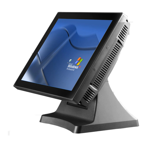
J2 580 Integrated Touchscreen Computer
System Manual
May 2008

580 System Manual
Version 1.0 May 31, 2008
2
Contents
Overview............................................................................................................................ 3
Specification....................................................................................................................... 4
Packing List....................................................................................................................... 6
Standard Items ................................................................................................................ 6
System View....................................................................................................................... 7
Front View...................................................................................................................... 7
Rear View ....................................................................................................................... 7
I/O View.......................................................................................................................... 8
Optional Items................................................................................................................... 9
System Installation.......................................................................................................... 10
Counter Top Base ......................................................................................................... 10
VESA / Wall Mount Bracket Installation..................................................................... 12
MSR Installation........................................................................................................... 13
Hard Drive Access........................................................................................................ 14
Replacing the Mother Board......................................................................................... 15
Adding / Upgrading SDRAM....................................................................................... 16
Removing the Power Supply Adaptor .......................................................................... 16
Jumper Settings............................................................................................................... 17
580 Motherboard........................................................................................................... 17
Cash Drawer.................................................................................................................. 24
BIOS Settings .................................................................................................................. 27
Starting the BIOS Setup................................................................................................ 27
When a Problem Occurs ............................................................................................... 27
BIOS Menus.................................................................................................................. 27
Driver Installation........................................................................................................... 29
Driver Download .......................................................................................................... 29
Chipset Driver Installation............................................................................................ 29
VGA Driver Installation ............................................................................................... 31
POSTouch Driver Installation....................................................................................... 32
10/100Mb LAN Driver Installation.............................................................................. 35
Additional Drivers/Utilities .......................................................................................... 35
Customer Display Option............................................................................................... 36
Dip Switch and Software Setting.................................................................................. 37

580 System Manual
Version 1.0 May 31, 2008
3
Overview
The J2 580 is unique in design. Building on the J2 values and innovative design practices
of the past J2 have produced a product that will not only meet the requirements of
retailers today, but future proof their investment for many years to come.
The 580 Integrated Touch screen computer is an “all in the head” design that fills the
role of a counter top or wall/pole mounted computer in the same unit. Both the counter
top base and VESA/ wall mount brackets come standard with the 580.
There are 3 main variants of this model available, a 1.0GHz Celeron M, 1.5GHz Celeron
M and 1.8 GHz Pentium M versions. Utilizing the latest technology from Intel the 580
has an entry level specification adopting a fan-less approach progressing to the high
specification Intel processors that accommodate power hungry applications. Accessibility
is the key to machine maintenance or upgradeability. The motherboard can be easily
removed and exchanged, upgrades to the memory modules can be easily undertaken as
the tray housing the technology slides in and out with the greatest of ease. A complete
motherboard upgrade can be carried out in less than 10 seconds! The HDD is easily
accessible as it too is housed on a removable tray. The footprint of the J2 580 is
particularly compact making it ideal for the space conscious retailer.
The 580 thick or thin configurations support the standard Microsoft operating systems
XP, WePOS, CE.NET and XPe, further demonstrating its versatility. The 580 is equally
proficient with the many flavors of Linux.

580 System Manual
Version 1.0 May 31, 2008
4
Specification
Main board
CPU Support Intel Celeron M ULV 1GHz FSB 400Mhz fan-less
Intel Celeron M 1.5G / Pentium M 1.8G FSB 400Mhz
Chipset Intel 852GM + ICH4 FSB 400Mhz
System Memory 2 x DDR DIMM socket up to 2 GB FSB200/266Mhz
Graphic
Memory Share system memory up to 64MB
BIOS AWARD PnP
LCD Touch Panel
LCD Size 15” TFT LCD
Brightness 250nits
Maximal
Resolution 1024 x 768
Touch Screen Resistive 5 wire
Tile Angle 0゜~ 90゜
Storage
HDD one slim HDD bay (SATA interface) Quick Change
Flash Memory CF adapter for HDD slot Quick Change
Expansion
Mini-PCI Slot 1, normally used for 802.11g wireless card
I/O Ports
Rear I/O
USB 4 x in cable well / 1 x on left side
Serial / COM 4 x RJ 45 COM ( COM 3 /COM 4 pin 9 with 5V/12V by jumper )
Parallel 1, DB25 in cable well
LAN (10 / 100) 1, RJ45 in cable well (Realtek RTL8139)
2n
d
VGA 1 supports standard VGA monitor or optional 12” or 10.4” secondary
customer side display, powered from 580
Cash Drawer 1 x RJ 11 (24V or 12V) with status
DC Jack 1 Power in, 19VDC 4.75 amps
Audio Jack 1 x Line-out, 1 x Line-in in cable well
Font I/O Indicator
Power LED 1, Green for system power on

580 System Manual
Version 1.0 May 31, 2008
5
Power
Power Adapter 19VDC, 90W, 100-240 VAC, 1.5A MAX
Optional Peripheral
Input Device
MSR 3 Track ( on PS2 port, wedge type )
I-button Dallas Key I-button ( on PS2 port, wedge type )
2-in-1 MSR MSR 3 track (PS2) / Finger Print (USB)
Output Device
Second
Display optional 12.1" or 10.4” 2nd display, with or without touch
Customer
Display Customer Side VFD display with 2 x20 characters
UPS battery 2 hour DC UPS, Mounts in base of unit
Mounting
Standard Counter Top Base, Adjustable Viewing Angle 0-90°
Included Wall Mount / VESA Mount Bracket
Optional Optional adjustable angle VESA/Wall mount bracket
Environment
EMC & Safety FCC, Class A, CE, LVD
Operating
Temperature 5 ~ 40℃
Storage
Temperature -20 ~ 55℃
Operating
Humidity 20% ~ 80% RH non condensing
Storage
Humidity 20% ~ 85% RH non condensing
Dimensions
(W x D x H) 370x250x340mm
Weight 7.45kg
OS Support Windows XP, WEPOS, XP Embedded, Windows CE 5.0, Linux
* This specification is subject to change without prior notice.

580 System Manual
Version 1.0 May 31, 2008
6
Packing List
Take the system unit out of the carton. Remove the unit from the carton by holding it by
the foam inserts. The following contents should be found in the carton:
Standard Items
1: System 2: COM Cables (3)
3: Printer Cables
4: Wall mount / VESA adapter
Not pictured
5: Screws for VESA Mount (4)
6: COM port cable labels

580 System Manual
Version 1.0 May 31, 2008
7
System View
Front View
Rear View
Card reader
Ventilation
I/O Ports
LED
HDD
Module USB
OFF/ON BUTTON

580 System Manual
Version 1.0 May 31, 2008
8
I/O View
DC-IN
LAN
Line out Line in
Parallel USB Cash Drawer
COM 1, 2, 3, 4
VGA
OFF/ON BUTTON

580 System Manual
Version 1.0 May 31, 2008
9
Optional Items
Power Supply Bracket Hinge bracket
MSR module (front swipe) iButton / iButton-MSR combo
Finger Print / MSR-Finger Print Combo Secondary Display 12” (also 10.4” available)
2X20 Character Customer Display

580 System Manual
Version 1.0 May 31, 2008
10
System Installation
Counter Top Base
The 580 is shipped with a counter top base. This base allow for the head to be adjust from
0-90°.
To remove the integrated head from the base loosen the thumbscrew located on the back
of the unit under the hinge of the counter top base as shown below. Then lift the head as
shown.
a. Loosen the thumbscrew (1)
b. Lift the panel up and separate it from the stand bracket

580 System Manual
Version 1.0 May 31, 2008
11
To mount the 580 to the base do the reverse as shown below.
a. attach the panel to the desk mount hinge bracket and slide it into the position as
shown by the arrows
b. Tighten the thumbscrew to finish the installation

580 System Manual
Version 1.0 May 31, 2008
12
VESA / Wall Mount Bracket Installation
The VESA / Wall mount bracket as threaded mounting holes (screws provided) for the
75mm VESA standard and unthreaded holes for the 100mm standard.
Using the 100mm hole pattern the bracket can be used, by itself, as a wall mount bracket.
After install thumbscrew clip mount the bracket to the wall then hang the 580 on the
bracket.
Install screw to secure thumbscrew clip
The bracket slides on to the 580 mount posts as shown. Normally the bracket would
already be mounted to the wall or a VESA mount and the 580 would be hung on the
bracket. Once in place the thumbscrew would be tightened.

580 System Manual
Version 1.0 May 31, 2008
13
MSR Installation
a. Remove the screws (2) b. Connect the cable and tighten the screw
c. Slide the MSR into the position and tighten the screw to finish the installation. Be
careful not to pitch the cable when installing.

580 System Manual
Version 1.0 May 31, 2008
14
Hard Drive Access
Loosen the screw
Slide the Hard Module as shown

580 System Manual
Version 1.0 May 31, 2008
15
Replacing the Mother Board
Loosen the two thumbscrews (you may require a screw driver)
Pull the handle in the direction as shown order to release the mainboard tray from the system

580 System Manual
Version 1.0 May 31, 2008
16
Adding / Upgrading SDRAM
Use your finger to push the DIMM slot ejector clips into the down position.
Remove the SDRAM from the slot in the direction as shown by the arrow to replace it
Note: There are two memory socket, one one each side of the mother board. Population order does
not matter.
Removing the Power Supply Adaptor
Remove the two screws to release the adaptor and the bracket from the system.

580 System Manual
Version 1.0 May 31, 2008
17
Jumper Settings
580 Motherboard

580 System Manual
Version 1.0 May 31, 2008
18
Connectors
Connector Function Connector Function
CN1 Audio Line Out IDE1 Primary IDE Connector
CN2 Audio Line In PRN1 Parallel Port
CN13 COM5 for Touch PWR1 +19V Power Adapter
CN15 CPU FAN Connector RJ11_1 Cash Drawer Connector
CN16 Hardware Reset RJ45_1 LAN (On Board)
CN18 USB2 RJ45_2 COM1, COM2, COM3,
COM4
CN19 LCD Interface Connector USB1 USB3, USB4
CN20 Inverter Connector USB2 USB5, USB6
CN21 Card Reader Connector SW1 Power Switch
Jumper Settings
CMOS Operation Mode
Function JP8
CMOS Normal ◎N/C
CMOS Reset 1-2
To clear the CMOS:
Unplug DC power from the unit.
Remove the mother board.
Change the JP8 jumper setting from N/C to 1-2.
Wait 2 seconds.
Change the JP8 jumper setting back to N/C.
Reinstall mother board.
Apply power and continue.
Power Mode Setting
Function JP6
ATX Power ◎N/C (use for 580)
AT Power 1-2

580 System Manual
Version 1.0 May 31, 2008
19
Cash Drawer Power Setting
Voltage JP4
+12V ◎1-2
N/A 3-4
+24V 5-6 (default)
COM3 & COM 4 Power Setting
Function JP3
COM3 PIN10_RI ◎1-2
COM3 PIN10_+5V 3-4
COM3 PIN10_+12V 5-6
COM4 PIN10_RI ◎7-8
COM4 PIN10_+5V 9-10
COM4 PIN10_+12V 11-12
Card Reader Setting
Function JP11
◎Docking 1-2
On Board 3-4
LCD ID Setting
Panel
Number Resolution LVDS JP7
Bits Channel 1-2 3-4 5-6 7-8
0 640 x 480 18 Single SHORT SHORT SHORT SHORT
1 800 x 600 18 Single SHORT SHORT SHORT OPEN
2 * 1024 x 768 18 Single SHORT SHORT OPEN SHORT
3 1280 x 1024 24 Dual SHORT SHORT OPEN OPEN
4 1024 x 768 24 Single SHORT OPEN SHORT SHORT
5 800 x 600 24 Single SHORT OPEN SHORT OPEN
* This is the setting required for the 580 system

580 System Manual
Version 1.0 May 31, 2008
20
COM2 RS232
Function JP9 JP10
◎RS232 1-2
3-4
5-7
1-2
Note:
OPEN
SHORT
Connectors Pin Definition
CN4: Speaker & MIC Connector
Pin 1 AMP_ORL Pin 2 GND
Pin 3 GND Pin 4 AMP_ORR
Pin 5 GND Pin 6 MIC1
CN9: CD-IN Connector
Pin 1 CDIN_L Pin 2 CDIN_REF
Pin 3 CDIN_R Pin 4 CDIN_REF
CN11: Power Connector For 3.5” HDD
Pin 1 +12V Pin 2 GND
Pin 3 GND Pin 4 +5V
CN13: COM5
Pin 1 DCD# Pin 2 RX#
Pin 3 TX# Pin 4 DTR#
Pin 5 GND Pin 6 DSR#
Pin 7 RTS# Pin 8 CTS#
Pin 9 RI Pin 10 +5V
CN15: CPU FAN Connector
Pin 1 +5V Pin 2 Feedback
Pin 3 GND
CN18: USB 2
Pin 1 +5V_USB1 Pin 2 USB20_R_P1
Table of contents
Other J2 Touchscreen manuals
Popular Touchscreen manuals by other brands

Johnson Controls
Johnson Controls Tyco HC2TCHPRO user manual

Honeywell Home
Honeywell Home PROWLTOUCH Quick installation guide

Elo TouchSystems
Elo TouchSystems 3200L user manual

Wacom
Wacom CINTIQ DTK-2700 Important product information

Touch Dynamic
Touch Dynamic EC150 user manual

MISURA
MISURA M16TB user manual