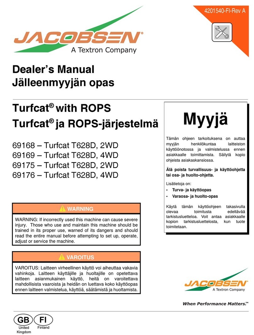
Jacobsen 600 Series User manual
Other Jacobsen Lawn And Garden Equipment manuals
Jacobsen
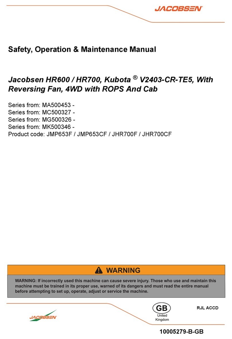
Jacobsen JMP653F User manual
Jacobsen
Jacobsen 88006 Sand Scorpion User manual
Jacobsen
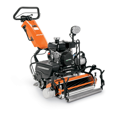
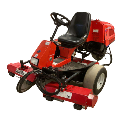
Jacobsen Eclipse 2 User manual
Jacobsen
Jacobsen Greens King VI Guide
Jacobsen
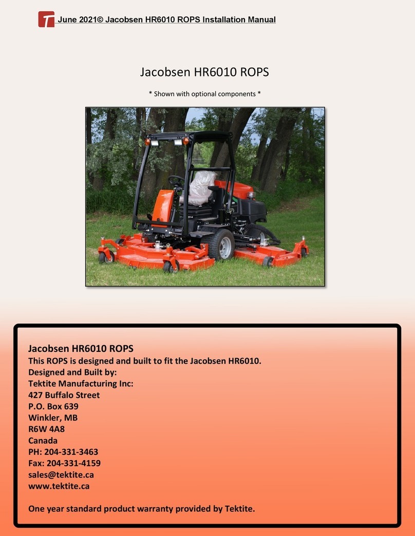
Jacobsen HR6010 ROPS User manual
Jacobsen
Jacobsen GreensAire 24 58234 User manual
Jacobsen
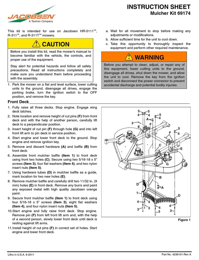
Jacobsen 69174 User manual
Jacobsen
Jacobsen GreensAire 24 58233 User manual
Jacobsen
Jacobsen GA580 User manual
Jacobsen
Jacobsen RYAN 544844D Guide
Popular Lawn And Garden Equipment manuals by other brands

Vertex
Vertex 1/3 HP Maintenance instructions

GHE
GHE AeroFlo 80 manual

Millcreek
Millcreek 406 Operator's manual

Land Pride
Land Pride Post Hole Diggers HD25 Operator's manual

Yazoo/Kees
Yazoo/Kees Z9 Commercial Collection System Z9A Operator's & parts manual

Premier designs
Premier designs WindGarden 26829 Assembly instructions

AQUA FLOW
AQUA FLOW PNRAD instructions

Tru-Turf
Tru-Turf RB48-11A Golf Green Roller Original instruction manual

BIOGROD
BIOGROD 730710 user manual

Land Pride
Land Pride RCF2784 Operator's manual

Makita
Makita UM110D instruction manual

BOERBOEL
BOERBOEL Standard Floating Bar Gravity Latch installation instructions

