Jadak PHOTO RESEARCH TRU 8 User manual

TRU 8 / VideoWin 3 Quick Reference Guide
Page 1of 9
7279 William Barry Blvd, NY 13212-3349 USA•TEL 315-701-0678
Introduction
This is intended as a quick reference guide and does not provide complete operational
instructions for the TRU 8 or VideoWin 3. Consult the VideoWin 3 Instruction Manual for
full details.
1. Unpack the instrument.
2. Inspect for physical damage.
3. The TRU 8 Imager is delivered with the objective lens (MS-60) attached to the instrument
and lens cap installed on the end of the lens.
4. Remove the lens cap by holding firmly and pulling away from the instrument. Do not twist
the lens cap to remove it.
Step 1 Step 2
WARNING: DO NOT REMOVE ANY FILTERS INSTALLED ON THE OBJECTIVE LENS.

TRU 8 / VideoWin 3 Quick Reference Guide
Page 2of 9
5. Check to see that the front filter is clean and free of dirt and finger prints before making
measurements with the TRU 8.
6. Connect the TRU 8 to a suitable AC power source by:
a. Gently inserting the connector into the TRU 8 power supply until it comes to a stop
and then screwing on the connector collar by turning clockwise until finger tight.
DO NOT OVERTIGHTEN.
b. Insert the AC power cord connector into the Adaptor and the AC plug into a
compatible 100 –240 volt AC outlet.
Step 4
Connect the TRU 8 to the PC controller using the supplied USB TYPE B connector from the
TYPE B port on the TRU 8 to an available USB port on the PC. Once the instrument is
connected to the PC via the USB cable, Windows will display the following dialog confirming it
recognizes that the flash drive is available. In the following example, the drive inside the TRU8
has been assigned to the D: drive.
7. Install VideoWin software by launching VideoWin 3.x.xx.x.msi (x.xx.x is the VideoWin 3
version) located in the flash drive of the TRU8.

TRU 8 / VideoWin 3 Quick Reference Guide
Page 3of 9
Calibration File Installation
Calibration files are located on the flash drive inside the TRU8. Once the instrument is
connected to the PC via the USB cable, Windows will display the following dialog confirming it
recognizes that the flash drive is available. In the following example, the drive inside the TRU8
has been assigned to the D: drive.
Figure 1 - TRU8 Internal Drive Assignment
To copy the calibration files to your hard disk after launching VideoWin:
Calibration files must be copied prior to using the TRU-IMAGE
TRU8.
!
Note

TRU 8 / VideoWin 3 Quick Reference Guide
Page 4of 9
1. Launch VideoWin.
2. Click on Tools →Device Manager.
3. Make sure that all instruments are disconnected. If an instrument is connected, it can be
disconnected by highlighting the instrument, and clicking on Disconnect.
Figure 2 –Disconnecting an instrument
1. Click on Tools →Device Manager →Options.--> Copy Calibration Files.

TRU 8 / VideoWin 3 Quick Reference Guide
Page 5of 9
2. Navigate to the drive designated to the TRU8 flash drive. In the previous example, Drive
D:.

TRU 8 / VideoWin 3 Quick Reference Guide
Page 6of 9
3. Click on OK. The copy process begins automatically and a status indicator reports the
progress.
4. At the completion of the copy process, the TRU8 is ready for use.
Or the manually copy the calibration files:
1. Make sure the VideoWin is not running.

TRU 8 / VideoWin 3 Quick Reference Guide
Page 7of 9
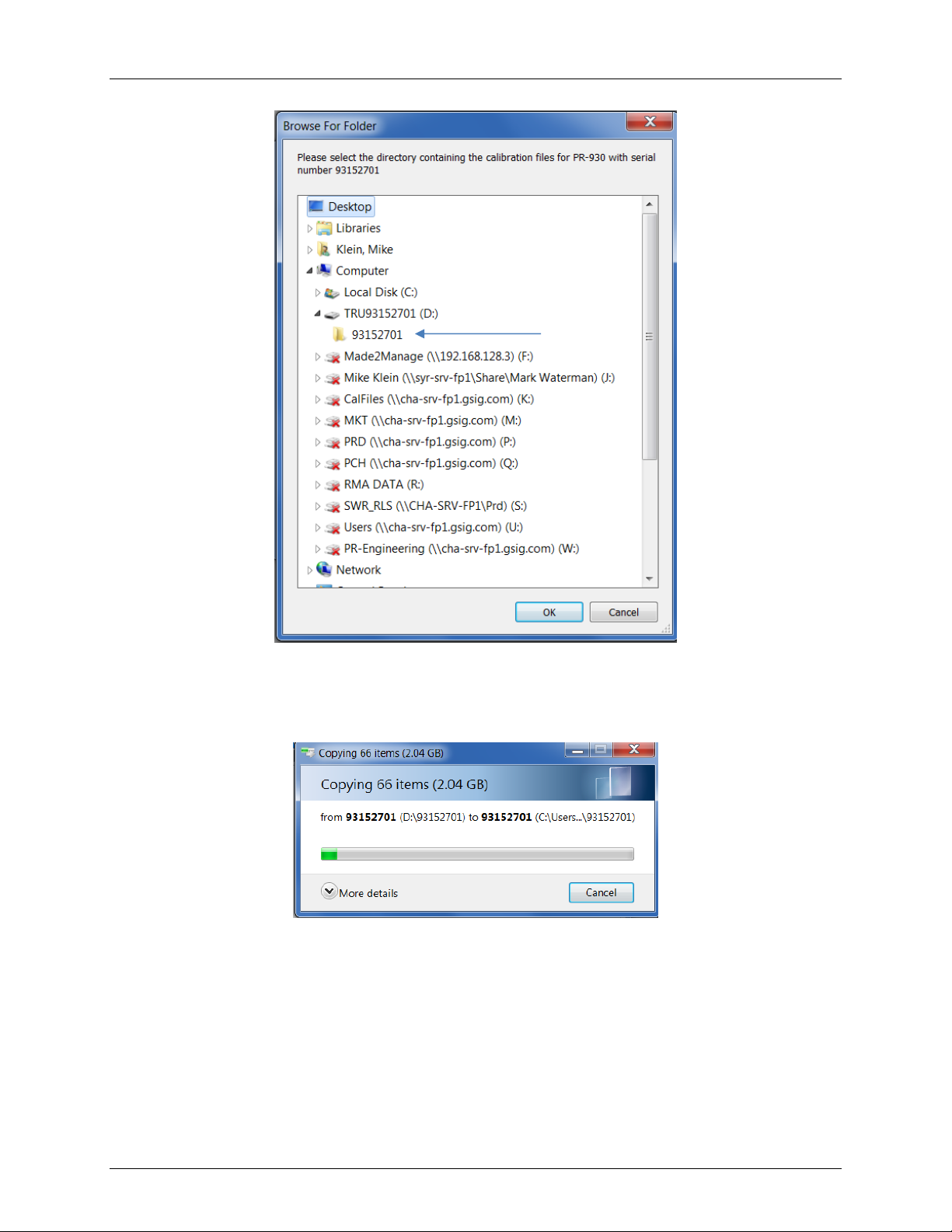
2. Using Windows Explorer, copy the calibration file folder on the flash drive in the TRU8
folder (see above) above to the following location on your hard disk.
C:\Users\Public\VideoWin
Instrument Verification
Perform this test if unexpected uncertainties are experienced when measuring the device under
test (DUT).
Physical Set Up Requirements
Required Equipment
•LRS-4545-6 Calibrated variable luminance and chromaticity standard or equivalent
(Reference Source).
•DUT
•Calibrated spectroradiometer capable of reporting luminance and CIE chromaticity
values with a measuring aperture subtending 2° or smaller.
Minimum Computer Requirements
•Windows based PC
•8 GBytes RAM –more is recommended especially if multiples apps are open
simultaneously
•64 bit Windows 7 or higher
•One available USB 2.0 or higher interface
•Pointing device (mouse)
•CD/DVD player for VideoWin software / calibration files installation
The International Measurements Display Standard (IDMS) should be used as the basis for any
display measurement task. This specification is available from the Society for Information
Display Web site. A brief summary of best practices from the standard are given as follows:
1. Physical distance of LMD (light measurement device) should be no less than 500mm
2. The angular cone of acceptance of the LMD should not exceed 2 degrees.
3. The angular field of view should not exceed 2 degrees.
4. The minimum number of pixels should be no less than 500 pixels or a measurement diameter
greater than 26 pixels for a circular measurement area.
5. Darkroom measurement conditions should be less than 0.01 lux with no obvious reflections or
veiling glare component in the field of measurement.
6. Warm up time should be the greater of 20 minutes or time to reach a fixed measurement of
luminance less than 1%.
7. The following environmental conditions must be obtained:
a. 24°C ±5°C
b. 84 kPa to 106 kPa
c. (25 in Hg –31 in Hg). These are the air pressures for approximately1609 m [5280 ft or
1 mile] down to a little below sea level, for sea level: 101 325 Pa, 76 mm Hg, 29.92 in Hg.
d. 25 % to 85 % RH (non condensing)

TRU 8 / VideoWin 3 Quick Reference Guide
Page 8of 9
In some instances, particularly with very small, high resolution portable displays, the 500mm distance
may be problematic. The goal should be to maintain the 2 degree angular cone of acceptance, if
possible. The standard explicitly states that any deviation from the 500mm measurement distance should
be noted.
Figure 3 Description of various terms from the standard
Confirming the general calibration accuracy of the Imager
Procedure
1. Confirm that ambient temperature and humidity requirements are met
2. Power and warm-up the Reference Source and all instruments for at least 20
minutes
3. Adjust the reference source for correct lamp current and luminance
4. Align and focus the TRU8 on the measuring window of the Reference Source. Make
sure the distance from the front of the lens to the target is a minimum of 10 focal
lengths of the objective lens. For example, the focal length of the MS-60 objective
lens is 60 mm, therefore the recommended distance is 600 mm (1.97 ft.).
5. Measure the Reference Source with the TRU8.
6. In VideoWin software, generate an AOR centered on the measuring window with a
size of at least 330 x 247 camera pixels (1% of total camera pixels).
7. If the measured results do not agree with the published data for the Reference
Source, measure the Reference Source with the spectroradiometer taking care to
match the area sampled by the measuring aperture of the spectroradiometer to that
of the AOR generated in Step 6.
8. If the TRU8 and spectroradiometer agree with each other but do not agree with the
standard, then the issue lies with the standard.
9. If one of the instruments agrees with the standard and the other does not, then the
instrument that disagrees requires calibration.

TRU 8 / VideoWin 3 Quick Reference Guide
Page 9of 9
Confirming the accuracy of the Imager for measuring the DUT
Procedure
1. Make sure that the TRU8, spectroradiometer and DUT have been warmed up for at
least 20 minutes.
2. Align and focus the TRU8 on the DUT. Make sure the distance from the front of the
lens to the target is a minimum of 10 focal lengths of the objective lens. For
example, the focal length of the MS-60 objective is 60 mm, therefore the
recommended distance is 600 mm (1.97 ft.).
3. Measure the DUT with the TRU8.
4. In VideoWin software, generate an AOR with a size of at least 330 x 247 camera
pixels (1% of total camera pixels). If measuring characters on a device, the best
results are obtained when the AOR is smaller than the illuminated portion of the
character (e.g. character stroke). If measuring a flat field image on devices such as
an LCD or OLED, follow the suggestion of the IDMS above for the correct measuring
area of the DUT.
5. Align and focus the spectroradiometer on the DUT. Make sure that the measuring
aperture covers the same area as the AOR created in Step 4.
6. When measuring the DUT, the spectroradiometer is the reference instrument. If the
TRU8 does not agree with the spectroradiometer, it will be necessary to generate
calibration factors either through the Matrix Calibration function (for adjustable DUT’s
such as LCD’s and OLED’s) or single color calibration factors using the Color
Correction feature of VideoWin.
7. Consult the VideoWin 3 Instruction Manual for detailed information regarding the
Matrix Generator and Color Correction Factor features.
Matrix Generator Color Correction Factors
This manual suits for next models
1
Table of contents
Other Jadak Barcode Reader manuals
Popular Barcode Reader manuals by other brands

HDWR
HDWR HD-SL99 instructions

Datalogic
Datalogic Quickscan I Quick reference guide

Motorola
Motorola LS4208 - Symbol - Wired Handheld Barcode... Product reference guide

RIOTEC
RIOTEC CR6307A Programming Quick Guide

Hand Held Products
Hand Held Products HANDHELD 3800G user guide

Nisuta
Nisuta NSLC021 user manual