jakob OTT HSK Series User manual

Product Information
OTT-JAKOB GmbH & Co. +49 (0) 83 64 / 98 21 -0
Spanntechnik KG ¬+49 (0) 83 64 / 98 21 -10
D - 87663 Lengenwang |http://www.ott-jakob.de
95.600.019.D.E / 2006-03
HSK-Clamping-Units
95.600.019.D.E

Product Information
Table of contents
1 Product Description.......................................................................................................4
1.1 Standard..........................................................................................................................4
1.2 Medium transfer...............................................................................................................5
1.3 Ceiling speed...................................................................................................................6
1.4 Transferable torque.........................................................................................................6
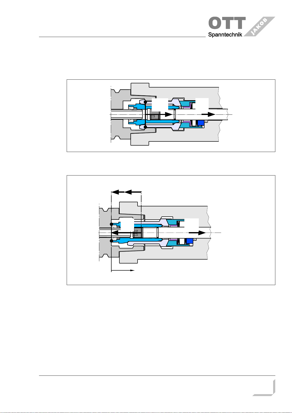
1.5 Forces at the HSK-clamping unit.....................................................................................7
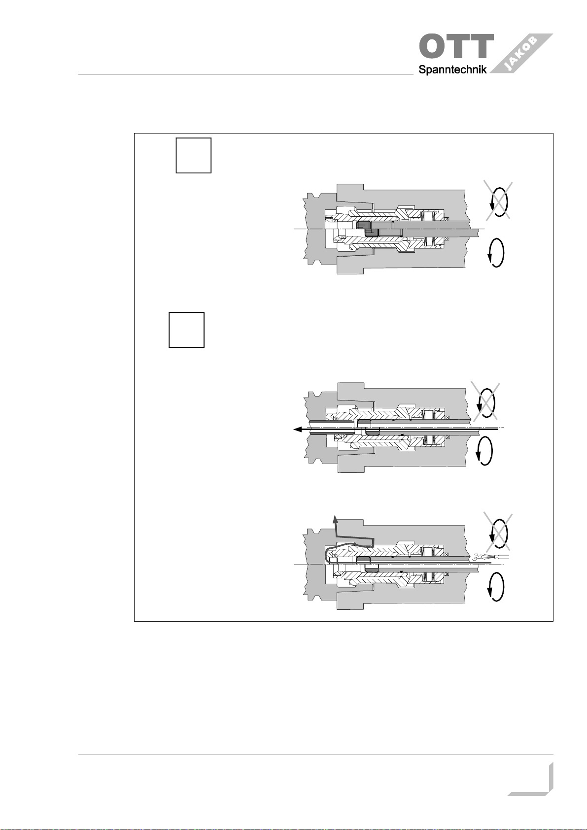
1.5.1 Clamped position.............................................................................................................7
1.5.2 Unclamped position.........................................................................................................7
1.5.3 Diagram...........................................................................................................................8
1.5.4 Table................................................................................................................................8
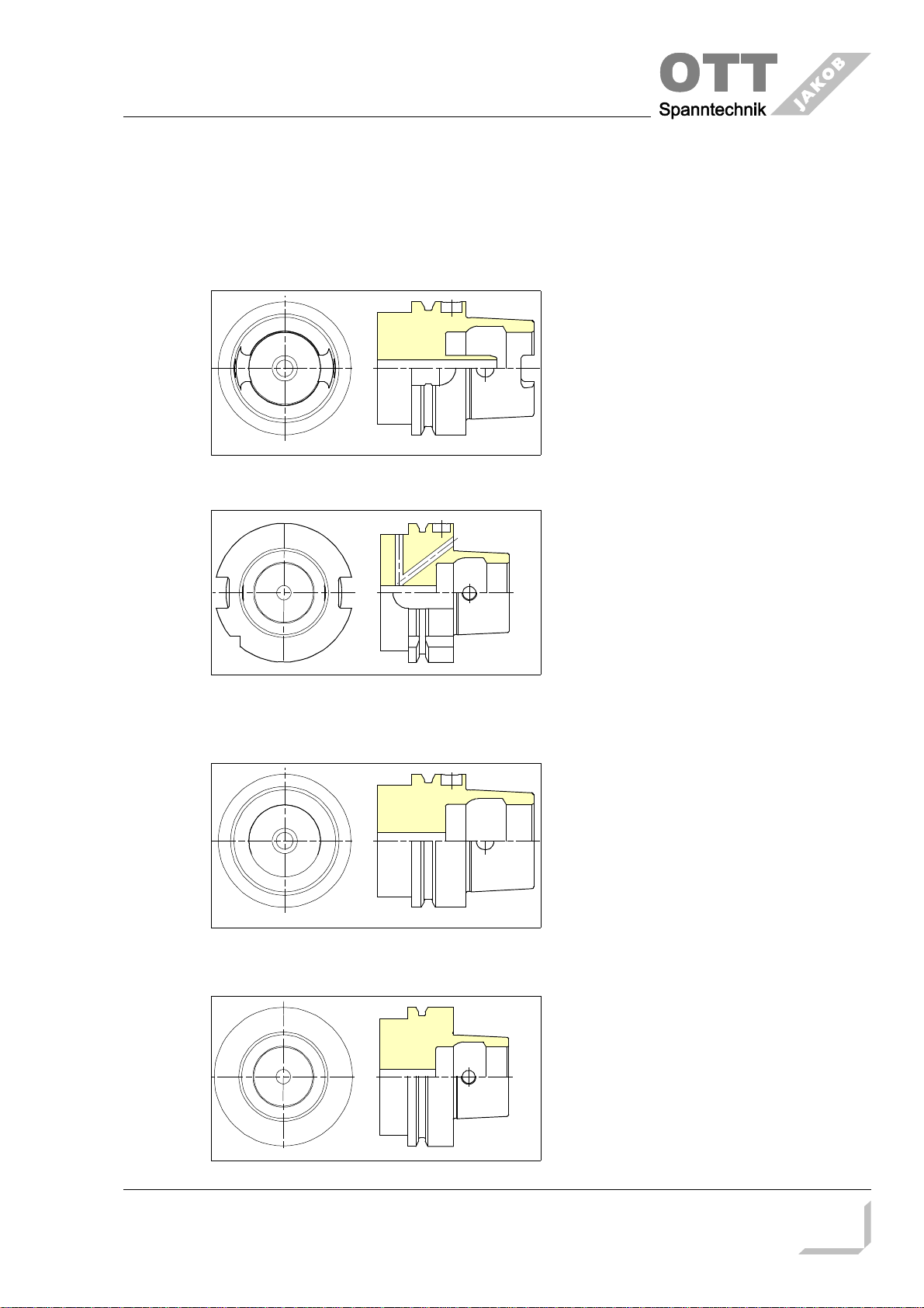
1.6 HSK-clamping unit form A.............................................................................................9
1.6.1 Dimension........................................................................................................................9
1.6.2 Order number HSK form A ...........................................................................................10
1.6.3 Draw bar HSK form A ...................................................................................................10
1.6.4 Spindle inside contour HSK form A ..............................................................................11
1.7 HSK-clamping unit form B..........................................................................................13
1.7.1 Dirmension.....................................................................................................................13
1.7.2 Order number HSK form B ...........................................................................................14
1.7.3 Draw bar HSK form B ...................................................................................................14
1.7.4 Spindle inside contour HSK form B ..............................................................................15
1.8 HSK-clamping unit form E..........................................................................................17
1.8.1 Dimension......................................................................................................................17
1.8.2 Order number HSK form E ...........................................................................................18
1.8.3 Draw bar HSK form E ...................................................................................................18
1.8.4 Spindle inside contour HSK form E ..............................................................................19
Änderungen im Sinne des technischen Fortschrittes vorbehalten! 95.600.019.D.E / 2006-03
2

Product Information
1.9 HSK-clamping unit form F...........................................................................................21
1.9.1 Dimension......................................................................................................................21
1.9.2 Order number HSK form F ............................................................................................22
1.9.3 Draw bar HSK form F ....................................................................................................22
1.9.4 Spindle inside contour HSK form F ...............................................................................23
2 Assembly .....................................................................................................................25
2.1 Assembly tool for HSK clamping unit.............................................................................25
2.2 Clamping unit.................................................................................................................26
2.2.1 Check after approx. 100 strokes ..................................................................................28
3 Operation .....................................................................................................................29
4 Maintenance.................................................................................................................30
4.1 Preventive maintenance schedule.................................................................................30
4.2 Wearing part list.............................................................................................................31
4.2.1 Grease for HSK-calmping unit.......................................................................................31
4.2.2 O-rings and lip seal parts...............................................................................................32
4.2.3 Repair clamping unit HSK B-E.......................................................................................33
4.3 Exchange of the lip seal ...............................................................................................35
4.4 Break of a gripper segment...........................................................................................35
4.5 Trouble shooting HSK....................................................................................................36
symbol explanation:
keep attention -
dangerous keep attention - malfunction
Änderungen im Sinne des technischen Fortschrittes vorbehalten! 95.600.019.D.E / 2006-03
3
ATTENTION
Important

Product Information
1 Product Description
1.1 Standard
hollow shaft taper ISO / CD 12164-1; form A
features:
•central, axial coolant supply with
KSM-tube
•keyways at the taper end
application:
•machining centers, milling machines
hollow shaft taper DIN 69893-2; form B
features:
•decentralized coolant supply over the
flange or central coolant supply
through coolant tube
•enlarged flange
•keyways at the flange
application:
•machining centers, heavy milling
machines
hollow shaft taper DIN 69893-5; form E
features:
•rotational symmetry without keyways
application:
•HSC-spindles
hollow shaft taper DIN 69893-6; form F
features:
•enlarged flange
application:
•HSC-spindles e. g. machining of
wood and plastic
Änderungen im Sinne des technischen Fortschrittes vorbehalten! 95.600.019.D.E / 2006-03
4

Product Information
1.2 Medium transfer
Änderungen im Sinne des technischen Fortschrittes vorbehalten! 95.600.019.D.E / 2006-03
5
2
1without transfe
r
cleanin
g
air for closed HSK-tool
axial transfer for open HSK-tool

Product Information
1.3 Ceiling speed
nominal size
25 32 40 50 63 80 100 125 160
tool standard
A- 57294 45989 37336 27201 20897 15466 12561 8596
B- - 46787 33115 25535 19223 14698 11184 8560
E80124 57279 45728 39367 32691 - - - -
F- - - 39170 31262 22967 - - -
min-1
1.4 Transferable torque
nominal size
25 32 40 50 63 80 100 125 160
tool standard
A- 14 24 48 97 190 365 710 1436
Nm
B- - 16 28 55 113 217 422 835
transferable
torque without
keyways
E7152756110----
F- - - 31 64 128 - - -
Änderungen im Sinne des technischen Fortschrittes vorbehalten! 95.600.019.D.E / 2006-03
6

Product Information
1.5 Forces at the HSK-clamping unit
1.5.1 Clamped position
1.5.2 Unclamped position
Änderungen im Sinne des technischen Fortschrittes vorbehalten! 95.600.019.D.E / 2006-03
7
Fs
p
F1
F0
F0
F
A
FL
H
0

Product Information
1.5.3 Diagram
1.5.4 Table
nominal size
25 32 40 50 63 80 100 125 160
tool standard
AFsp 5 6,8 11 18 28 45 70 115
F1max. 1,75 2,4 3,85 6 9,2 15 24,5 40
FA0,9 1,3 2,2 3,2 5,2 7 10,3 14,4
BFsp 5 6,8 11 18 28 45 70
F1max. 1,75 2,4 3,85 6,3 9,8 15,8 24,5
FA1 1,7 2,9 4,6 6,9 10 14,4
EFsp 2,8 5 6,8 11 18
F1max. 0,98 1,75 2,4 3,85 6,3
FA0,9 1,1 1,7 2,9 4,7
FFsp 6,8 11 18
F1max. 2,4 3,85 6,3
FA1,9 3,4 5,6
kN
Änderungen im Sinne des technischen Fortschrittes vorbehalten! 95.600.019.D.E / 2006-03
8
H [mm]
F
[
kN
]
F1
H1
F0
Hmax
H0
FL
FA
springforce
unclamp forc
e

Product Information
1.6 HSK-clamping unit form A
1.6.1 Dimension
Änderungen im Sinne des technischen Fortschrittes vorbehalten! 95.600.019.D.E / 2006-03
9
d
1
E.M.
A
a
1
l
7
SW
1
d
6
H
0
H
1
H
max.
A
= reference
g
au
g
e
= ejection
hollow-shaft-
taper spindle
drawbar shaft
lock screw SW
2
Limit the stroke of drawbar shaft to H
max.
!
32 40 50 63 80 100 125 160
[mm]
A0,5 0,5 0,5 0,5 0,5 0,5 0,5 1
E.M. ±0,1 8,5 8,5 10,5 10,5 13 13 16,5 17
7,5 8 9 10 11 12,5 15,8 24,5
5,1 5,6 6,4 7,4 8,3 9,15 10,8 17,5
12 15 18 22 27 36 46 55
3 4 4 5 6 6 14 16
19,5 27 26,5 31,5 31,5 34,5 40,5 56
d
1
Hmax.
H1
SW1
SW2
a1

Product Information
1.6.2 Order number HSK form A
d1clamping unit for
axial medium
transfer
clamping unit without
medium transfer; air is
possible; without picture
mounting tool
32 95.600.008.3.6 95.601.111.3.1
40 95.600.007.3.6 95.600.016.3.6 95.601.112.3.1
50 95.600.004.3.6 95.600.083.3.2 95.601.113.3.1
63 95.600.001.3.6 95.600.015.3.6 95.601.114.3.1
80 95.600.002.3.6 95.601.115.2.1
100 95.600.003.3.6 95.601.116.2.1
125 95.600.009.3.6 95.601.117.2.1
160 95.600.010.3.6 95.601.118.2.1
1.6.3 Draw bar HSK form A
Änderungen im Sinne des technischen Fortschrittes vorbehalten! 95.600.019.D.E / 2006-03
10
45°
d
11
Z
R0,
5
R0,2
R0,
5
l
1
4
1,
6
Z
G
11
l
11
l
12
d
12
d
13
l
1
3
0,
4
B0,02
0,
4
B
A
-B0,02
O-Ring groov
e
32 40 50 63 80 100 125 160
[mm]
-0,1 4,6 6 7,9 11,9 13,9 13,9 21,2 27,1
-----
-4g M6 M8 M10 M14x1,5 M16x1,5 M16x1,5 M24x1,5 M30x1,5
9 14 16 18,5 21,5 32 38 52
50 60 67 76 80 50 60 75
- - - - - 101 115 145
d
1
d11
d12 6,2g7 8,2g7 10,2g7 14,2g7 16,2g7 16,2h8 24,2h8 30,4h8
d13 18g7 25g7 32g7
G11
l11
l12
l13
l14 1+0,1 1,4+0,1 1,4+0,1 1,4+0,1 1,4+0,1 1,4+0,1 1,9+0,2 1,9+0,2

Product Information
1.6.4 Spindle inside contour HSK form A
Änderungen im Sinne des technischen Fortschrittes vorbehalten! 95.600.019.D.E / 2006-03
11
45°
d
4
l
6
l
7
d
5
X
0,4
A-B0,01
30°
±3'
R 0,2
20°
Y
0,5
b
1
A
-
B
0,0
5
W
0,
4
l
2
l
5
0,4
d
2
d
1
l
3
l
7
l
10
1:10
A
30°
l
8
l
9
bei
d
3
l
1
l
4
(2°51'45")
W
A-B0,002
X
A-B0,02
-0,5
Y
R1
R0,2
1,6
d
3
d
9
d
6
d
7
d
8
t
min. 5
tenons can be inserted or integrated into
spindle; when tenons are inserted the taper hole
may be conical over the total length l
1
casehardened
700+100 Rc 100
depth min. 0,8
+ 0,4
not convex
r
1
tangent to b
1
and d
4

Product Information
The dimensions in the clamping unit section are for spindle speeds up to 10000 rpm.
For higher spindle speeds we recommend to reduce the tolerance of dimension d8and
the runout. Please let us know if you need additional information.
* see update standard
** see ISO 1101 and ISO 3040
Änderungen im Sinne des technischen Fortschrittes vorbehalten! 95.600.019.D.E / 2006-03
12
32 40 50 63 80 100 125 160
ISO / CD 12164-2 *
[mm]
±0,05 6,8 7,8 10,3 12,3 15,8 19,78 24,78 29,78
23,998 29,998 37,998 47,998 59,997 74,997 94,996 119,996
H10 17 21 26 34 42 53 67 85
+0,1 23,28 29,06 36,85 46,53 58,1 72,6 92,05 116,1
+0,2 23,8 29,6 37,5 47,2 58,8 73,4 93,0 118,0
+0,2 16,5 20,5 25,5 33 41 51 64 81
3,2 4 5 6,3 8 10 12,5 16
+0,2 11,4 14,4 17,9 22,4 28,4 35,4 44,4 57,4
+0,2 13,4 16,9 20,9 26,4 32,4 40,4 51,4 64,4
0,8 0,8 1 1 1,5 1,5 2 2
+0,1 1 1 1,5 1,5 2 2 2,5 2,5
2,0 2,0 2,0 2,5 3,0 3,0 4,0 4,0
-0,05 1,5 2 2,5 3 4 5 6 8
t ** 0,0015 0,0015 0,0020 0,0020 0,0025 0,0030 0,0035 0,0035
clamping unit
[mm]
H6 17 21 26 34 42 53 67 85
+0,1 10,3 13,2 15,2 20,4 22,4 24,2 32 37,2
+0,1 6,6 8,6 10,6 14,6 16,6 18,4 25,4 32,4
+0,2 22,5 26,5 33 41,6 50 63 79 104
-0,2 62,5 78 84 94 98 124 149 188
±0,1 43 58 61 69 72 93 112,5 148
30 44 45 52 56 70 86 113
+0,2 3 3,6 3,6 4,2 4,2 4,2 4,7 4
d1
b1
d2
d3
d4
d5
l1
l2
l3
l4
l5
l6
l7±0,1
r1
d6
d7
d8
d9
l7
l8
l9js8 bei d3
l10

Product Information
1.7 HSK-clamping unit form B
1.7.1 Dirmension
Änderungen im Sinne des technischen Fortschrittes vorbehalten! 95.600.019.D.E / 2006-03
13
A
a
1
l
7
SW
1
d
6
H
0
H
1
H
max.
A
d
1
E.M.= reference gauge
= e
j
ection
hollow-shaft-
taper spindle
drawbar shaft
lock screw SW
2
Limit the stroke of drawbar shaft to H
max.
!
40 50 63 80 100 125 160
[mm]
A0,5 0,5 0,5 0,5 0,5 0,5 0,5
E.M. ±0,1 8,5 8,5 10,5 10,5 13 13 16,5
7,5 8 9 10 11 12,5 15,8
5,1 5,6 6,4 7,4 8,3 9,15 10,8
12 15 18 22 27 36 46
34 4 5 6 6 14
19,5 27 26,5 31,5 31,5 34,5 40,5
d1
Hmax.
H1
SW1
SW2
a1

Product Information
1.7.2 Order number HSK form B
d1clamping unit for axial
medium transfer clamping unit without
medium transfer; air is
possible; without picture
mounting tool
40 95.600.008.3.6 95.601.111.3.1
50 95.600.007.3.6 95.600.016.3.6 95.601.112.3.1
63 95.600.004.3.6 95.600.083.3.2 95.601.113.3.1
80 95.600.001.3.6 95.600.015.3.6 95.601.114.3.1
100 95.600.002.3.6 95.601.115.2.1
125 95.600.003.3.6 95.601.116.2.1
160 95.600.009.3.6 95.601.117.2.1
1.7.3 Draw bar HSK form B
Änderungen im Sinne des technischen Fortschrittes vorbehalten! 95.600.019.D.E / 2006-03
14
45°
d
11
Z
R0,5
R0,2
R0,5
l
1
4
1,
6
Z
G
11
l
11
l
12
d
12
d
13
l
1
3
0,
4
B0,0
2
0,
4
B
A
-
B
0,0
2
O-Ring groov
e
40 50 63 80 100 125 160
[mm]
-0,1
4,6 6 7,9 11,9 13,9 13,9 21,2
-- - - -
-4g
M6 M8 M10 M14x1,5 M16x1,5 M16x1,5 M24x1,5
9 14 16 18,5 21,5 32 38
50 60 67 76 80 50 60
- - - - - 101 115
d
1
d
11
d
12
6,2
g7
8,2
g7
10,2
g7
14,2
g7
16,2
g7
16,2
h8
24,2
h8
d
13
18
g7
25
g7
G
11
l
11
l
12
l
13
l
14
1
+0,1
1,4
+0,1
1,4
+0,1
1,4
+0,1
1,4
+0,1
1,4
+0,1
1,9
+0,2

Product Information
1.7.4 Spindle inside contour HSK form B
Änderungen im Sinne des technischen Fortschrittes vorbehalten! 95.600.019.D.E / 2006-03
A0,05
W
e1
e1
b1
b2
A0,05
0,4
l2
l30,4
d2
d1
l7
l10
1:10
A
30°
l8
l9d3
f1
W
A-B0,0025
X
A-B0,02
-0,5
Y
R1
R0,2
min. 5
1,6
d3
d5
d6
d7
d8
l1
0,2
2°51'45"-
AT3
2
X
0,4
A-B0,01
30°
±3'
R 0,2
20°
Y0,5
casehardened
700+100 Rc 100
depth min. 0,8+ 0,4
Relief per choice of customer
not convex
all aroun
d
at
15

Product Information
The dimensions in the clamping unit section are for spindle speeds up to 10000 rpm.
For higher spindle speeds we recommend to reduce the tolerance of dimension d8and
the runout. Please let us know if you need additional information.
* see update standard
Änderungen im Sinne des technischen Fortschrittes vorbehalten! 95.600.019.D.E / 2006-03
16
40 50 63 80 100 125 160
[mm]
9,9 11,9 15,9 17,9 19,9 24,9 31,9
11 1 1 2 2 2
24 30 38 48 60 75 95
0 0 0 0 0 0 0
-0,003 -0,003 -0,004 -0,004 -0,005 -0,006 -0,007
H10 17 21 26 34 42 53 67
16,2 20,2 25,2 31,7 40,2 50,2 62,7
max. 19,5 25,5 25,5 25,5 28,5 28,5 30,5
16,5 20,5 25,5 33 41 51 64
3,2 4 5 6,3 8 10 12,5
0,8 0,8 1 1 1,5 1,5 2
clamping unit
[mm]
+0,2 22,5 26,5 33 41,6 50 63 79
H6 17 21 26 34 42 53 67
+0,1 10,3 13,2 15,2 20,4 22,4 24,2 32
+0,1 6,6 8,6 10,6 14,6 16,6 18,4 25,4
-0,2 62,5 78 84 94 98 124 149
±0,1 43 58 61 69 72 93 112,5
30 44 45 52 56 70 86
+0,2 3 3,6 3,6 4,2 4,2 4,2 4,7
d1
E DIN 69063-2 1997-04*
b1+0,05
-0,05
b2
d2
d3
e1+0,2
0
f1
l1+0,3
0
l2
l3
d5
d6
d7
d8
l7
l8
l9js8 bei d3
l10

Product Information
1.8 HSK-clamping unit form E
1.8.1 Dimension
Änderungen im Sinne des technischen Fortschrittes vorbehalten! 95.600.019.D.E / 2006-03
17
d
1
E.M.
A
l
7
SW
1
d6
H
0
H
1
H
max.
A
a
1
= reference gauge
= ejection
hollow-shaft-
taper spindle
drawbar shaf
t
lock screw SW
2
Limit the stroke of drawbar shaft to H
max.
!
25 32 40 50 63
[mm]
A0,5 0,5 0,5 0,5 0,5
E.M. ±0,1 6,5 8,5 8,5 10,5 10,5
77,58 9 10
4,6 5,1 5,6 6,4 7,4
10 12 15 18 22
334 4 5
5,5 19,5 27 26,5 31,5
d1
Hmax.
H1
SW1
SW2
a1

Product Information
1.8.2 Order number HSK form E
d1clamping unit for
axial medium
transfer
clamping unit without
medium transfer; air is
possible; without picture
mounting tool
25 95.600.011.3.6 95.601.110.3.1
32 95.600.008.3.6 95.601.111.3.1
40 95.600.007.3.6 95.600.016.3.6 95.601.112.3.1
50 95.600.004.3.6 95.600.083.3.2 95.601.113.3.1
63 95.600.001.3.6 95.600.015.3.6 95.601.114.3.1
1.8.3 Draw bar HSK form E
Änderungen im Sinne des technischen Fortschrittes vorbehalten! 95.600.019.D.E / 2006-03
18
45°
d11
Z
R0,5
R0,2
R0,5
l14
1,
6
Z
G11
l11
l12
d12
0,4
B0,0
2
B
A
-
B
0,0
2
O-Ring groov
e
25 32 40 50 63
[mm]
-0,1 4,6 4,6 6 7,9 11,9
g7 6,2 6,2 8,2 10,2 14,2
-4g M6x0,5 M6 M8 M10 M14x1,5
10,5 9 14 16 18,5
45 50 60 67 76
+0,1 1 1 1,4 1,4 1,4
d1
d11
d12
G11
l11
l12
l14

Product Information
1.8.4 Spindle inside contour HSK form E
Änderungen im Sinne des technischen Fortschrittes vorbehalten! 95.600.019.D.E / 2006-03
19
0,4
l2
l30,4
d
2
d1
l7
l10
1:10
A
30°
l8
l9
A-B0,0025
X
A-B0,02
-0,5
Y
R1
R0,2
min.5
1,6
d
3
d5
d6
d7
d8
l4
l1
d3
2°51'45"-
AT3
2
X
0,4
A-B0,01
30°±3'
R 0,2
20°
Y0,5
not convex at
casehardened
700+100 Rc 100
depth min. 0,8+ 0,4

Product Information
The dimensions in the clamping unit section are for spindle speeds up to 10000 rpm.
For higher spindle speeds we recommend to reduce the tolerance of dimension d8and
the runout. Please let us know if you need additional information.
* see update standard
Änderungen im Sinne des technischen Fortschrittes vorbehalten! 95.600.019.D.E / 2006-03
20
25 32 40 50 63
[mm]
19 24 30 38 48
-0,001 -0,001 -0,002 -0,003 -0,003
-0,003 -0,003 -0,004 -0,006 -0,007
13 16 20 25 32
2,5 3,2 4 5 6,3
0,5 0,8 0,85 1 1
13,5 16,5 20,5 25,5 33
clamping unit
[mm]
H10 14 17 21 26 34
+0,2 18 22,5 26,5 33 41,6
H6 14 17 21 26 34
+0,1 - 10,3 13,2 15,2 20,4
+0,1 6,4 6,6 8,6 10,6 14,6
-0,2 40 62,5 78 84 94
±0,1 25,5 43 58 61 69
18,5 30 44 45 52
+0,2 - 3 3,6 3,6 4,2
d1
DIN V 69063-5 1996-01 *
d2
l1
l2
l3
l4
d3
d5
d6
d7
d8
l7
l8
l9js8 bei d3
l10
Table of contents
Other jakob Power Tools manuals
Popular Power Tools manuals by other brands

N.KO
N.KO UZ 12 Ultralight Instructions for use and maintenance

STEINEL
STEINEL S-Former E0 instruction manual

Central Forge
Central Forge 40728 Assembly and operation instructions

Valex
Valex PT2001 Safety and operating instructions

ACDelco
ACDelco ARM601-3 Product information manual

Makita
Makita DOUBLE INSULATION 4320 instruction manual