JAMAR Technologies RAC Plus Series User manual

i

RAC Plus User’s Manual
ii
iii
LIMITED WARRANTY
JAMAR Technologies, Inc. warrants the RAC Plus series instruments for a period
of ve (5) years limited warranty against defects in material and workmanship as
follows: rst year, parts and labor; years two through ve, parts only, at labor
charge. Sensors, cables, connectors, brackets and other hardware are warranted
for ninety (90) days.
JAMAR Technologies, Inc. warrants each new instrument manufactured by the
company to be free from defective material and workmanship and agrees to remedy
any such defect. At its option, it may furnish a new part in exchange for any part
of any instrument of its manufacture which, under normal installation, use and
service discloses such defect. The instrument must be returned to the JAMAR
factory or authorized service agent intact, for examination, with all transportation
charges prepaid.
This warranty does not extend to any products which have been subject to misuse,
neglect, accident, incorrect wiring not our own, improper installation or use in
disregard of instructions furnished by JAMAR. This warranty does not extend
to products which have been repaired or altered outside the JAMAR factory or
authorized service agent.
In no event shall JAMAR Technologies, Inc. be liable for any damages arising from
the use of this product including damages arising from the loss of information.
This warranty is in lieu of all other warranties expressed or implied and no
representative or person is authorized to assume for JAMAR Technologies, Inc.
any other liability in connection with the sale or use of JAMAR products.
JAMAR Technologies, Inc. reserves the right to make improvements on the product
and/or specications at any time without notice.
Questions concerning this warranty or any JAMAR Technologies, Inc. product
should be directed by e-mail, mail or telephone to:
JAMAR Technologies, Inc.
151 Keith Valley Road
Horsham, PA 19044
215-491-4899
Copyright 2006 by JAMAR Technologies, Inc.

RAC Plus User’s Manual
ii
iii
Table of Contents
Volume 1.2 May 2006
If you have any questions about the use of the RAC Plus devices, please
call the following number:
1-215-491-4899
Monday — Friday, 8:00 AM to 5:00 PM Eastern time
You may also contact us by e-mail at:
For more information on our products, or for the latest news in product
development, visit our web site at:
www.jamartech.com
For support information specic to the RAC Plus devices, go to:
www.jamartech.com/RACPlusSupport.htm
Address any correspondence to:
JAMAR Technologies, Inc.
151 Keith Valley Road
Horsham, PA 19044-1411

RAC Plus User’s Manual
iv
1-1
Table of Contents
Technical Support ........................................................... iii
Introduction to the RAC Plus I and Plus II..................................... 1-1
What are the RAC Plus I and Plus II?..................................... 1-2
How Do They Work? ......................................................... 1-3
Quick Start Guide ......................................................... 1-4
Installation ......................................................... 2-1
Before You Begin ......................................................... 2-2
Installing the Modular Distance Sensor.................................. 2-3
Installing the RAC Instrument................................................ 2-7
Calibration ......................................................... 3-1
Automatic Calibration Procedure ........................................... 3-2
If Your RAC Fails to Calibrate................................................ 3-5
Manual Calibration Procedure ................................................ 3-7
Key Functions & Operating Procedures.......................................... 4-1
RAC Plus Key Functions ........................................................ 4-2
RAC Plus Menu Functions ..................................................... 4-5
RAC Plus Additional Features .............................................. 4-15
Troubleshooting ......................................................... 5-1
Frequently Asked Questions ................................................... 5-3
Appendix ........................................................ A-1
Connection and Output Formats ............................................ A-2
Specications ........................................................ A-4
Glossary ........................................................ A-5
Vehicle Calibration Record .................................................... A-7

RAC Plus User’s Manual
iv
1-1
Chapter 1
Introduction
to the
RAC Plus I & Plus II
Chapter 1 — Introduction

RAC Plus User’s Manual
1-2
1-3
What are the RAC Plus I and Plus II?
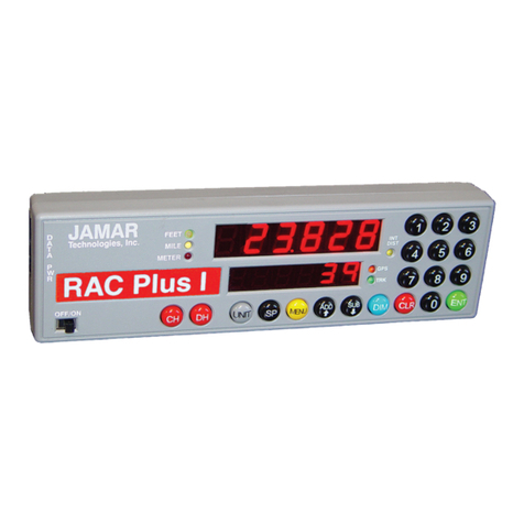
The JAMAR Technologies Road Analysis Computer (RAC) Models Plus I
and Plus II are accurate, easy-to-use distance measuring instruments (DMI)
that use state-of-the-art microprocessor technology. The RAC Plus I and
RAC Plus II DMIs have been designed with features to provide you with
a versatile and functional instrument that can be learned in a very short
time.
The RAC Plus II contains all of the features of the RAC Plus I with the
addition of memory storage and data output. This allows for saving of in-
formation for later download to a computer.
Fig. 1.1 — RAC Plus I and RAC Plus II Distance Measuring Instruments

RAC Plus User’s Manual
1-2
1-3
Chapter 1 — Introduction
How do they work?
To use the RAC Plus I or Plus II DMI to accurately measure distance, either
a modular distance sensor (MDS) or mechanical transmission sensor is
used to send pulses to the DMI. The Quick-Kit, which is a modied version
of the MDS, can also be used.
Most newer vehicles (1992 and newer) have an electronic distance/speed
sensor inside the transmission which sends pulses to the vehicle's on-
board computer for use in the speedometer, ABS braking system, engine/
transmission control, etc. These vehicle-generated signals can be as many
as 100,000 pulses per mile, which is far more than the RAC needs to ac-
curately measure distance. Further, since the vehicle manufacturers are not
concerned with accurate distance and speed readings at very low speeds
(your speedometer may not move below 5 mph), the signal strength at these
low speeds is extremely minimal.
The MDS is not just an improvement over other electronic interface type
sensors. First, and foremost, its proprietary circuitry allows more accurate
slow speed measurements by sensing signals as low as 10 Mv from the
vehicle speed sensor. Second, it is designed to be mounted under the ve-
hicle dashboard rather than under the hood as with other interface sensors.
This gets the MDS out of a severe heat and moisture environment and into
a more controlled environment. Third, our exclusive internally generated
Sensor Test and Tap Test features allow the user to verify proper sensor and
instrument operation. Finally, the modular design simplies installation.
Older vehicles with mechanical speedometer cables use the mechanical
transmission sensor, which is screwed on to the transmission. For infor-
mation on how to install this type of sensor, refer to the instructions that
came with the sensor.
The next chapter details how to install a modular sensor into your vehicle.
If your already have a sensor installed, you may skip to Chapter 3 for infor-
mation on calibrating your RAC.

RAC Plus User’s Manual
1-4
2-1
Quick Start Guide
The RAC Plus I and II DMIs will allow you to accurately measure distance
quickly and easily. However, before you can do this a few basic steps must
be taken to ensure that you get the optimum performance from your in-
strument.
Step 1
Install your RAC and its modular sensor. Refer to Chapter 2 for detailed
instructions on this. If you would like to have the equipment professionally
installed, contact a garage or speedometer shop in your area.
Step 2
Calibrate your instrument. Refer to Chapter 3 for detailed instructions on
how this is done. Your RAC will not accurately measure distance unless
it is properly calibrated.
Step 3
Perform a test measurement with your vehicle. Once your RAC has been
calibrated, you should perform a test measurement over a known distance.
This will ensure that the instrument has been calibrated correctly.
To do a test measurement, drive to your starting point and stop. Turn on the
RAC and wait until zero is shown on the larger, upper display and CH is
shown on the smaller, lower display. Next, press the CH (count hold) button
to release the instrument from count hold and then drive the distance to be
measured. Stop and/or press the CH button once you reach the end of the
distance to be measured.
Step 4
Familiarize yourself with the features and options of the instrument that
you will be using. Refer to Chapter 4 for more detailed instructions on the
functions and procedures of the RAC Plus I or II.
Step 5
Practice. Before attempting to use the instrument on a job, be sure you are
comfortable with how to operate it.

RAC Plus User’s Manual
1-4
2-1
Chapter 2
Installation
Chapter 2 — Installation

RAC Plus User’s Manual
2-2
2-3
Before You Begin
Note: The following instructions are for installing a RAC with a Modular
Distance Sensor. If you are installing a different type of sensor, refer to the
instructions that came with the sensor itself.
The JAMAR RAC Plus I and Plus II distance measuring instruments (DMI)
are very reliable instruments. However, there can be some external variables
that could affect proper operation and the ability to accurately measure
distance traveled. By observing a few simple precautions you will be able
to eliminate potential problems.
• Do not install wires near any object that could cause stray pulses to
be picked up, such as the alternator, spark plugs or engine coil.
• Do not install the wires or sensor near any objects that will get hot,
such as the manifold. The installation wires or sensor can melt if they
are too close to a heat source.
• Do not install wires near any objects that could vibrate and cut the
wires.
• Tire pressure should be the maximum suggested by the tire manu-
facturer, typically 32-35 PSI cold. The tire should have ample tread
depth. Steel belted radial tires are highly recommended.
• Drive the vehicle 3 to 5 miles (depending on climate) to warm the
tires up to normal operating temperatures prior to calibrating your RAC.
Refer to Chapter 3, Calibration for more detailed instructions.

RAC Plus User’s Manual
2-2
2-3
Installing the
Modular Distance Sensor
Most vehicles (1992 and newer) have an electronic speed output rather than
a mechanical speedometer cable coming from the transmission. With these
vehicles you will need to install either a Modular Distance Sensor (MDS)
Vehicle Kit or a Modular Distance Sensor Quick Kit. Use the following
instructions for installation of the MDS Kits.
1. Find a location under the vehicle
dashboard that will allow fairly easy
access to the MDS. Do Not mount the
MDS on the heater ducts or where the
heater vents will blow directly onto it.
Attach the MDS using the nylon ties or
Velcro provided, as shown in Fig. 2.1.
2. Locate the 2 wires coming from the
Vehicle’s Speed Sensor (VSS).
• On most Ford and Chrysler pick-up trucks, the best place is on the rear
end differential housing using the rear ABS signal. On 2005 and later
Ford trucks, connect at the top rear of the transmission tail shaft (on
4x4 where the transmission meets the transfer case) with the JAMAR
red wire to the vehicle's blue/yellow wire. Leave the JAMAR black
wire disconnected.
• On General Motors pick-up trucks, the best place is the VSS at the
transmission.
• On many vehicles (both trucks and autos)
you can go to the cruise control signal or to
the vehicle ECU which is often located under
the dashboard.
(Note: Vehicle wiring changes from year to year
and model to model. For technical support in locating the vehicle speed
signal wire call JAMAR at 215-491-4899. Your local Auto/Truck dealer can
also usually tell you where the VSS can be located on your vehicle.)
3. Route the red and black end of the 20’ grey VSS cable through the re-
wall. This can usually be done by using an existing rubber grommet where
Chapter 2 — Installation
All wires and the
MDS itself should
be kept away from
any heat source that
could cause melting.
Fig. 2.1
MDS Mounted Under Dash

RAC Plus User’s Manual
2-4
2-5
other wires pass through the rewall. If you cannot locate an existing hole,
CAREFULLY drill a small hole large enough for both the VSS cable and
the +12Volt/Ground wires. EXTREME CAUTION must be taken to insure
you do not drill into anything mounted on the opposite side of the rewall
or cut any existing wiring.
Use the cable ties provided while routing the cable to the location for getting
the speed signal that you previously identied. Attach the red and black wires
of the VSS cable to the vehicle’s speed sensor wires using the tap splice
connectors provided. The red wire goes to the high-speed signal wire; the
black goes to the low speed signal wire or chassis ground.
NOTE: The tap splice connectors are supplied for convenience for ini-
tial installation. However, we recommend that once the installation is
completed and you have veried the instrument is working properly,
remove the tap splice connectors and solder the connections. Insulate
using electrical tape or silicone.
4. Plug the connector of the VSS cable
into the hole labeled VSS Input located
on the right side of the MDS, as shown
in Figure 2.2.
5. Route the black DMI cable from the MDS to the desired instrument loca-
tion. This will usually be routed between the doorpost and the dashboard.
Make sure the cable will not be pinched when closing the door. If the instru-
ment is going to be mounted to the front of the dashboard, you may want
to bring the cable straight up the front of the dash. There is adequate cable
length to allow mounting the DMI in
any desired location inside the vehicle.
Plug the cable into the MDS jack la-
beled To DMI, as shown in Figure 2.3. It
does not matter which end of the cable
is plugged into the MDS or DMI.
6. Route the Red (+12 Volts) and Black (Ground) power cables directly
to the vehicle’s battery. This can be done using the same feed through lo-
cation that was used for the VSS Cable. If, out of convenience, you elect to
obtain the +12VDC and ground from a fuse panel or other location under
the dashboard, make sure it is a constant 12 volt source and not one that
Fig. 2.2 –VSS Plug-in
Fig. 2.3 –DMI Plug-in

RAC Plus User’s Manual
2-4
2-5
Chapter 2 — Installation
is switched off with the ignition key.
We also recommend the circuit should
have as few devices as possible to avoid
voltage uctuations from Turn Signals,
Brake Lights, etc. Plug the power cable
into the hole labeled Power on the
MDS, as shown in Figure 2.4.
A diagram of the complete installation for the MDS is shown in Figure 2.6
on page 2-6.
Adjusting the Vehicle Speed Sensor Pulse Rate
The signal pulses coming from the vehicle speed sensor are generated for use
by the vehicle’s computer, engine/transmission control, fuel management,
ABS brakes, etc. The pulse rate can vary from 4,000 to in excess of 100,000
pulses per mile. The MDS will condition and amplify these pulses for use by
the DMI. Since the higher pulse rates
are not required for accurate distance
measurements, the MDS incorporates a
divider circuit to reduce the pulse rate.
This is done by adjusting the rotary
switch on the front of the MDS, as
shown in Figure 2.5.
Although your particular vehicle may
vary, generally Chrysler and Ford vehicles use a 4 to 1 ratio (position 4 on
the switch) while General Motors vehicles use a 16 to 1 ratio (position 16 on
the switch). To adjust the ratio, use a small screwdriver to rotate the switch
until the slot in the switch points to the desired ratio. Note that when the
switch is turned counter-clockwise until it stops, it is at the 1 to 1 ratio.
The adjustments go from 1 to 1 (1 pulse into the sensor, 1 pulse out) through
64 to 1 (64 pulses into the sensor, 1 pulse out). The Tap Test positions
are explained in the troubleshooting section on page 3-4. You may need
to adjust the ratio again based on the results of the calibration procedure
described in Chapter 3. Any time you change the pulse ratio, you will need
to re-calibrate the DMI.
Once you have installed the MDS, install your RAC Plus using the instruc-
tions on page 2-7.
Fig. 2.4 –Power Plug-in
Fig. 2.5
Rotary Switch Adjustment

RAC Plus User’s Manual
2-6
2-7
The number of pulses per mile from
a vehicle will vary with the make
and model. Your calibration factor
should be between .500 and 1.200.
If not, adjust the rotary switch then
recalibrate to reach a calibration
number within this range.
Note: If the speedometer does not
respond to vehicle movement, sim-
ply reverse the RED and BLACK
wires to correct polarity.
Most vehicles should have a 2-wire output from the VSS.
Dodge & Ford trucks may have the VSS located on top of the
rear end housing instead of at the transmission. It will normally
be a 2-wire output, small gauge wire.
Connect the red and black wires of the long 20’ VSS cable to
the wires from the vehicle’s speed sensor. Crimp-on tap splice
connectors are supplied for convenience on initial installation.
However, we recommend removing the tap splice connectors
and reconnecting using wire to wire solder once you are sure
all connections to the VSS are proper. Insulate with sealant/
electrical tape as needed.
Fig. 2.6 –MDS Installation Diagram
Vehicle Speed
Sensor (VSS)
Fire
Wall
Fire
Wall
Tap Splice
Connectors
Battery
RAC Connector
Fuse
Ground Black
+12 VDC
Red

RAC Plus User’s Manual
2-6
2-7
Installing the RAC Instrument
The compact case design of the RAC Plus allows mounting of it in a num-
ber of convenient locations. Popular locations include on the front of the
dashboard, above or below the dashboard, or on the windshield using the
optional windshield mounting bracket. Wherever you decide to mount the
instrument, remember it should be within easy reach and the display should
be visible without obstructions.
It is most common to mount the RAC
to the front of the dashboard using the
Velcro provided. Two plastic 'L' brack-
ets are also provided to facilitate mount-
ing to the top of the dashboard if that is
your preferred location. For best results,
attach the 'L' bracket so that the bottom
of the 'L' is facing away from the RAC
as shown in gure 2.7.
Using the two 'L' brackets allows you to compensate for curved dashboards
even if it requires the RAC to be mounted on a left or right slope.
After mounting the RAC, plug the black cable from the MDS into the RAC.
You may want to consider allowing enough slack in the cable to permit a
passenger to hold/operate the RAC if necessary. Regardless of the mounting
location, Velcro strips are provided for quick, easy mounting & removal
of your RAC.
Once you have mounted your RAC and connected it to the MDS, proceed
to the calibration instructions in the following chapter.
Fig. 2.7 - 'L' Bracket Side View
Fig. 2.8 - 'L' Bracket on Curved Dashbaord

RAC Plus User’s Manual
2-8
3-1

RAC Plus User’s Manual
2-8
3-1
Chapter 3
Calibration
Chapter 3 — Calibration

RAC Plus User’s Manual
3-2
3-3
Automatic Calibration Procedure
In order to accurately measure distance, your RAC Plus must know the exact
distance that the vehicle will travel based on pulses from the vehicle's speed
sensor. The calibration number is the automatic calculation that represents
the number of pulses received over a set distance. This number, once cal-
culated, will remain accurate until a change to
the vehicle occurs, such as different size tires are
put on the vehicle, tire wear, tire pressure change,
etc. Such changes will require a re-calibration in
order to maintain proper accuracy.
The RAC Plus has the ability to store four (4) separate vehicle calibration
numbers in memory. This simplies sharing one instrument between up to
four different vehicles.
In order to calculate the calibration number for your particular vehicle, you
must rst establish a calibration course. The length of the course can be
any known distance more than 500 feet. One thousand feet is ideal, but the
course can be any distance over 500 feet (for example, 623 feet from pole
to tree). Your course should be straight and accurate, so take the time to
measure the course using a 100' tape or hand wheel. Mark the beginning and
ending points so they can be seen from inside your vehicle. Remember, the
course length can be any accurate distance over 500 feet, so for convenience
you could use a telephone pole or other marker as reference point.
Note: If you are using the Metric unit of measuring, laying out the
calibration course in feet is required to obtain the most accurate cali-
bration number.
Step 1
Slide the ON/OFF switch to ON. Your
RAC will perform a brief Self Test.
The current calibration number will
be shown in the larger, upper display
(D-1) and CF U(vehicle 1, 2, 3 or 4) in
the smaller, lower display (D-2). This is
displayed for 3-4 seconds while a tone
sounds, then 0 is shown in D-1 (0.000 if the mile or meter unit of measure-
ments is selected) while CH is shown in D-2.
Your RAC Plus must
be calibrated in
order to accurately
measure distance.
Fig. 3.1
Calibration Display on Start-up

RAC Plus User’s Manual
3-2
3-3
Step 2
Press the Menu key, the # 1 key and
Enter. At this point, the unit of mea-
surement will automatically change to
feet. You can then select the vehicle
number that this calibration will be
for by using the 1 through 4 numeric
keys.
Step 3
Once the vehicle number has been se-
lected, press Enter. Key in the course
length (in feet) to be used for the cali-
bration using the number keys, then
press Enter again.
Step 4
Using a reference point on your vehicle (i.e. the window post, door handle,
your shoulder, etc.), align your vehicle to the beginning course marker.
Step 5
Press the CH key and drive away. As you drive,
the pulses received from the vehicle are being
shown in D-1. This is not the distance being
traveled, so don't panic when the display doesn't
equal the actual length of your calibration course.
When you reach the end of the course, stop your
vehicle so you are exactly aligned (using the same
reference point in the vehicle) with the end course marker.
Step 6
Press the CH key. The calibration factor
will then be shown in D-1. You should
record the calibration number, vehicle
number and date in the Appendix of
this manual on page A-7. It is also
recommended that you put this same
information on a piece of tape attached
to the inside of the vehicle's glove box.
Chapter 3 — Calibration
If your RAC does
not count during the
calibration procedure,
refer to the trouble-
shooting section on the
next page.
Fig. 3.2
Vehicle Number Selection
Fig. 3.3 - Enter Course Length
Fig. 3.4
Calibration Number Displayed

RAC Plus User’s Manual
3-4
3-5
Step 7
Press Enter and the unit of measurement will return to your desired unit of
feet, mile or meter. Press Enter again to exit the menu function and return to
normal operation. Your calibration number for the vehicle selected is now
stored in the RAC's nonvolatile (permanent) memory. The calibration num-
ber will stay in memory for more than 50 years, or until you re-calibrate or
manually change the data. You are able to view the calibration number and
unit (vehicle) number every time you power up the RAC.
You should rerun the calibration course, in the normal mode, to verify the
calibration for your vehicle. Press the CH key prior to measuring. If this is
the rst time you have calibrated a DMI, you may want to run the course a
couple of times to practice being properly aligned when starting and stop-
ping at the course markers.
Important: Ideally, the calibration number used
should be between .500 and 1.200. If your cali-
bration number is below this range, you need to use
a higher division factor such as 16 on the Modular
Distance Sensor (MDS). Of course, if your calibra-
tion number is too high, you can lower the number
by using a lower number such as 1 on your MDS.
This is done by adjusting the rotary switch on the
MDS so the slot points to 1, 2, 8, 16, 32 or 64.
Any time you adjust the rotary switch setting, you must re-calibrate to
get the correct calibration number. Changing the switch setting will not
change the calibration number, only the number of pulses being received
by the RAC.
Refer to the Adjusting the Vehicle Speed Sensor Pulse Rate section in Chap-
ter 2 for more information on this. Several calibration runs may be necessary
to determine which division factor is best for your vehicle.
Your calibration
number should be
between .500 and
1.200. If not, you
need to adjust the
rotary switch on
your MDS.
This manual suits for next models
2
Table of contents
Other JAMAR Technologies Measuring Instrument manuals

JAMAR Technologies
JAMAR Technologies TRAX Apollyon User manual

JAMAR Technologies
JAMAR Technologies RAC Geo II User manual

JAMAR Technologies
JAMAR Technologies TRAX I User manual

JAMAR Technologies
JAMAR Technologies DB-100 User manual

JAMAR Technologies
JAMAR Technologies RAC Plus I User manual

JAMAR Technologies
JAMAR Technologies Black Cat II User manual