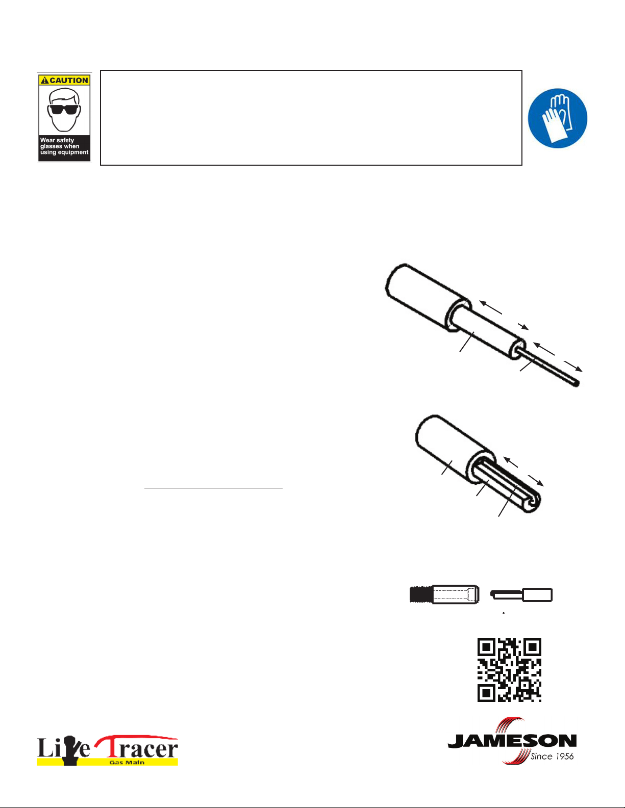
Traceable Fiberglass Rodder - Unit has 1/4” diameter rod with permanent
5/16” diameter end ferrule, Rod has copper trace wire embedded in berglass
core and is coated with polypropylene jacket for safety and durability.
Accessory Kit - Canvas Storage Bag, Grounding Cable, 3 Screws,
11 O-Rings, Rod Lubricant, Hex Key Driver, Adhesive, Replacement
End Ferrule, Spring Leader
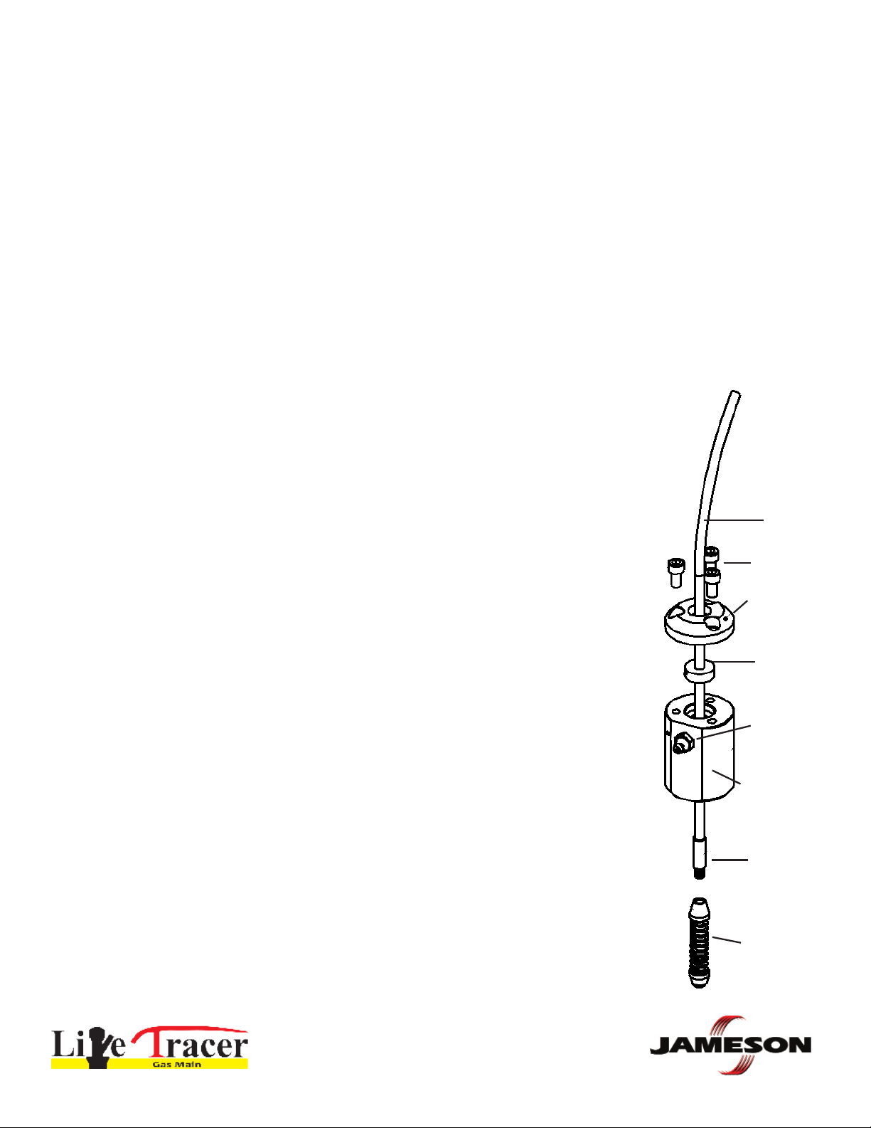
Stufng Box - Designed with custom o-ring to provide seal when
rod is inserted into pressurized lines for use up to 100 psi. Includes
4” pipe nipple with 1” NPT thread.
NOTICE
The components of the Live Tracer system are
specically designed to work exclusively with
each other.
The use of these components individually or in
combination with other non-Jameson tools or
accessories is not recommended and will not
guarantee the safety or effectiveness of the
system.
Required tools not included in this kit:
Gas leak detector / soap solution
Transmitter and Receiver for locating
Wrenches, channel locks
Various pipe ttings (may be required to adapt 1” NPT to your specic tting)
Teon tape / pipe dope
Grease gun with 1/4” button tting
Read and understand these operating and safety
instructions before using or servicing this equip-
ment.
Failure to follow instructions could result in an
accident causing serious injury. Do not allow chil-
dren or untrained personnel to use this equipment.
Follow your company installation procedures.
Specic parts and accessories
may vary according to your
company procedures.
Part Number
16-14-600-GL
Sold Separately
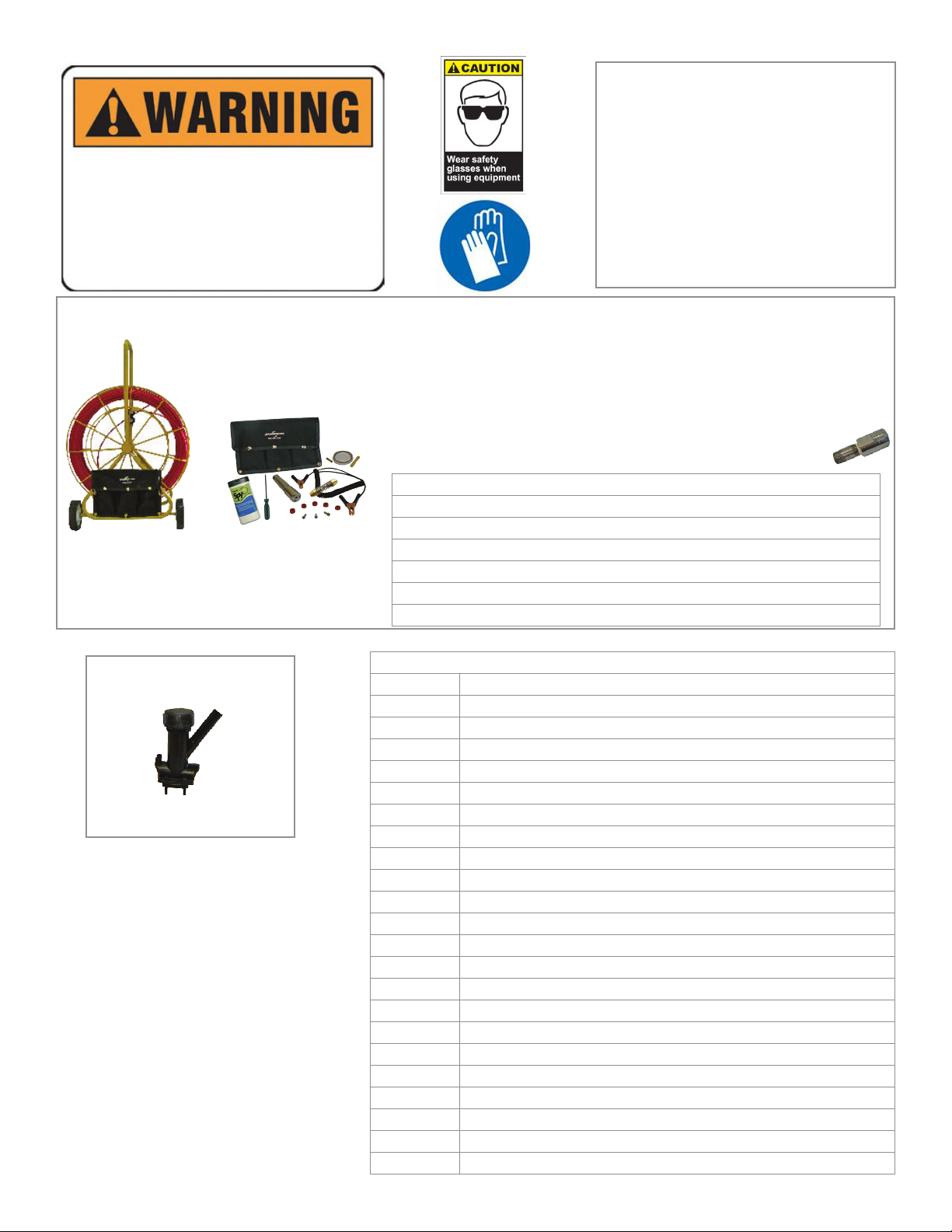
Electrofusion Insertion
Tapping Tee
Live Tracer Kit
Live Tracer Accessories - Sold Separately
16-2-TEE Electrofusion Tapping Tee for 2” Gas Main (4.7 mm resistor terminals)
15-WIPE Lubricating Wipes - Feeding Rod into Stufng Box
16-AWIPE Large Alcohol Wipes, 60 ct. - Clean Pipe for Electrofusion
16-169 Spring Leader
16-168 Flexible Sonde Adapter - Attaches Sonde to Rod
16-170 O-Ring Replacements, 10 ct.
16-SB Stufng Box, Three Screws, Six O-Rings
16-HVTAP HV Tap Tool
16-CW HVTT Cap Wrench
16-EFC-1 1” IPS Electrofusion Coupling (4.7 mm resistor terminals)
16-1HSCR Hand Scraper - Prepare Pipe for Electrofusion
16-RSCR 2” IPS Rotary Scraper - Prepare Pipe for Electrofusion
16-1PSCR 1” Poly Peeler - Prepare 1” Pipe (PUP)
16-TC HVTT Test Cap
16-TCG HVTT Test Cap with Gauge
16-HVTTR HVTT Tool Ratchet Handle
16-PROC Processor
16-PUP-12 PUP Extension Valve Assembly (12” Lead)
16-FLEX Flex Riser Valve Assembly
16-146 End Ferrule Replacement Kit
16-B7105 1” X 24” IPS, PE4710 Bronze Male Thread Transition
16-B7110 1” X 24” CTS, PE4710 Bronze Male Thread Transition
16-45ELB 45º Elbow, 1” IPS