J&W G31 + ICH7 Chipset User manual

User’s Manual
G31+ICH7 Chipset
Socket LGA755 Processor Mainboard
G31 Series
Rev: 1.3, Nov 2007
P/N: 88ENG31A03

Disclaimer
The intellectual property of this manual belongs to our company. The ownership of all of the
products, including accessories and software etc. belong to our company. No one is permitted to
copy, change, or translate without our written permission.
We compiled this manual based on our careful attitude, but we can not guarantee the accuracy
of the contents. This manual is purely technical documentation, without any hint or other
meanings, and we won't commit users' misunderstanding of the typesetting error.
Our products are in continuous improvement and updating, Therefore, we retain the right that
we won't give notice to the users in future.
Copyright
All of the trademark in this manual belong to their own registered company.
All of the products name is only for identication, its title belongs to its manufacturer or brand
owner.

Table of Contents
Chapter 1 Introduction ...........................................................................................
3
1.1 Package Checklist ...............................................................................................................
3
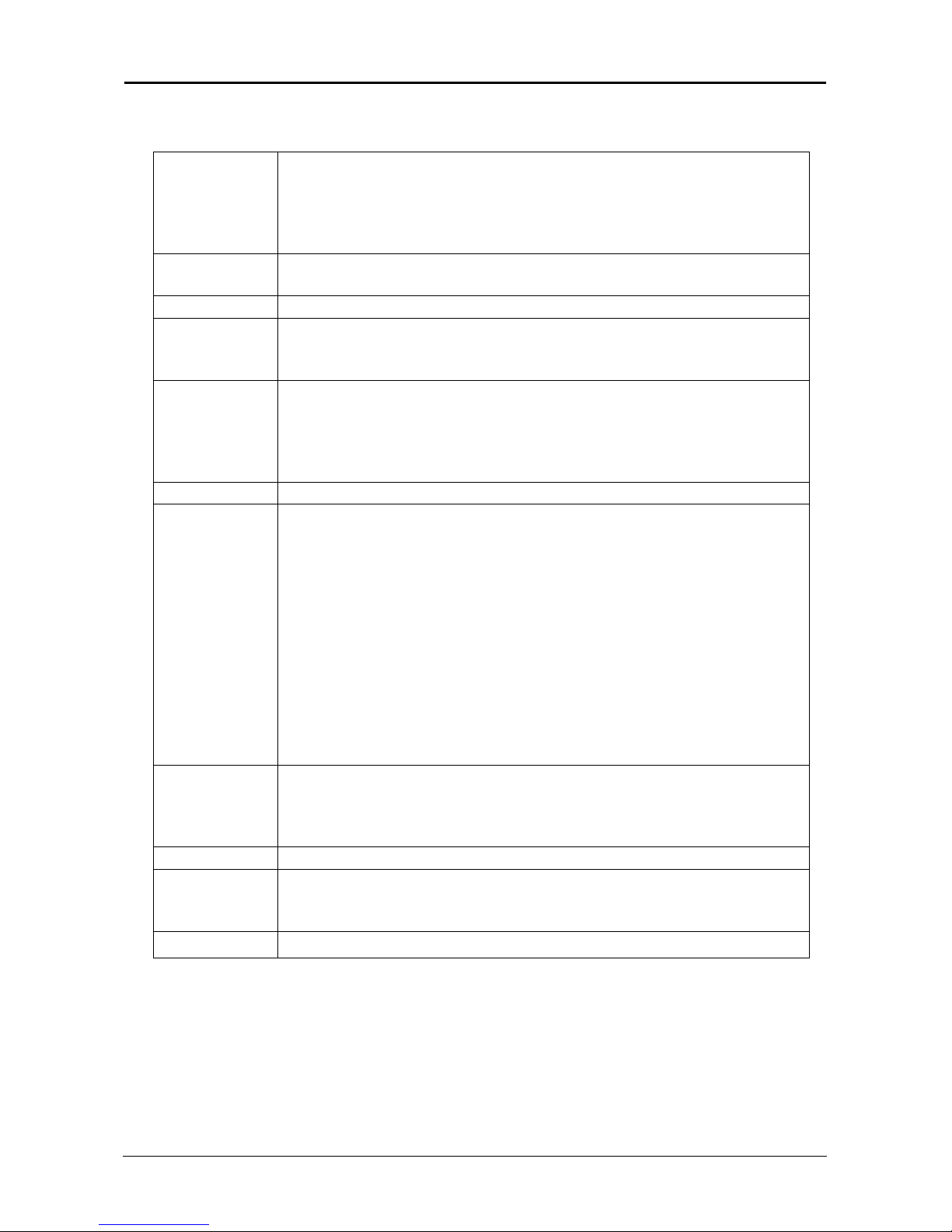
1.2 Specications ...................................................................................................................... 4
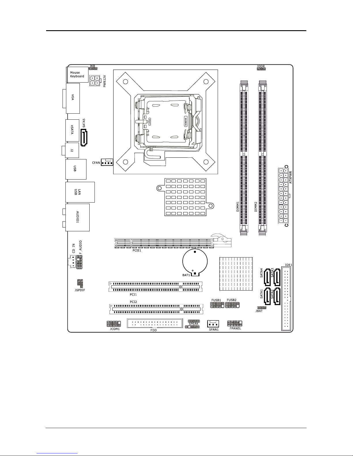
1.3 Mainboard Layout ...............................................................................................................
6
1.4 Connecting Rear Panel I/O Devices
.............................................................................
8
Chapter 2 Hardware Setup ......................................................................................
9
2.1 Choosing a Computer Chassis ..............................................................................................
9
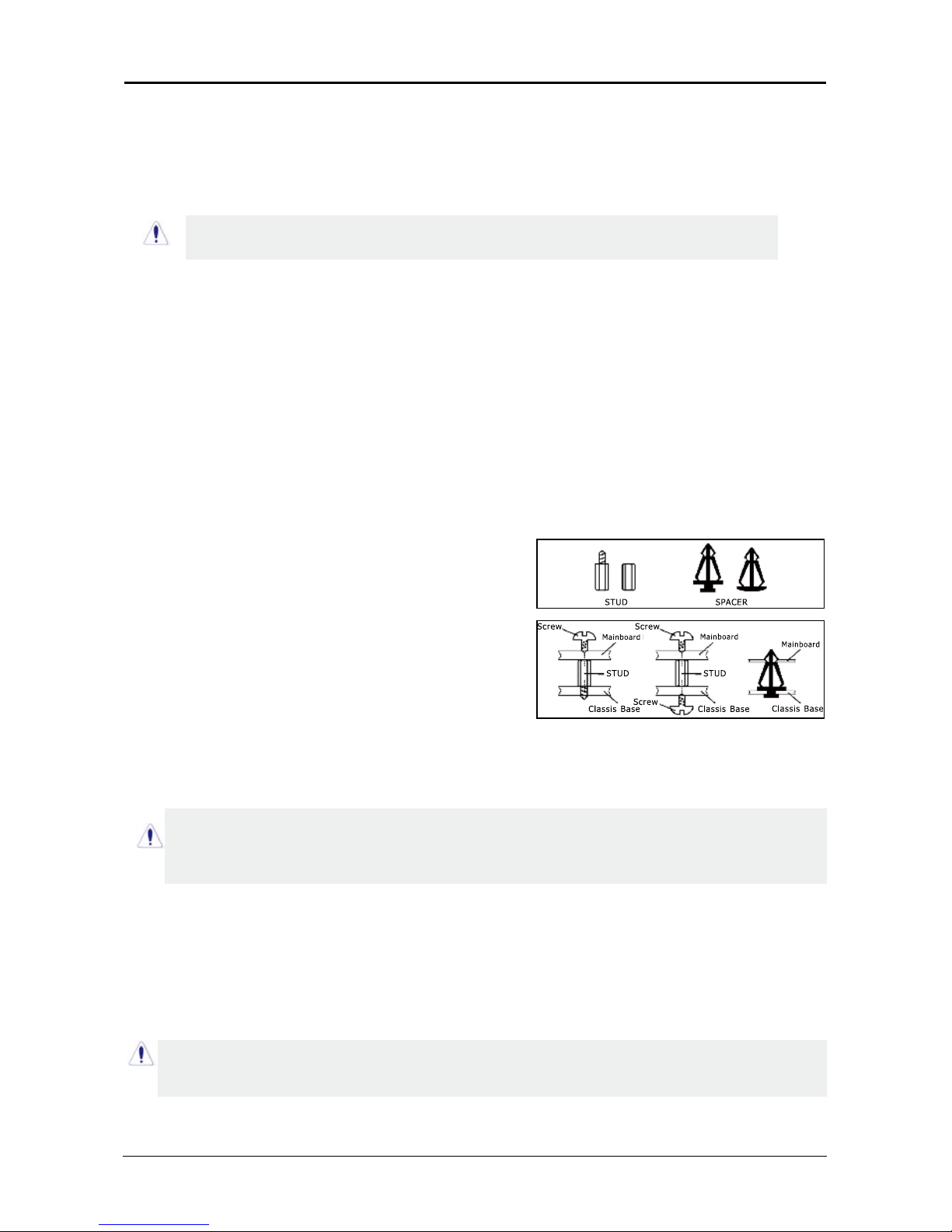
2.2 Installing Mainboard ............................................................................................................ 9
2.3 Installation of the CPU and CPU Cooler................................................................................
10
2.3.1 Installation of the CPU ............................................................................................................ 10
2.3.2 Installation of the CPU Cooler .................................................................................................. 10
2.4 Installation of Memory Modules............................................................................................
11
2.5 Connecting Peripheral Devices............................................................................................. 12
2.5.1 Floppy and IDE Disk Drive Connectors ......................................................................................
12
2.5.2 Serial ATA Connectors .............................................................................................................
12
2.5.3 PCI and PCI Express slots ........................................................................................................
12
Chapter 3 Jumpers & Headers Setup .................................................................... 13
3.1 Checking Jumper Settings ..................................................................................................
13
3.2 CMOS Memory Clearing Header ..........................................................................................
13
3.3 Keyboard Power Function ................................................................................................... 13
3.4 FAN Power Connectors ....................................................................................................... 14
3.5 Front Panel Switches & Indicators Headers .........................................................................
.
14
3.6 Additional USB Port Headers ..............................................................................................
.
15
3.7 Front Panel Audio Connection Header...................................................................................
.
15
3.8 Serial Port Header ..............................................................................................................
1
6
3.9 IR Connection Header ........................................................................................................ 16
3.10 Internal Audio Connectors ................................................................................................
.
17
3.11 ATX Power Input Connectors ............................................................................................
.
17
Chapter 4 BIOS Setup Utility ................................................................................. 18
4.1 About BIOS Setup ............................................................................................................. 18
4.2 To Run BIOS Setup ...........................................................................................................
18
4.3 About CMOS...................................................................................................................... 18
4.4 The POST (Power On Self Test)........................................................................................... 18
4.5 BIOS Setup — CMOS Setup Utility.....................................................................................
..
19
4.5.1 CMOS Setup Utility .............................................................................................................
.
..
19
4.5.2 Control Keys ........................................................................................................................
20
4.5.3 Standard BIOS Features .......................................................................................................
21
4.5.4 Advanced BIOS Features .......................................................................................................
22
4.5.5 Advanced Chipset Features ....................................................................................................
23
4.5.6 PCI/PNP Resource Management............................................................................................
...
24
4.5.7 Boot conguration Features..................................................................................................
...
25
4.5.8 Power Management Features ................................................................................................
. 25
4.5.9 BIOS Security Features .........................................................................................................
.
26
4.5.10 Load Optimized Defaults.... ..............................................................................................
....
27
4.5.11 Load FailSafe Defaults ......................................................................................................... 27
4.5.12 Discard Changes..................................................................................................................
27
4.5.13 Save Changes and Exit......................................................................................................... 28
4.5.14 Discard Changes and Exit.....................................................................................................
28
Chapter 5 Driver Installation ................................................................................
29
APPENDIX 1 .............................................................................................................
31

- 3 -
G31 Series User's Manual
Chapter 1 Introduction
1.1 Package Checklist
Thank you for choosing our product.
Please check the following packing and accessories, if there is any broken or part missing,
please contact with your franchiser.
• HDD Cable X 1
• Serial ATA Cable X 1
• Rear I/O Panel X 1
• User's Manual X 1
• Driver/Utility CD X 1
• Serial ATA Power Cable X 1
• FDD Cable X 1
The items listed above are for reference only, and are subject to change without notice.

- 4 -
G31 Series User's Manual
1.2 Specications-1 (for JW-IG31-MX)
CPU
- LGA775 socket for Intel®Core™2 Extreme/ Core™2 Quad/ Core™
2 Duo/ Pentium®Dual Core/ Pentium®D/Pentium®4 (800MHz
FSB)/ Celeron® (Conroe-L) Processors
- FSB 1333MHZ/1066MHz/800MHz/
- Hyper Threading Technology
Main Chipset - Based on G31 + ICH7
- ICH7: Intel FW82801GB
Graphics - Intel Graphics Media Accelerator 3100
Main Memory
- 2 x 240-pin DIMM slots support
- Maximum memory capacity up to 4GB
- Supports Dual Channel DDRII 667/800MHz
BIOS
- Supports Plug&Play
- Supports BIOS ROM Write Protect
- Supports Advanced Power Management ACPI,STR (S3 Optional)
- Supports 1x SYS FAN, 1x CPU FAN
- CPU temperature, Fan speed, System Voltage monitoring
I/O Chipset - Onboard Winbond W83627
Integrated Ports
- 1 x PS/2 Keyboard port
- 1 x PS/2 Mouse port
- 1 x VGA port
- 1 x Debug LED (Optional)
- 1 x SPDIF IN, 1 x SPDIF Out port (Optional)
- 1 x RJ45 port
- 8 x USB 2.0 ports, USB 1.1 is compliant
- 1 x eSATA port
- 1 x IR port (optional)
- 4 x SATA ports by ICH7 , Maximum Speed to 3GB/s
- 1 x IDE connector, 2 x IDE devices could be connected,
Supports ATA 66/100
- 1 x Floppy Drive, supports 360K/720K/1.2M/1.44M/2.88M oppy disk
Sound
- Onboard ALC883 Chipset
- Supports 6/8 channel HD Audio,24 bit Audio Codec
- Positioning Audio Support A3D, I3DL2
- Front Panel Jumper, provides stereo MIC port on front panel
Onboard LAN - Onboard Marwell 88E8056
Expansion Slots
- 1 x PCI Express x16 slot
- 2 x PCI slots
- Support PCI Bus interface v2.2 compliant
Form Factor - Mirco ATX (208*243.8 mm)

- 5 -
G31 Series User's Manual
1.2 Specications-2 (for JW-IG31-AR/CF)
CPU
- LGA775 socket for Intel®Core™2 Extreme/ Core™2 Quad/ Core™
2 Duo/ Pentium®Dual Core/ Pentium®D/Pentium®4 (800MHz
FSB)/ Celeron® (Conroe-L) Processors
- FSB 1333MHZ/1066MHz/800MHz/
- Hyper Threading Technology
Main Chipset - Based on G31 + ICH7
- ICH7: Intel FW82801GB
Graphics - Intel Graphics Media Accelerator 3100
Main Memory
- 2 x 240-pin DIMM slots support
- Maximum memory capacity up to 4GB
- Supports Dual Channel DDRII 667/800MHz
BIOS
- Supports Plug&Play
- Supports BIOS ROM Write Protect
- Supports Advanced Power Management ACPI,STR (S3 Function)
- Supports 2x SYS FAN, 1x CPU FAN
- CPU temperature, Fan speed, System Voltage monitoring
I/O Chipset - Onboard Winbond W83627
Integrated Ports
- 1 x PS/2 Keyboard port
- 1 x PS/2 Mouse port
- 1 x VGA port
- 1 x Debug LED (Optional)
- 1 x SPDIF IN/Out port (Optional)
- 1 x RJ45 port
- 8 x USB 2.0 ports, USB 1.1 is compliant
- 1 x eSATA port
- 1 x IR port (optional)
- 4 x SATA ports by ICH7, Maximum Speed to 3GB/s
- 1 x IDE connector, 2 x IDE devices could be connected,
Supports ATA 66/100
- 1 x Floppy Drive, supports 360K/720K/1.2M/1.44M/2.88M oppy disk
Sound
- Onboard ALC888 Chipset
- Supports 6/8 channel HD Audio, 24 bit Audio Codec
- Positioning Audio Support A3D, I3DL2
- Front Panel Jumper, provides stereo MIC port on front panel
Onboard LAN - Onboard Realtek RTL8810S/SC
Expansion Slots
- 2 x PCI Express x16 slot (Including one x16 slot, another running at
x4 speed)
- 1 x PCI Express x1 slot
- 3 x PCI slots
- Support PCI Bus interface v2.2 compliant
Form Factor - ATX (199.9*304.8 mm)

- 6 -
G31 Series User's Manual
1.3 Mainboard Layout - 1 (PCB Layout for JW-IG31-MX)
(This picture is only for reference)
(Optional)

- 7 -
G31 Series User's Manual
1.3 Mainboard Layout - 2 (PCB Layout for JW-IG31-AR/CF)
(This picture is only for reference)
1
SFAN2
SFAN1
VGA
JDDR1

- 8 -
G31 Series User's Manual
1.4 Connecting Rear Panel I/O Devices
The rear I/O part of these mainboard provides the following I/O ports:
(This picture is only for reference)
• PS/2 Mouse: Connect to PS/2 mouse.
• PS/2 Keyboard: Connect to PS/2 keyboard.
• Debug LED: Display error code. (please reference attached 1)
• VGA: Connect to monitor input.
• eSATA: Connect to peripherial SATA devices.The peripherial SATA devices must connect
inside SATA connectors.
• SPDIF OUT: Connect to digital audio device.
• LAN: Connect to Local Area Network.
• USB: Connect to USB devices such as scanner, digital speakers, monitor, mouse, keyboard,
hub, digital camera, joystick etc.
• AUDIO1:
Cen./Sub. (Center / Subwoofer): Connect to the center and subwoofer channel in the 7.1
channel audio system.
R.L./R.R. (Rear Left / Rear Right): Connect to the rear left and rear right channel in the 7.1
channel audio system.
S.L./S.R. (Surround Left / Surround Right): Connect to the surround left and surround right
channel in the 7.1 channel audio system.
Line-In: Connect to the line out from external audio sources.
Line-Out: Connect to the front left and front right channel in the 7.1-channel or regular
2-channel audio system.
Mic-In: Connect to the plug from external microphone.
(Optional)
VGA
(Optional)(Optional)
(Optional)
Debug LED

- 9 -
G31 Series User's Manual
Chapter 2 Hardware Setup
2.1 Choosing a Computer Chassis
• Choose a chassis big enough to install this mainboard.
• As some features for this mainboard are implemented by cabling connectors on the
mainboard to indicators and switches or buttons on the chassis, make sure your chassis
supports all the features required.
• If there is possibility of adopting some more hard drives, make sure your chassis has
sufcient power and space for them.
• Most chassis have alternatives for I/O shield located at the rear panel. Make sure the I/O
shield of the chassis matches the I/O port conguration of this mainboard. You can nd
an I/O shield specically designed for this mainboard in its package.
2.2 Installing Mainboard
Most computer chassis have a base with many mounting holes to allow the mainboard to
be securely attached, and at the same time, prevent the system from short circuits. There
are two ways to attach the mainboard to the
chassis base: (1) with studs, or (2) with spacers.
Basically, the best way to attach the board is with
studs. Only if you are unable to do this should you
attach the board with spacers. Line up the holes on
the board with the mounting holes on the chassis.
If the holes line up and there are screw holes, you
can attach the board with studs. If the holes line
up and there are only slots, you can only attach with
spacers. Take the tip of the spacers and insert them
into the slots. After doing this to all the slots, you can slide the board into position aligned
with slots. After the board has been positioned, check to make sure everything is OK before
putting the chassis back on.
To install this mainboard:
1. Locate all the screw holes on the mainboard and the chassis base.
2. Place all the studs or spacers needed on the chassis base and have them tightened.
3. Face the mainboard’s I/O ports toward the chassis’s rear panel.
4. Line up all the mainboard’s screw holes with those studs or spacers on the chassis.
5. Install the mainboard with screws and have them tightened.
The mainboard and its component layouts illustrated in this chapter were
based mainly on model “
JW-IG31-MX
”, unless specically stated.
Always power off the computer and unplug the AC power cord before adding or removing
any peripheral or component. Failing to do so may cause severe damage to your
mainboard and/or peripherals. Plug in the AC power cord only after you have carefully
checked everything.
To prevent shorting the PCB circuit, please REMOVE the metal studs or spacers if they are
already fastened on the chassis base and are without mounting-holes on the mainboard to
align with.

- 10 -
G31 Series User's Manual
2.3 Installation of the CPU and CPU Cooler
Before installing the CPU, please comply with the following conditions:
1. Please make sure that the mainboard supports the CPU.
2. Please take note of the one indented corner of the CPU. If you install the CPU in the wrong
direction, the CPU will not insert properly. If this occurs, please change the insert direction
of the CPU.
3. Please add an even layer of heat sink paste between the CPU and CPU cooler.
4. Please make sure the CPU cooler is installed on the CPU prior to system use, otherwise
overheating and permanent damage of the CPU may occur.
5. Please set the CPU host frequency in accordance with the processor specications. It is not
recommended that the system bus frequency be set beyond hardware specications since
it does not meet the required standards for the peripherals. If you wish to set the frequen-
cy beyond the proper specications, please do so according to your hardware
specications including the CPU, graphics card, memory, hard drive, etc.
2.3.1 Installation of the CPU
1
2
5
6
6
7
7
8
8
9
10
1. Open the socket lever by
pushing the lever down and
away from the socket (see
Figure 1, 1 and 2).
2. Lift the load plate. Do not
touch the socket contacts
(see Figure 2, 3 and 4)
3 . R e m o ve t h e p l a s t i c
protective socket cover
from the load plate (see
Figure 3, 5). Do not discard
the protective socket cover.
Always replace the socket
cover if the processor is
removed from the socket.
4. Remove the processor
f r o m t h e p r o t e c t i v e
processor cover. Hold the
processor only at the edges,
being careful not to touch
the bottom of the processor
(see Figure 4). Do not
d i s c a r d t h e p r o t e c t i v e
processor cover. Always
replace the processor
back to the package if the
processor is removed from
the socket.
5. Hold the processor with
y o u r t h u m b a n d i n d e x
ngers oriented as shown in
Figure 5. Make sure ngers
align to the socket cutouts
(see Figure 5, 6). Align
notches (see Figure 5, 7)
with the socket see (Figure
5, 8). Lower the processor
straight down without tilting
or sliding the processor in
the socket.
6. Pressing down on the
load plate (Figure 6, 9)
c l o s e a n d e n g a g e t h e
socket lever (Figure 6, 10).
Figure 1
Figure 2
Figure 3
Figure 4
Figure 6
Figure 5

- 11 -
G31 Series User's Manual
2.3.2 Installation of the CPU Cooler
For proper installation, please kindly refer to the instruction manuals of your CPU Cooler.
2.4 Installation of Memory Modules
This mainboard provides two 240-pin DDRII (Double Data Rate) DIMM slots, and supports
Dual Channel Memory Technology. For dual channel conguration, you always need to install
two identical (the same brand, speed, size and chip-type) memory modules in the DDRII
DIMM slots to activate Dual Channel Memory Technology. Otherwise, it will operate at single
channel mode.
To reach the performance of Dual Channel DDR2, the following rules must be obeyed:
For 2-DIMM dual-channel installation:
Populate DIMM modules of the same type and size on slots [DIMM1]+[DIMM2].
To install system memory:
1. Power off the computer and unplug the
AC power cord before installing or
removing memory modules.
2. Locate the DIMM slot on the board.
3. Hold two edges of the DIMM module
carefully, keep away from touching its
connectors.
4. Align the notch key on the module with
the rib on the slot.
5. Firmly press the module into the slots until the ejector tabs at both sides of the slot
automatically snap into the mounting notch. Do not force the DIMM module in with extra
force as the DIMM module only ts in one direction.
6. To remove the DIMM modules, push the two ejector tabs on the slot outward
simultaneously, and then pull out the DIMM module.
Static electricity can damage the electronic components of the computer or optional
boards. Before starting these procedures, ensure that you are discharged of static
electricity by touching a grounded metal object briey.

- 12 -
G31 Series User's Manual
2.5 Connecting Peripheral Devices
2.5.1 Floppy and IDE Disk Drive Connectors
The FDD connector connects up to two oppy drives with a 34-wire, 2-connector oppy
cable.Connect the single end at the longer length of ribbon cable to the FDD on the board,
the two connectors on the other end to the oppy disk drives connector. Generally you need
only one oppy disk drive in your system.
2.5.2 Serial ATA Connectors
Each SATA connector serves as one single channel to connect one SATA device by SATA
cable.
2.5.3 PCI and PCI Express slots
Install PCI Express X16 graphics card into slot “PCIE1”.
Install PCI card into slots “PCI1” or “PCI2” .
Each of the IDE port connects up to two
IDE drives at Ultra ATA 66/100 mode by one
40-pin, 80-conductor,and 3-connector Ultra
ATA/66 ribbon cables.
Connect the single end (blue connector) at the
longer length of ribbon cable to the IDE port of
this board, the other two ends (gray and black
connector) at the shorter length of the ribbon
cable to the connectors of your hard drives.
Make sure to congure the “Master” and “Slave” relation
before connecting two drives by one single ribbon cable.
The red line on the ribbon cable must be aligned with
pin-1 on both the IDE port and the hard-drive connector.
The red line on the ribbon cable must be aligned with pin-1 on both the FDD port and the oppy connector.
• eSATA: Connect to peripherial SATA devices.The
peripherial SATA devices must connect inside
SATA connectors. (Optional)
SATA1SATA4
SATA2SATA3

- 13 -
G31 Series User's Manual
Chapter 3 Jumpers & Headers Setup
3.1 Checking Jumper Settings
• For a 2-pin jumper, plug the jumper cap on both
pins will make it CLOSE (SHORT). Remove the
jumper cap, or plug it on either pin (reserved for
future use) will leave it at OPEN position.
• For 3-pin jumper, pin 1~2 or pin 2~3 can be
shorted by plugging the jumper cap in.
How to identify the PIN1 jumpers?
Please check the mainboard carefully, the PIN1
is marked by "1" or white thick line.
3.2 CMOS Memory Clearing Header
The time to clear the CMOS memory occurs when (a)
the CMOS data becomes corrupted, (b) you forgot
the supervisor or user password preset in the BIOS
menu, (c) you are unable to boot-up the system
because the CPU ratio/clock was incorrectly set in the
BIOS menu, or (d) whenever there is modication on
the CPU or memory modules.
This header uses a jumper cap to clear the CMOS
memory and have it recongured to the default
values stored in BIOS.
• Pins 1 and 2 shorted
(Default): Normal
operation.
• Pins 2 and 3 shorted:
Clear CMOS memory.
To clear the CMOS memory and load in the default values:
1. Power off the system.
2. Set pin 2 and pin 3 shorted by the jumper cap. Wait for a few seconds. Set the jumper
cap back to its default settings --- pin 1 and pin 2 shorted.
3. Power on the system.
4. For incorrect CPU ratio/clock settings in the BIOS, press <Del> key to enter the BIOS
setup menu right after powering on system.
5. Set the CPU operating speed back to its default or an appropriate value.
6. Save and exit the BIOS setup menu.
3.3 Keyboard Power Function(JKB)
Pin 1-2 short: Disabled power on by keyboard
Pin 2-3 short: Support power on by keyboard
JKB:

- 14 -
G31 Series User's Manual
3.4 FAN Power Connectors
These connectors each provide power to the cooling fans installed in your system.
CFAN or CFAN1: CPU Fan Power Connector
SYSFAN1: System Fan Power Connector
SYSFAN2: System Fan Power Connector (Optional)
3.5 Front Panel Switches & Indicators Headers
1
SPEAKER
HDD_LED (Hard Driver LED Header)
Connect the HDD LED cable to these PINs, in order to see the HDD status
RESET (Reset Control)
This connector connects to the case-mounted reset switch for rebooting your computer
without having to turn off your power switch. This is a preferred method of rebooting in
order to prolong the lift of the system’s power supply.
PWR-ON (Power Button)
This connector connects to the case-mounted power switch to power ON/OFF the system.
SPEAKER (Speaker)
This 4-pin connector connects to the case-mounted speaker. You should follow the
instruction of the speaker cable.
These fan connectors are not jumpers. DO NOT place
jumper caps on these connectors.
JDDR1 DDR Voltage
1-2 Default
2-3 1.9V
CFAN or CFAN1
SFAN1
SFAN2

- 15 -
G31 Series User's Manual
Pin Pin Assignment Pin Pin Assignment
1VCC 2VCC
3Data 0- 4Data 0-
5 Data 0+ 6 Data 0+
7 Ground 8 Ground
9 No Pin 10 NC
HD Audio:
Pin No. Denition
1 MIC2_L
2 AGND
3 MIC2_R
4 NC
5 OUT_R
6 MIC2_JD
7 SENSE
8 No Pin
9 OUT_L
10 OUT_JD
3.6 Additional USB Port Headers
3.7 Front Panel Audio Connection Header
FUSB1 FUSB2
,
1
2
9
10

- 16 -
G31 Series User's Manual
3.8 Serial Port Header
This JCOM1 header supports a serial port module.
Pin Pin Assignment Pin Pin Assignment
1 DCD 2 RXD
3 TXD 4 DTR
5 GND 6 DSR
7 RTS 8 CTS
9 RI
3.9 IR Connection Header
Connect the IrDA cable (if available) to this IR connector.
Pin No. Denition
1 VCC
2 NC
3 IRRX
4 GND
5 IRTX

- 17 -
G31 Series User's Manual
3.10 Internal Audio Connectors
Connect CD-ROM or DVD-ROM audio out to the connector.
3.11 ATX Power Input Connectors
This mainboard provides two power connectors to connect power supplier.
Pin No. Denition
1 CD-L
2 GND
3 GND
4 CD-R
There are two ATX 12V
connectors according
to different Model,
one is 4Pin,another
is 8pin, followin
pictures are for
reference.
1.ATX 4Pin
2.ATX 8Pin

- 18 -
G31 Series User's Manual
Chapter 4 BIOS Setup Utility
BIOS stands for Basic Input and Output System. It was once called ROM BIOS when it was
stored in a Read-Only Memory (ROM) chip. Now manufacturers would like to store BIOS in
EEPROM which means Electrically Erasable Programmable Memory. BIOS used in this series
of mainboard is stored in EEPROM, and is the first program to run when you turn on your
computer.
BIOS performs the following functions:
1. Initializing and testing hardware in your computer (a process called "POST", for Power On
Self Test).
2. Loading and running your operating system.
3. Helping your operating system and application programs manage your PC hardware by
means of a set of routines called BIOS Run-Time Service.
4.1 About BIOS Setup
BIOS Setup is an interactive BIOS program that you need to run when:
1. Changing the hardware of your system. (For example: installing a new Hard Disk etc.)
2. Modifying the behavior of your computer. (For example: changing the system time or date,
or turning special features on or off etc.)
3. Enhancing your computer's behavior. (For example: speeding up performance by turning
on shadowing or cache)
4.2 To Run BIOS Setup
First access BIOS setup menu by pressing <F1> key after “POST” is complete (before OS is
loaded). After the rst BIOS be setupped(or loaded default values) and save, the <DEL> key
will be pressed if you will enter BIOS setup menu.
4.3 About CMOS
CMOS is the memory maintained by a battery. CMOS is used to store the BIOS settings you
have selected in BIOS Setup. CMOS also maintains the internal clock. Every time you turn
on your computer, the BIOS Looks into CMOS for the settings you have selected and
congures your computer accordingly. If the battery runs out of power, the CMOS data will
be lost and POST will issue a “CMOS invalid” or “CMOS checksum invalid” message. If this
happens, you have to replace the battery and check and congure the BIOS Setup for the
new start.
4.4 The POST (Power On Self Test)
POST is an acronym for Power On Self Test. This program will test all things the BIOS does
before the operating system is started. Each of POST routines is assigned a POST code, a
unique number which is sent to I/O port 080h before the routine is executed.

- 19 -
G31 Series User's Manual
CMOS Setup Utility - Copyright (C) 1985-2004,American Megatrends,Inc.
►
Standard BIOS Features
►
Advanced BIOS Features
►
Advanced Chipset Features
►
PCI/PNP Resource Management
►
Boot Configuration Features
►
Power Management Features
►
BIOS Security Features
Load Optimal Defaults
Load Failsafe Defaults
Discard Changes
Save Changes and Exit
Discard Changes and Exit
↑↓
→←
:Move Enter:Select +/-/:Value F10:Save ESC:Exit F1:General Help
F7:Previous Values F8:Fail-Safe Defaults F9:Optimized Defaults
Configure Time and Date. Display System Information...
v0.258 (C)Copyright 1985-2005,American Megatrends, Inc.
4.5 BIOS Setup — CMOS Setup Utility
4.5.1 CMOS Setup Utility
After powering up the system, the BIOS message appears on the screen,when the rst time
or when CMOS setting wrong, there is following message appears on the screen , but if
the rst BIOS be setuped(or loaded default values) and save, the <DEL> key will be
pressed if you will enter BIOS setup menu.
If this message disappears before you respond, restart the system by pressing <Ctrl> +
<Alt>+ <Del> keys, or by pressing the reset button on computer chassis. Only when these
two methods should be fail that you restart the system by powering it off and then back on.
After pressing <F1> or <Del> key, the main menu appears.
Press F1 to Run SETUP
• Standard BIOS Features
This setup page includes all the items in standard compatible BIOS.
• Advanced BIOS Features
This setup page includes all the items of AMI special enhanced features.
• Advanced Chipset Features
This setup page includes the chipset features.
• PCI/PNP Resource Management
This setup page includes all the congurations of PCI & PNP resources.
• Boot Conguration Features
This setup page includes the congurations of Boot Settings.
• Power Management Features
This setup page includes all the items of Green function features.
• In order to increase system stability and performance, our engineering staff is
constantly improving the BIOS menu. The BIOS setup screens and descriptions
illustrated in this manual are for your reference only, and may not completely
match with what you see on your screen.
• Do not change the BIOS parameters unless you fully understand its function.
►
Standard BIOS Features
Table of contents
Other J&W Motherboard manuals

J&W
J&W Intel P43 Series User manual

J&W
J&W JW-A780LM-D3 User manual

J&W
J&W JW-A880GMT-EXTREME User manual

J&W
J&W Intel P43 Series User manual

J&W
J&W JW-A740GM-D2 User manual

J&W
J&W nVIDIA MCP78 Series User manual

J&W
J&W JW-A880GM-FUSION User manual

J&W
J&W X48 Series User manual

J&W
J&W ATI 690G User manual

J&W
J&W JW-A870T-UC3 User manual

J&W
J&W nVIDIA NF520LE User manual

J&W
J&W Minix780G Series User manual

J&W
J&W JW-A75GM-USB3 User manual

J&W
J&W JW-H61M-L3 User manual

J&W
J&W JW-N7AS-HD User manual

J&W
J&W Z77A-ProX User manual

J&W
J&W nVIDIA N61P User manual

J&W
J&W JW-D525M-GT User manual

J&W
J&W AMD 790GX User manual

J&W
J&W JW-H61M-D3 User manual