J&W Minix780G Series User manual

Rev: 1.00, July 2008
P/N: 80ECM78010
User's Manual
Minix780G Series
Socket AM2/AM2+ Processor Mainboard
Website: http://www.jwele.com

Disclaimer
The intellectual property of this manual belongs to our company. The ownership of all of the
products, including accessories and software etc. belong to our company. No one is permitted to
copy, change, or translate without our written permission.
We compiled this manual based on our careful attitude, but we can not guarantee the accuracy of
the contents. This manual is purely technical documentation, without any hint or other meanings,
and we won't commit users' misunderstanding of the typesetting error.
Our products are in continuous improvement and updating, Therefore, we retain the right that we
won't give notice to the users in future.
Copyright
All of the trademark in this manual belong to their own registered company.
All of the products name is only for identification, its title belongs to its manufacturer or brand
owner.

Table of Contents
Chapter 1 Introduction ............................................................................................ 4
1.1 Package Checklist ................................................................................................................4
6SHFL¿FDWLRQV ......................................................................................................................5
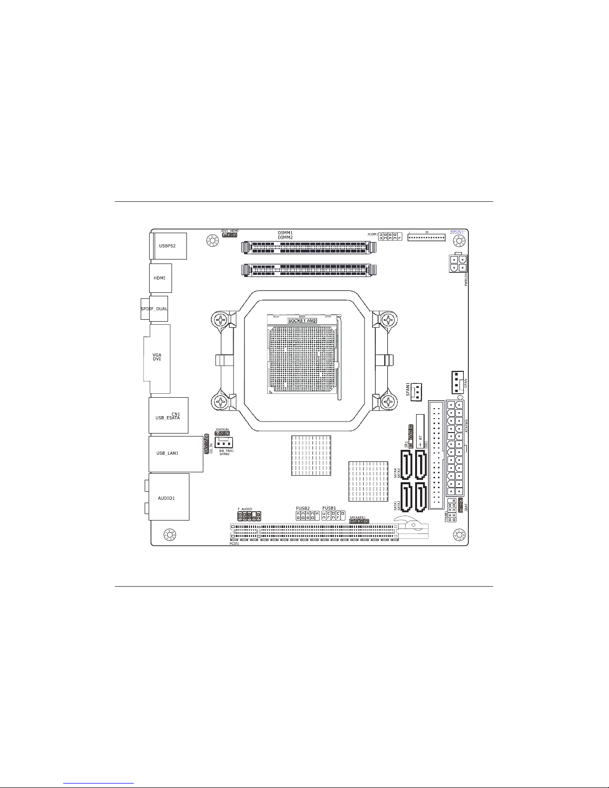
1.3 Mainboard Layout................................................................................................................6
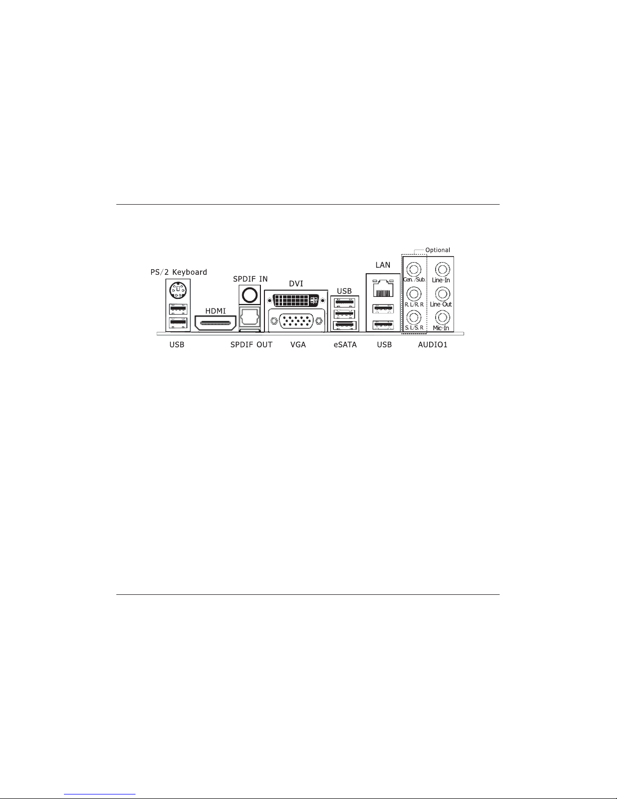
1.4 Connecting Rear Panel I/O Devices .......................................................................................7
Chapter 2 Hardware Setup....................................................................................... 8
2.1 Choosing a Computer Chassis...............................................................................................8
2.2 Installing Mainboard ............................................................................................................8
2.3 Installation of the CPU and CPU Cooler .................................................................................9
2.3.1 Installation of the CPU ...................................................................................................9
2.3.2 Installation of the CPU Cooler....................................................................................... 10
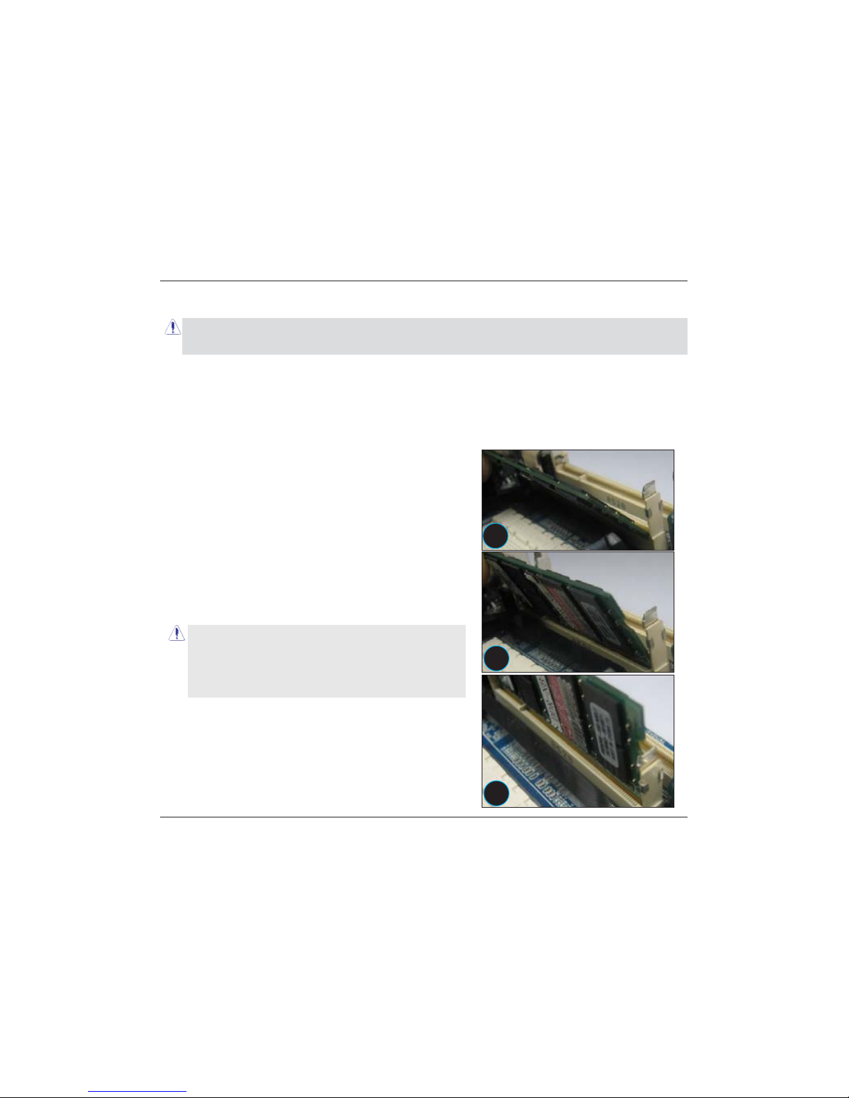
2.4 Installation of Memory Modules .......................................................................................... 10
2.5 Connecting Peripheral Devices ............................................................................................ 11
2.5.1 IDE Disk Drive Connectors............................................................................................ 11
2.5.2 Serial ATA Connectors .................................................................................................. 11
2.5.3 PCI Express slots ......................................................................................................... 11
Chapter 3 Jumpers & Headers Setup .......................................................................12
Chapter 4 BIOS Setup Utility ...................................................................................17
4.1 About BIOS Setup.............................................................................................................. 17
4.2 To Run BIOS Setup ............................................................................................................ 17
4.3 About CMOS...................................................................................................................... 17
4.4 The POST (Power On Self Test) .......................................................................................... 17
4.5 BIOS Setup — CMOS Setup Utility....................................................................................... 18
4.5.1 CMOS Setup Utility....................................................................................................... 18
4.5.2 Control Keys................................................................................................................ 20
4.5.3 Advanced Setting......................................................................................................... 21
4.5.4 PCIPnP Setting ............................................................................................................25
4.5.5 Boot Setting ................................................................................................................ 26
4.5.6 Security Setting ........................................................................................................... 28
4.5.7 JUSTw00T! Setting....................................................................................................... 29
4.5.8 Power Setting.............................................................................................................. 33
4.5.9 Exit Setting ................................................................................................................. 35
Chapter 5 Driver Installation ...................................................................................39
Ё᭛⠜ᴀ䇈ᯢк .....................................................................................................41

Minix780G Series User's Manual
- 4 -
Chapter 1 Introduction
1.1 Package Checklist
Thank you for choosing our product.
Please check the following packing and accessories, if there is any broken or part missing,
please contact with your franchiser.
• HDD Cable X 1
• Rear I/O Panel X 1
• User's Manual X 1
• Driver/Utility CD X 1
• Serial ATA Signal Cable X 1
• Serial ATA Power Cable X 1 (Optional)
The items listed above are for reference only, and are subject to change without notice.

Minix780G Series User's Manual
- 5 -
6SHFL¿FDWLRQV
CPU
- Supports AMD®Socket AM2+ / AM2 processors:
- AMD Phenom™ / Athlon™ 64 FX / Athlon™ 64 X2 Dual Core / Athlon™ 64 /
Sempron™
- Hyper Transport Bus 5200/2000 MT/s (HT 3.0/1.0)
- Note: The board can not support 125W TDP processors. For details , please
refer to the CPU support list on our homepage.
Main Chipset - AMD®780G + SB700
- Built in Radeon™ HD 3200 Graphics, DirectX®10 Ready
Main Memory
- Supports 2 x 1.8V DDR2 SODIMM sockets supporting up to 4 GB of
system memory
- Supports Dual channel memory architecture
- Onboard side-port DDR2 memory
- Supports for DDR2 1066MHz/800MHz/667MHz memory modules
BIOS
- AMI BIOS, supports Plug&Play
- Supports BIOS ROM Write Protect
- Supports Advanced Power Management ACPI,STR
- CPU temperature, Fan speed, System Voltage monitoring
Integrated Ports
- 1 x PS/2 Keyboard port
- 1 x DVI port
- 1 x HDMI port
- 1 x VGA port
- 1 x RJ45 port
- 1 x eSATA port
- 1 x COM port
- 1 x IR port
- 10 x USB 2.0 ports, USB 1.1 is compliant
- 4 x SATA ports , Maximum Speed to 3GB/s,support for SATA RAID 0,1,10
- 1 x IDE connector, 2 x IDE devices could be connected,
Supports ATA 133/100/66/33
Sound - Onboard 6-channel/8-channel HD Audio Codec (Optional)
- Front Panel Jumper, provides stereo MIC port on front panel
Onboard LAN - Onboard 10/100/1000Mbps compatible LAN (Optional)
Expansion Slots - 1 x PCI Express x4 slot(PCI Express 2.0)
Form Factor Mini ITX (170mm*170mm)
Remark - 1066 MHz memory support is dependent on the CPU being used

Minix780G Series User's Manual
- 6 -
1.3 Mainboard Layout
(This picture is only for reference)

Minix780G Series User's Manual
- 7 -
1.4 Connecting Rear Panel I/O Devices
The rear I/O part of these mainboard provides the following I/O ports:
(This picture is only for reference)
• PS/2 Keyboard: Connect to PS/2 keyboard.
• HDMI:Connects to multimedia devices of HDMI protocol.
• SPDIF IN:This connector provides an S/PDIF-IN connection.
• SPDIF OUT:Connects to digital audio device.
• DVI: Connects to monitor input.
• VGA: Connects to monitor input.
• eSATA: Connect to peripherial SATA devices.
• LAN: Connects to Local Area Network.
• USB: Connects to USB devices such as scanner, digital speakers, monitor, mouse, keyboard,
hub, digital camera, joystick etc.
• AUDIO1:
Cen./Sub. (Center / Subwoofer): Connect to the center and subwoofer channel in the 7.1
channel audio system.
R.L./R.R. (Rear Left / Rear Right): Connect to the rear left and rear right channel in the 7.1
channel audio system.
S.L./S.R. (Surround Left / Surround Right): Connect to the surround left and surround right
channel in the 7.1 channel audio system.
Line-In: Connects to the line out from external audio sources.
Line-Out: Connects to the front left and front right channel in the 7.1-channel or regular
2-channel audio system.
Mic-In: Connects to the plug from external microphone.

Minix780G Series User's Manual
- 8 -
Chapter 2 Hardware Setup
2.1 Choosing a Computer Chassis
• Choose a chassis big enough to install this mainboard.
• As some features for this mainboard are implemented by cabling connectors on the mainboard
to indicators and switches or buttons on the chassis, make sure your chassis supports all the
features required.
,IWKHUHLVSRVVLELOLW\RIDGRSWLQJVRPHPRUHKDUGGULYHVPDNHVXUH\RXUFKDVVLVKDVVXI¿FLHQW
power and space for them.
• Most chassis have alternatives for I/O shield located at the rear panel. Make sure the I/O shield
RIWKHFKDVVLVPDWFKHVWKH,2SRUWFRQ¿JXUDWLRQRIWKLVPDLQERDUG<RXFDQ¿QG an I/O shield
VSHFL¿FDOO\GHVLJQHGIRUWKLVPDLQERDUGLQLWVSDFNDJH
2.2 Installing Mainboard
Most computer chassis have a base with many mounting holes to allow the mainboard to be
securely attached, and at the same time, prevent
the system from short circuits. There are two ways
to attach the mainboard to the chassis base:
(1)with studs, or (2) with spacers.
Basically, the best way to attach the board is with
studs. Only if you are unable to do this should you
attach the board with spacers. Line up the holes on
the board with the mounting holes on the chassis.
If the holes line up and there are screw holes, you
can attach the board with studs. If the holes line
up and there are only slots, you can only attach with
spacers. Take the tip of the spacers and insert them into the slots. After doing this to all the slots,
you can slide the board into position aligned with slots. After the board has been positioned,
check to make sure everything is OK before putting the chassis back on.
To install this mainboard:
1. Locate all the screw holes on the mainboard and the chassis base.
2. Place all the studs or spacers needed on the chassis base and have them tightened.
3. Face the mainboard’s I/O ports toward the chassis’s rear panel.
4. Line up all the mainboard’s screw holes with those studs or spacers on the chassis.
5. Install the mainboard with screws and have them tightened.

Minix780G Series User's Manual
- 9 -
2.3 Installation of the CPU and CPU Cooler
Before installing the CPU, please comply with the following conditions:
1. Please make sure that the mainboard supports the CPU.
2. Please take note of the one indented corner of the CPU. If you install the CPU in the wrong
direction, the CPU will not insert properly. If this occurs, please change the insert direction of
the CPU.
3. Please add an even layer of heat sink paste between the CPU and CPU cooler.
4. Please make sure the CPU cooler is installed on the CPU prior to system use, otherwise
overheating and permanent damage of the CPU may occur.
3OHDVHVHWWKH&38KRVWIUHTXHQF\LQDFFRUGDQFHZLWKWKHSURFHVVRUVSHFL¿FDWLRQV,WLVQRW
UHFRPPHQGHGWKDWWKHV\VWHPEXVIUHTXHQF\EHVHWEH\RQGKDUGZDUHVSHFL¿FDWLRQVVLQFHLW
does not meet the required standards for the peripherals. If you wish to set the frequency
EH\RQGWKHSURSHUVSHFL¿FDWLRQVSOHDVHGRVRDFFRUGLQJWR\RXUKDUGZDUHVSHFL¿FDWLRQV
including the CPU, graphics card, memory, hard drive, etc.
2.3.1 Installation of the CPU
1. Unlock the socket by pressing the
lever sideways, then lift it up to a 90
o
.
2. Position the CPU above the socket such that
the CPU corner with the gold triangle matches
the socket corner with a small triangle.
3. Carefully insert the CPU into the socket until it
¿WVSODFH
4. When the CPU is in
place, push down the
socket lever to secure
the CPU.
The lever clicks on the
side tab to indicate that
it is locked.
Figure 1
Figure 2
Figure 3

Minix780G Series User's Manual
- 10 -
2.3.2 Installation of the CPU Cooler
For proper installation, please kindly refer to the instruction manuals of your CPU Cooler.
2.4 Installation of Memory Modules
This mainboard provides two 200-pin DDRII (Double Data Rate) SODIMM slots and supports
'XDO&KDQQHO0HPRU\7HFKQRORJ\)RUGXDOFKDQQHOFRQ¿JXUDWLRQ\RXDOZD\VQHHGWRLQVWDOOWZR
identical (the same brand, speed, size and chip-type) memory modules in the DDRII DIMM slots
to activate Dual Channel Memory Technology. Otherwise, it will operate at single channel mode.
To install system memory:
1. Power off the computer and unplug the
AC power cord before installing or
removing memory modules.
2. Locate the DIMM slot on the board.
3. Insert the SODIMM module at a 45 degree
angle.
4. Push the SODIMM module back towards the
board until the clips lock the module in place.
5. To remove the DIMM modules, push the two
ejector tabs on the slot outward simultaneously,
and then pull out the DIMM module.
Static electricity can damage the electronic
components of the computer or optional boards.
Before starting these procedures, ensure that you
are discharged of static electricity by touching a
JURXQGHGPHWDOREMHFWEULHÀ\
1
2
3
We suggest there should be active cooling to the chipset area in order to let the motherboard
IXQFWLRQSURSHUO\FRPSOHWHO\ HQFORVHGV\VWHPHQYLURQPHQW ZLWKRXWDGHTXDWHDLU ÀRZZLOOUHVXOW
in chipset overheat, which is not recommended.

Minix780G Series User's Manual
- 11 -
2.5 Connecting Peripheral Devices
2.5.1 IDE Disk Drive Connectors
2.5.2 Serial ATA Connectors
Each SATA connector serves as one single channel to connect one SATA device by SATA cable.
2.5.3 PCI Express slots
PCIE1 is for PCI Express X4 slot.
Each of the IDE port connects up to two IDE
drives at Ultra ATA 133/100/66/33 mode by
one 40-pin, 80-conductor,and 3-connector Ultra
ATA/66 ribbon cables.
Connect the single end (blue connector) at the
longer length of ribbon cable to the IDE port of
this board, the other two ends (gray and black
connector) at the shorter length of the ribbon
cable to the connectors of your hard drives.
0DNHVXUHWRFRQ¿JXUHWKH³0DVWHU´DQG³6ODYH´UHODWLRQ
before connecting two drives by one single ribbon cable.
The red line on the ribbon cable must be aligned with
pin-1 on both the IDE port and the hard-drive connector.

Minix780G Series User's Manual
- 12 -
Chapter 3 Jumpers & Headers Setup
Quick Components Guide
NO. Layout Page NO. No. Layout Page NO.
1 JBAT 13 9 FUSB1/FUSB2 15
2 JDVI_HDMI 13 10 SPEAKER1 15
3 J5VDUAL 14 11 FPANEL 15
4CFAN 14 12 IR1 15
5 SFAN1 14 13 JCOM1 16
6 SFAN2 14 14 J1 16
7 CD_IN 14 15 PWR12V 16
8 F_AUDIO 14 16 ATXPWR 16
1
2
3
4
5
6
7
8
910
11
12
13 14
15
16

Minix780G Series User's Manual
- 13 -
Normal
(Default
Clear CMOS
JBAT or CLR CMOS1 B
123
123
Checking Jumper Settings
• For a 2-pin jumper, plug the jumper cap on both pins will make it CLOSE (SHORT). Remove the
jumper cap, or plug it on either pin (reserved for future use) will leave it at OPEN position.
• For 3-pin jumper, pin 1~2 or pin 2~3 can be shorted by plugging the jumper cap in.
How to identify the PIN1 jumpers?
Please check the mainboard carefully, the PIN1 is marked by "1" or white thick line.
1-JBAT(CMOS Memory Clearing Header)
The time to clear the CMOS memory occurs when (a) the CMOS data becomes corrupted, (b) you
forgot the supervisor or user password preset in the BIOS menu, (c) you are unable to boot-up
the system because the CPU ratio/clock was incorrectly set in the BIOS menu, or (d) whenever
WKHUHLVPRGL¿FDWLRQRQWKH&38RUPHPRU\PRGXOHV
This header uses a jumper cap to clear the CMOS
PHPRU\DQGKDYHLWUHFRQ¿JXUHGWRWKHGHIDXOWYDOXHV
stored in BIOS.
• Pins 1 and 2 shorted (Default): Normal operation.
• Pins 2 and 3 shorted: Clear CMOS memory.
2-JDVI_HDMI(DVI/HDMI Setting Header)
1-2˄Default˅Auto While JDVI_HDMI jumper be shorted
#pin 1-2, it will auto detect HDMI or
DVI device, but if some DVI or HDMI
device cann't be detected, please be
shorted #pin 2-3.
2-3 DVI/HDMI EN

Minix780G Series User's Manual
- 14 -
3-J5VDUAL(5VDUAL Setting Header)
1-2˄Default˅Enable 2-3 pin can not support the
keyboard post function,need to
set 1~2 pin enable the function.
2-3 Disable
4/5/6-CFAN/SFAN1/SFAN2(Fan Power Connectors)
CFAN˖
Pin No. 'H¿QLWLRQ
1 GND
2 +12V
3 RPM
4 Control
SFAN1/SFAN2˖
Pin No. 'H¿QLWLRQ
1 GND
2 +12V
3 RPM
7-CD_IN(Internal Audio Connectors)
8-F_AUDIO(Front Panel Audio Connection Header)
Pin No. 'H¿QLWLRQ Pin No. 'H¿QLWLRQ
1 PROT1L 6 SENSE1_RETURN
2 AGND 7 SENSE_SEND
3 PROT1R 8 NC
4 PRESENCE# 9 PORT2L
5 PORT2R 10 SENSE2_RETURN
These fan connectors are not jumpers.
DO NOT place jumper caps on these
connectors.
Pin No. 'H¿QLWLRQ
1 CD-L
2 GND
3 GND
4 CD-R

Minix780G Series User's Manual
- 15 -
9-FUSB1/FUSB2(Additional USB Port Headers)
Pin No. 'H¿QLWLRQ Pin No. 'H¿QLWLRQ
1 VCC 2 VCC
3 Data 0- 4 Data 1-
5 Data 0+ 6 Data 1+
7 Ground 8 Ground
10 NC
1
2
9
10
10/11-SPEAKER1/FPANEL(Speaker Headers & Front Panel Switches)
SPEAKER1:
Pin No. 'H¿QLWLRQ
1 SPK +
2NC
3NC
4 SPK -
HDD_LED (Hard Driver LED Header)
Connect the HDD LED cable to these PINs, in order to see the HDD status
RESET (Reset Control)
This connector connects to the case-mounted reset switch for rebooting
your computer without having to turn off your power switch. This is a
preferred method of rebooting in order to prolong the lift of the system’s power supply.
PWR-ON (Power Button)
This connector connects to the case-mounted power switch to power ON/OFF the system.
SPEAKER (Speaker)
This 4-pin connector connects to the case-mounted
VSHDNHU<RXVKRXOGIROORZWKHLQVWUXFWLRQRIWKH
speaker cable.
12-IR1(IR Connection Header)
Connect the IrDA cable (if available) to this IR connector.
Pin No. 'H¿QLWLRQ
1 VCC
2 NC
3 IRRX
4 GND
5 IRTX

Minix780G Series User's Manual
- 16 -
13-JCOM1(Serial Port Header)
This JCOM1 header supports a serial port module.
Pin No. 'H¿QLWLRQ Pin No. 'H¿QLWLRQ
1 DCD 2 RXD
3 TXD 4 DTR
5 GND 6 DSR
7 CTS 8 RTS
9RI
14-J1(Multifunctional device connecter) (Optional)
The connecter may connect external multifunctional device, ,about detail connect way and
de¿nition,please refer to external connect device's manual.
15/16-PWR12V/ATXPWR(4-pin 12V Power Connector/ATX 24-pin Power Connector)
This mainboard provides two power connectors to connect power supplier.
This connector allows you to connect an ATX 24-pin power supply.To connect the ATX 24-pin
power supply,make sure the plug of the power supply is inserted in the proper orientation and the
SLQVDUHDOLJQHG7KHQSXVKGRZQWKHSRZHUVXSSO\¿UPO\LQWRWKHFRQQHFWRU
<RXUPD\XVHWKHSLQ$7;SRZHUVXSSO\DV\RXOLNH,I\RXGOLNHWRXVHWKHSLQ$7;SRZHU
supply, please plug your power supply along with pin 1 & pin 13.
33V
12V
12V
5VSB
PWR OK
COM
5V
COM
5V
COM
33V
+3 3V
COM
5V
5V
5V
5V
COM
COM
COM
PS ON
COM
12V
33V
B
1
12
13
24

Minix780G Series User's Manual
- 17 -
Chapter 4 BIOS Setup Utility
BIOS stands for Basic Input and Output System. It was once called ROM BIOS when it was stored
in a Read-Only Memory (ROM) chip. Now manufacturers would like to store BIOS in EEPROM which
means Electrically Erasable Programmable Memory. BIOS used in this series of mainboard is stored
LQ((3520DQGLVWKH¿UVWSURJUDPWRUXQZKHQ\RXWXUQRQ\RXUFRPSXWHU
BIOS performs the following functions:
1. Initializing and testing hardware in your computer (a process called "POST", for Power On Self
Test).
2. Loading and running your operating system.
3. Helping your operating system and application programs manage your PC hardware by means of
a set of routines called BIOS Run-Time Service.
4.1 About BIOS Setup
BIOS Setup is an interactive BIOS program that you need to run when:
1. Changing the hardware of your system. (For example: installing a new Hard Disk etc.)
2. Modifying the behavior of your computer. (For example: changing the system time or date, or
turning special features on or off etc.)
3. Enhancing your computer's behavior. (For example: speeding up performance by turning on
shadowing or cache)
4.2 To Run BIOS Setup
)LUVWDFFHVV%,26VHWXSPHQXE\SUHVVLQJ)!NH\DIWHU³3267´LVFRPSOHWHEHIRUH26LV
ORDGHG$IWHUWKH¿UVW%,26EHVHWXSSHGRUORDGHGGHIDXOWYDOXHVDQGVDYHWKH'(/!NH\ZLOO
be pressed if you will enter BIOS setup menu.
4.3 About CMOS
CMOS is the memory maintained by a battery. CMOS is used to store the BIOS settings you have
selected in BIOS Setup. CMOS also maintains the internal clock. Every time you turn on your
FRPSXWHUWKH%,26/RRNVLQWR&026IRUWKHVHWWLQJV\RXKDYHVHOHFWHGDQGFRQ¿JXUHV\RXU
computer accordingly. If the battery runs out of power, the CMOS data will be lost and POST will
LVVXHD³&026LQYDOLG´RU³&026FKHFNVXPLQYDOLG´PHVVDJH,IWKLVKDSSHQV\RXKDYHWRUHSODFH
WKHEDWWHU\DQGFKHFNDQGFRQ¿JXUHWKH%,266HWXSIRUWKHQHZVWDUW
4.4 The POST (Power On Self Test)
POST is an acronym for Power On Self Test. This program will test all things the BIOS does

Minix780G Series User's Manual
- 18 -
before the operating system is started. Each of POST routines is assigned a POST code, a unique
number which is sent to I/O port 080h before the routine is executed.
4.5 BIOS Setup — CMOS Setup Utility
4.5.1 CMOS Setup Utility
$IWHUSRZHULQJXSWKHV\VWHPWKH%,26PHVVDJHDSSHDUVRQWKHVFUHHQZKHQWKH¿UVWWLPHRU
ZKHQ&026VHWWLQJZURQJWKHUHLVIROORZLQJPHVVDJHDSSHDUVRQWKHVFUHHQEXWLIWKH¿UVW
¿UVW%,26EHVHWXSHGRUORDGHGGHIDXOWYDOXHVDQGVDYHWKH'(/!NH\ZLOOEHSUHVVHGLI\RX
will enter BIOS setup menu.
If this message disappears before you respond, restart the system by pressing <Ctrl> + <Alt>+
<Del> keys, or by pressing the reset button on computer chassis. Only when these two methods
should be fail that you restart the system by powering it off and then back on.
After pressing <F1> or <Del> key, the main menu appears.
Press F1 to Run SETUP
• In order to increase system stability and performance, our engineering staff is constantly
improving the BIOS menu. The BIOS setup screens and descriptions illustrated in this manual
are for your reference only, and may not completely match with what you see on your screen.
• Do not change the BIOS parameters unless you fully understand its function.
BIOS SETUP UTILITY
Main Advanced PCIPnP Boot Security JUSTw00T! Power Exit
System Overview
ĕ
Select Screen
ĖĘ
Select Item
Enter Go to Sub Screen
F1 General Help
F10 Save and Exit
ESC Exit
Ź
System Information
System Time
System Date
Language
Floppy A
[22:15:32]
[Thu 06/19/2008]
[English]
[1.44 MB 3
1/2
"]
Ź
Primary IDE Master
Ź
Primary IDE Slave
Ź
SATA 1
Ź
SATA 2
Ź
SATA 3
Ź
SATA 4
Ź
SATA 5
Ź
SATA 6
: [Not Detected]
: [Not Detected]
: [Hard Disk]
: [Not Detected]
: [Not Detected]
: [Not Detected]
: [Not Detected]
: [Not Detected]
v02.61 (C)Copyright 1985-2006, American Megatrends, Inc.

Minix780G Series User's Manual
- 19 -
This is the System Overview, The System Time, System Date, Primary IDE information, SATA port
information.
Ź
System Information
Please Enter this submenu, this will be display BIOS verison, build date, ID number, also will
display CPU type, Speed, count, and Memory Size and so on.
•Back to Main Setup Menu
•System time
This item sets the time you specify(usually the current time)in the format of [Hour],[Minute]and
[Second].
•System date
This item sets the date you specify(usually the current date in the format of [Month],[Date],and
><HDU@
•Floppy A
$OORZV\RXWRVHOHFWVWKHW\SHRIÀRSS\GLVNGULYHLQVWDOOHGLQ\RXUV\VWHP,I\RXGRQRW
LQVWDOODÀRSS\GLVNGULYHVHWWKLVLWHPWR1RQH
• Language
Allows you to selects the current default language used by the BIOS.
Ź
Primary IDE Master/Slave
This item sets the status of auto detection of IDE devices while enterting setup, and BIOS will
auto detects the presence of IDE devices.
Ź
SATA Port 1 /2/3/4/5/6
This item sets the status of auto detection of SATA devices while enterting setup, and BIOS will
auto detects the presence of SATA devices.
BIOS SETUP UTILITY
Main
System Overview
ĕ
Select Screen
ĖĘ
Select Item
F1 General Help
F10 Save and Exit
ESC Exit
AMIBIOS
Version :08.00.14
Build Date:05/29/08
ID :RS78A210
Processor
AMD Sempron(tm) Processor LE-1100
Speed :1912MHz
Count :1
System Memory
Size :1792MB
v02.61 (C)Copyright 1985-2006, American Megatrends, Inc.

Minix780G Series User's Manual
- 20 -
Control Key(s) Function Description
ĕ
/
ė
Move cursor left or right to select Screens
Ė
/
Ę
Move cursor up or down to select items
+/ -/PU/PD To Change option for the selected items
<Enter> To bring up the selected screen
<ESC>
Main Menu - Quit and not save changes into CMOS Status Page
Setup Menu and Option Page Setup Menu - Exit current page and
return to Main Menu
<F1> General help
<F2/F3> Change Colors
<F5> Restore the previous CMOS value from CMOS, only for Option Page
Setup Menu
<F7> Discard Changes
<F8> Load Failsafe Defaults
<F9> Load Optimal Defaults
<F10> 6DYHFRQ¿JXUDWLRQFKDQJHVDQGH[LWVHWXS
4.5.2 Control Keys
Press F1 to pop up a small help window that describes the appropriate keys to use and the
possible selections for the highlighted item.
Please check the following table for the function description of each control key.
Table of contents
Other J&W Motherboard manuals

J&W
J&W JW-A880GM-FUSION User manual

J&W
J&W ATI 690G User manual

J&W
J&W Intel P43 Series User manual

J&W
J&W JW-H61M-L3 User manual

J&W
J&W JW-H67M-USB3 User manual

J&W
J&W nVIDIA MCP78 Series User manual

J&W
J&W JW-H61M-D3 User manual

J&W
J&W JW-D525M-GT User manual

J&W
J&W JW-A780LM-D2 User manual

J&W
J&W Intel P43 Series User manual

J&W
J&W JW-A740GM-D2 User manual

J&W
J&W JW-A780LM-D3 User manual

J&W
J&W JW-A880GMT-EXTREME User manual

J&W
J&W nVidia N68PV User manual

J&W
J&W JW-A870T-UC3 User manual

J&W
J&W nVIDIA NF520LE User manual

J&W
J&W G31 + ICH7 Chipset User manual

J&W
J&W JW-A75GM-USB3 User manual

J&W
J&W Z77A-ProX User manual

J&W
J&W JW-A780LM-D3 User manual