manuals.online logo
Brands
  1. Home
  2. •
  3. Brands
  4. •
  5. Swegon
  6. •
  7. Control Unit
  8. •
  9. Swegon CASA series Manual

Swegon CASA series Manual

Installation, operation and maintenance instructions
for design engineers, installation engineers and service personnel
PTH_a_EN–m
Swegon CASA®Regulation for
constant duct pressure
Important information
Only qualified personnel
Only qualified personnel should carry
out installation, configuration and
commissioning.
Important details to consider
during installation
The installation point affects the
measurement result. The sensor must be
installed at a point where the airflow is as
even as possible.
Commissioning
The pressure sensor may not be installed
until all work that produces large quantities
of sanding dust or other impurities has been
completed.
Make sure that the ducts are clean and that
there are no loose objects in them before
commissioning.
NOTE! The manual’s original language is Finnish.
!
Included in the delivery:
• Pressure sensor
• Measuring tube
• Measurement tapping
• Instructions
2
PTH.191017
Swegon reserves the right to make changes.www.swegonhomesolutions.com
3.1. Installation of the sensor in the duct
system
Install the pressure sensor close to the measurement
point. When measuring the (positive) pressure on the
supply air duct, connect the measuring tube to the tap-
ping on the pressure sensor (+). When measuring the
(negative) pressure on the extract air duct, connect the
measuring tube to the tapping on the pressure sensor (-).
3.2. Electric and control cables
Connect the 3-wire cable from the pressure sensor to
the ventilation unit’s I/O connection according to the
wiring diagram.
NOTE! Make sure that the strain relief is arranged
for the connections according to the electrical
safety directives.
3. Installation
The constant duct pressure function on the Smart venti-
lation unit attempts to regulate the fan speeds to main-
tain the duct pressure at the set value. Individual setting
values for the duct pressure should be determined for
each operating mode (away, home, boost). The operat-
ing mode can be switched as normal when the constant
duct pressure function is used.
1. General Description
2. Planning
Select the position of the measurement tapping point
in the duct with care, so that as far as possible it repre-
sents the pressure in the entire duct system. For exam-
ple, a suitable location is close to the ventilation unit,
yet so the airflow is still uniform in the measurement
point. The measurement is based on the pressure differ-
ence, and therefore the other measurement sensor must
be positioned so it represents the air that surrounds the
duct, and where the air is stable.
Important
Only a qualified electrician may make the
electrical connections.
!!
4. Commissioning
The commissioning of regulation for constant air pres-
sure is performed with a Smart control panel. Main
menu/Settings/(1234)/IO controls
IO controls
IO 1
IO 2
IO 3 (ext.)
IO 4 (ext.)
Pa Extract - AI
Away - DI
Emg.Stop_NO - DI
Pa Supply - AI
IO 5 (ext.) DDC control - AI
Select connections that correspond to the IO-points Pa
Supply - AI / Pa Extract - AI. Example: “Pa Supply - AI”
as a function for IO 1 and “Pa Extract - AI” as a function
for IO 2.
The pressure setting values and airflows must be adjust-
ed for all operating modes (Home, Away, Boost), so that
the ventilation unit functions in all conditions.
NOTE! The constant duct pressure function is not
activated until you have set the values for all oper-
ating modes.
The control type for the ventilation unit is selected and
the airflow is set from the menu Main menu/settings/
(1234)/Airflow adjustments.
Airflow adjustments
Commissioning mode
Home (exhaust)
Away (supply)
Away (exhaust)
Boost (supply)
Boost (exhaust)
Travelling (supply)
Max Smart boost (supply)
50 Pa
35 Pa
38 Pa
90 Pa
92 Pa
35 Pa
82 Pa
Control type Pa
Home (supply) 48 Pa
Select “Pa” as the control type of both ducts that are to
be regulated for a constant duct pressure. If the control
type is set to “Pa Supply” or “Pa Extract”, the selected
duct is solely regulated for constant duct pressure and
5. Settings
PTH.191017
Swegon reserves the right to make changes.
3
www.swegonhomesolutions.com
When the constant duct pressure function has been set
for all operating modes, the ventilation unit can be con-
trolled as usual according to the instructions for use and
all functions are available. Regulation of the constant
duct pressure maintains the duct’s pressure at the set-
ting value, and for example, a dirty filter does not effect
the air volumes.
The constant duct pressure function can be studied
from the diagnostics menu Main menu/Settings/(1234)/
Diagnostics/Fan speeds. The fan’s set point values are
shown in the menu and the measured speed as well
as the duct pressure’s setting value and measurement
values.
Pressure adjustment alarm
If the pressure regulation system malfunctions and the
duct pressure can no longer be maintained at the set-
ting value, the situation is indicated as a fan fault for
the current regulation. The ventilation unit switches to
the normal regulation mode in the event of a fault.
Rectify the fault by resetting the ventilation unit or e.g.
by repairing the faulty sensor. Restart the unit so you
can acknowledge the fault.
6. Use and function
the regulation of the other duct is calculated in relation
to the set values.
Select commissioning mode.
The operating mode’s pressure setting values are shown
on the menu Airflow adjustments. Value -1 Pa is shown
if the pressure is still not adjusted. The pressures can be
adjusted in the desired sequence.
Once commissioning mode is selected you make the
pressure adjustments from the setting screen that opens
when you select the row for the desired operating
mode.
44 Pa52%
Home (supply)
45 Pa
Select the pressure setting using the +/- buttons. Wait
until the required pressure is reached and the screen
shows the -symbol.
45 Pa54%
Home (supply)
45 Pa
NOTE! The fan’s regulated output and the measured
pressure are shown on the top row of the setting
screen. If the selected value is too large in relation to
the duct system, the set point for the fan increases to
one hundred per cent and the increased pressure is not
reached. You should then reduce the setting value or
change the duct system’s pressure loss.
NOTE! Home mode’s pressure cannot be set lower than
Away mode’s pressure setting, and not higher than
Boost mode’s pressure setting.
Disconnect the voltage supply to the ventilation unit
before starting any service measures.
Check the pressure measuring tube and tapping in
conjunction with servicing the ventilation unit. Clean as
needed.
7. Service
www.swegonhomesolutions.com
8. Connections
IO2
IO1
GND
24V / (5V)
3
= I
O
3
4
= I
O
4
5
= I
O
5
6 = DDC Ou
t
7
=
5
V
8
= GN
D
S
E
C
4
1
2
PTH
3 x 0,5
IO1 - IO5
24 V
GND
4
3
2
1
+
-
Supply duct over
pressure
Reference
Range
300 Pa
0-10 V
3
PTH
3 x 0,5
IO1 - IO5
24 V
GND
4
3
2
1
+
-
Supply duct over
pressure
Range
300 Pa
0-10 V
Reference
1: CASA Smart air handling unit* | 2: PTH pressure sensor to measure the pressure in the supply air duct | 3: PTH pressure sensor to
measure the pressure in the extract air duct | 4: SEC Smart Extension Cable, connection cable*
*) Not included in the delivery.
NOTE! One pressure sensor with accessories is included in the delivery. If you would like to regulate both
ducts for constant duct pressure, you need to acquire two sensors.

Other Swegon Control Unit manuals

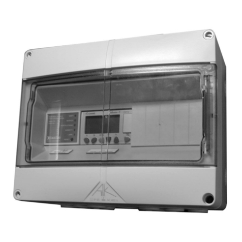
Swegon SuperWISE II a User manual

Swegon

Swegon SuperWISE II a User manual

Swegon CRTc Guide

Swegon

Swegon CRTc Guide

Swegon TBLZ-1-66 User manual

Swegon

Swegon TBLZ-1-66 User manual

Swegon TBLZ-1-48-2 GOLD User manual

Swegon

Swegon TBLZ-1-48-2 GOLD User manual

Swegon IQlogic+ TBIQ-3-2-aa GOLD User manual

Swegon

Swegon IQlogic+ TBIQ-3-2-aa GOLD User manual

Swegon WISE Parasol Z b Series User manual

Swegon

Swegon WISE Parasol Z b Series User manual

Swegon CONDUCTOR User manual

Swegon

Swegon CONDUCTOR User manual

Swegon Parasol ma User manual

Swegon

Swegon Parasol ma User manual

Swegon Parasol evo II ma User manual

Swegon

Swegon Parasol evo II ma User manual

Swegon TBLZ-1-48-1 User manual

Swegon

Swegon TBLZ-1-48-1 User manual

Swegon TBIQ-2-1-aa IQnomic Plus GOLD User manual

Swegon

Swegon TBIQ-2-1-aa IQnomic Plus GOLD User manual

Swegon CRM User manual

Swegon

Swegon CRM User manual

Swegon SuperWISE II User manual

Swegon

Swegon SuperWISE II User manual

Swegon CCO kit User manual

Swegon

Swegon CCO kit User manual

Swegon TBLZ-2-48-2 User manual

Swegon

Swegon TBLZ-2-48-2 User manual

Swegon TBIQ-3-1 Instruction and safety manual

Swegon

Swegon TBIQ-3-1 Instruction and safety manual

Swegon TBLZ-3-50 Parts list manual

Swegon

Swegon TBLZ-3-50 Parts list manual

Swegon P.LEMMENS CB4 TAC4 REC User manual

Swegon

Swegon P.LEMMENS CB4 TAC4 REC User manual

Popular Control Unit manuals by other brands

Allen-Bradley 1732ES-IB16 user manual

Allen-Bradley

Allen-Bradley 1732ES-IB16 user manual

Agilent Technologies 83400 Series user guide

Agilent Technologies

Agilent Technologies 83400 Series user guide

Flowserve Argus EK Series Installation, commissioning maintenance

Flowserve

Flowserve Argus EK Series Installation, commissioning maintenance

Tridonic basicDIM Wireless installation instructions

Tridonic

Tridonic basicDIM Wireless installation instructions

M-system Mini-M M2MNV instruction manual

M-system

M-system Mini-M M2MNV instruction manual

Casit EQ211/02 quick start guide

Casit

Casit EQ211/02 quick start guide

Bardiani Valvole BBZPM instruction manual

Bardiani Valvole

Bardiani Valvole BBZPM instruction manual

Blue Point Engineering DMX Analyzer manual

Blue Point Engineering

Blue Point Engineering DMX Analyzer manual

UTC Fire and Security interlogix VT1101M Installation & operation instructions

UTC Fire and Security

UTC Fire and Security interlogix VT1101M Installation & operation instructions

ADTRAN Octal E&M user manual

ADTRAN

ADTRAN Octal E&M user manual

Eclipse 200 LT Series instruction manual

Eclipse

Eclipse 200 LT Series instruction manual

Allen-Bradley Rockwell Automation 1734-4IOL user manual

Allen-Bradley

Allen-Bradley Rockwell Automation 1734-4IOL user manual

Feasycom FSC-BT95X Series user guide

Feasycom

Feasycom FSC-BT95X Series user guide

Xilica Audio Design XTouch Series: XTouch50 user manual

Xilica Audio Design

Xilica Audio Design XTouch Series: XTouch50 user manual

Cornelius MFV How-to

Cornelius

Cornelius MFV How-to

Kyocera KD205GX-LPU installation manual

Kyocera

Kyocera KD205GX-LPU installation manual

Aluprof AL-BR01 Installation, Assembly and Operating Manual

Aluprof

Aluprof AL-BR01 Installation, Assembly and Operating Manual

Comelit 41ECN000 Installation instruction

Comelit

Comelit 41ECN000 Installation instruction

manuals.online logo
manuals.online logoBrands
  • About & Mission
  • Contact us
  • Privacy Policy
  • Terms and Conditions

Copyright 2025 Manuals.Online. All Rights Reserved.