AAA-055-00020
JAY•LOR
Operator’s Manual
- 2 -
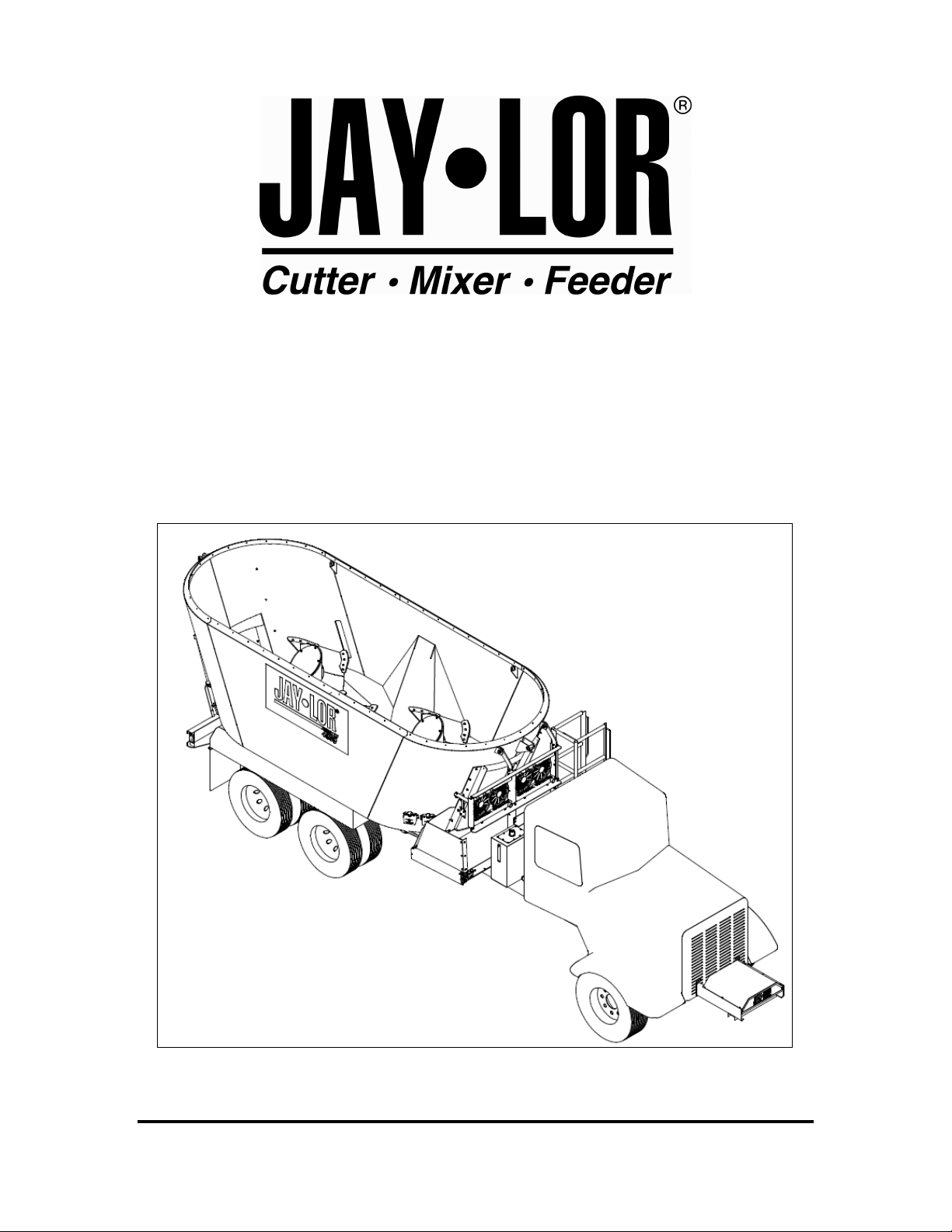
Trailer Units
LIMITED WARRANTY
JAY•LOR
FABRICATING INC. the Seller) warrants the articles and units sold to be free from
defects in material and workmanship and to conform to applicable specifications. These express
warranties are the sole warranties of the Seller, and any other warranties, express, implied in law
or implied in fact, are hereby specifically excluded. Refer to the Operator’s Manual content for
any applicable warranties expressed otherwise.
Seller’s sole obligation under its warranties will be, at its option, to repair or replace any article or
part thereof which is proved to be other than warranted. Obligation under this warranty will be
limited to replacement or repair of parts found, upon Seller’s inspection, to be defective. All
warranties shall expire 12 months from the date the unit or article is placed in service, or 12
months from the date the article or unit is delivered by the Seller, whichever expires first.
NO ALLOWANCES WILL BE MADE TO THE BUYER FOR ANY TRANSPORTATION, LABOUR
CHARGES, PARTS ADJUSTMENTS OR REPAIRS, OR ANY OTHER WORK, UNLESS THESE
CHARGES ARE AUTHORIZED IN ADVANCE BY THE SELLER.
The Seller shall in no event be liable for special or consequential damages. If an article is
claimed to be defective in material or workmanship, or does not conform to specifications, the
Seller, upon notice promptly given, will either examine the article or unit at its site, or issue
shipping instructions to return to the Seller. The warranties shall not extend to any articles, units,
or parts thereof which have been installed, used, or serviced, otherwise than in conformance with
the Seller’s applicable instructions, manuals, service bulletins, or, if none, which shall have been
articles, units, parts thereof furnished by the Buyer or acquired from others at the Buyer’s request
and/or Buyer’s specifications.
The warranties are not applicable for expenses either direct or consequential that may arise from
the use or inability to use the articles and units sold by the Seller. The Seller shall in no event be
responsible for and will not be held liable for losses, injury, or damage caused to persons or
property by reason of operation of Seller’s products or their failure.
This warranty does not cover parts and accessories that are under separate guarantees from the
manufacturers and service can be obtained from their service facilities in USA and Canada. No
warranty is extended to regular service items such as fluid, paint, tires, knives and the like.
This warranty pertains to components manufactured or installed by JAY•LOR
Fabricating Inc.
only. This hereby excludes any warranties offered separately such as those offered by the truck
manufacturer. In this event, please refer to the appropriate Warranty Statements offered by the
separate manufacturer.
All claims for warranty must be directed to your dealer or distributor.
WARRANTY VOID IF NOT REGISTERED