JBL SYNTHESIS SCL-5 User manual

SCL-5 / SCL-8
In-Ceiling Loudspeakers/Enceintes en plafond/
Deckeneinbau-Lautsprecher/Altavoces integrables en el
techo/Alto-falantes de teto/Акустические системы для
монтажа в потолок/ 吸顶式扬声器 /
/천장 설치형 라우드 스피커
SCL-6 / SCL-7
In-Wall Loudspeakers/Enceintes encastrées/
Wandeinbau-Lautsprecher/Altavoces integrables en la
pared/Alto-falantes de parede/Акустические системы
для монтажа в стену/ 入墙式扬声器 /
/벽설치 라우드 스피커
OWNER’S AND INSTALLER’S MANUAL

English
2
CONTENTS
THANK YOU FOR CHOOSING JBL®............................................................................................................................................................................ 3
PACKAGE CONTENTS................................................................................................................................................................................................. 3
SPEAKER PLACEMENT FOR IN-CEILING AND IN-WALL ......................................................................................................................................... 3
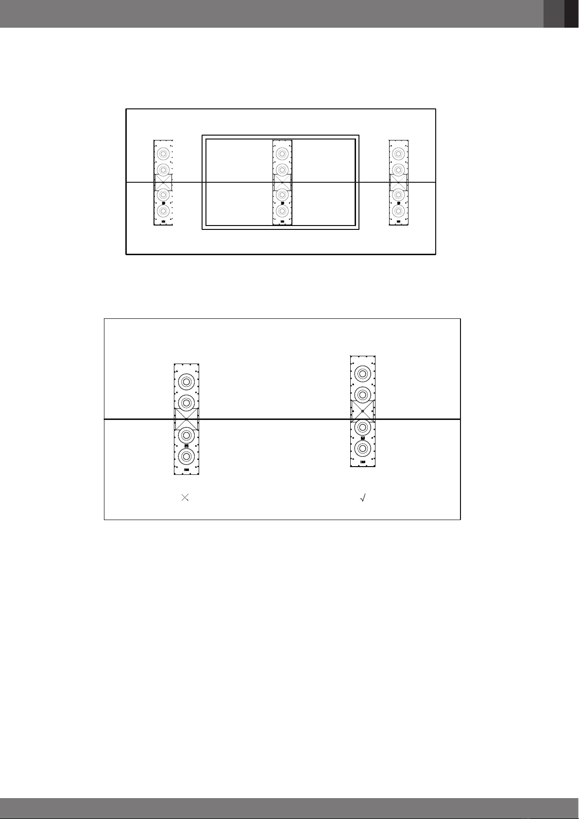
IN-WALL SPEAKER - LEFT AND RIGHT PLACEMENT .................................................................................................................................... 3
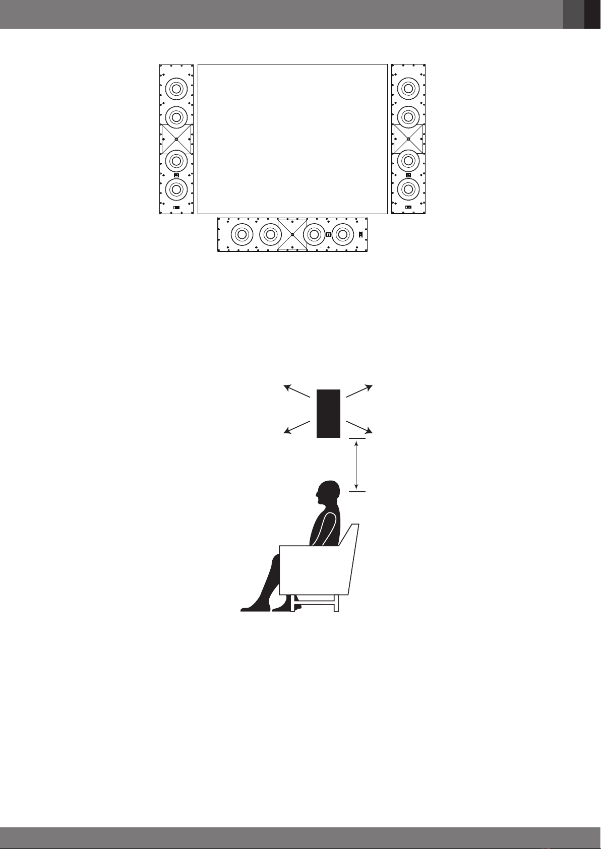
IN-WALL SPEAKER - CENTER CHANNEL PLACEMENT ................................................................................................................................ 4
IN-WALL SPEAKER - SURROUND PLACEMENT ............................................................................................................................................ 5
IN-WALL SPEAKEAR - 5.1-CHANNEL SYSTEMS PLACEMENT ..................................................................................................................... 5
IN-WALL SPEAKEAR - 7.1-CHANNEL SYSTEMS PLACEMENT ..................................................................................................................... 6
IN-CEILING SPEAKER - LEFT AND RIGHT PLACEMENT .............................................................................................................................. 6
IN-CEILING SPEAKEAR - 5.1-CHANNEL SYSTEMS PLACEMENT................................................................................................................. 7
IN-CEILING SPEAKEAR - 7.1-CHANNEL SYSTEMS PLACEMENT................................................................................................................. 7
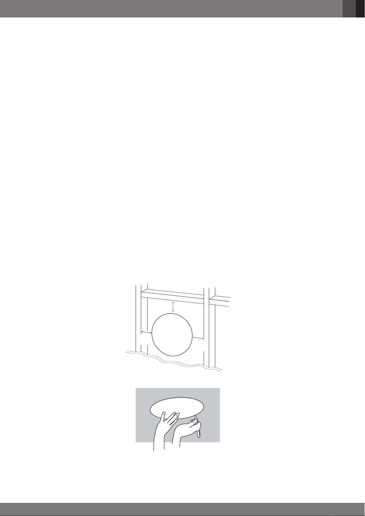
IN-CEILING INSTALLATION GUIDE .................................................................................................................................................................. 8
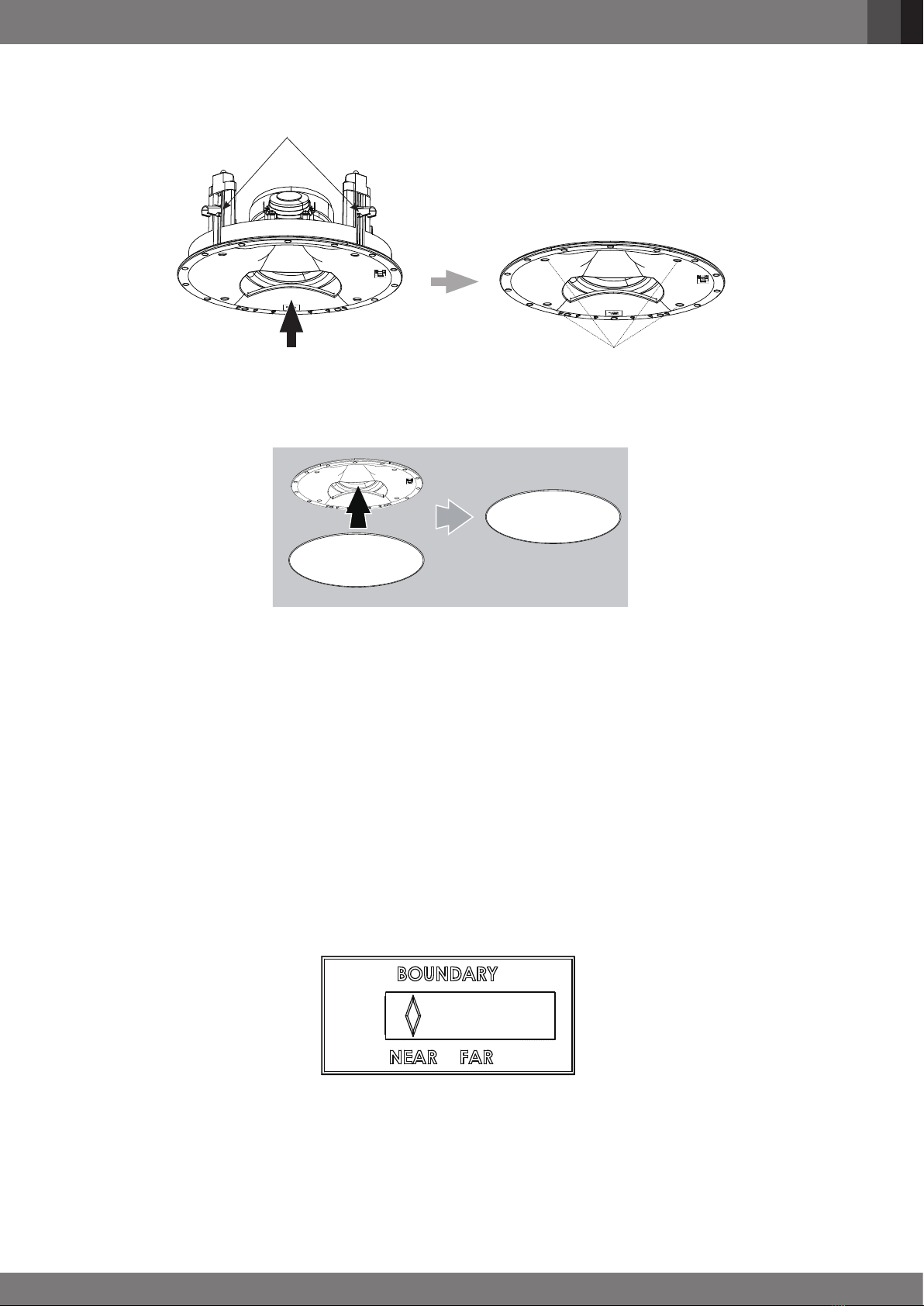
PAINTING THE GRILLE ................................................................................................................................................................................... 10
BOUNDARY COMPENSATION CONTROL ..................................................................................................................................................... 10
SPECIFICATIONS........................................................................................................................................................................................................ 11
IMPORTANT SAFETY INSTRUCTIONS
1. Read these instructions.
2. Keep these instructions.
3. Heed all warnings.
4. Follow all instructions.
5. Clean only with a dry cloth.
6. Do not block any ventilation openings. Install this apparatus in accordance
with the manufacturer’s instructions.
7. Do not install this apparatus near any heat sources such as radiators, heat
registers, stoves or other apparatus (including ampliers) that produce heat.
8. Use only attachments/accessories specied by the manufacturer.
9. Use only with the cart, stand, tripod, bracket or table specied
by the manufacturer or sold with the apparatus. When a
cart is used, use caution when moving the cart/apparatus
combination to avoid injury from tip-over.
10. Refer all servicing to qualied service personnel. Servicing is
required when the apparatus has been damaged in any way, such as when
the power-supply cord or plug is damaged, liquid has been spilled or objects
have fallen into the apparatus, or the apparatus has been exposed to rain or
moisture, does not operate normally or has been dropped.
Correct disposal of this product (Waste Electrical & Electronic Equipment)
This symbol means the product must not be discarded as household waste,
and should be delivered to an appropriate collection facility for recycling. Proper
disposal and recycling helps protect natural resources, human health and the
environment. For more information on disposal and recycling of this product,
contact your local municipality, disposal service, or the shop where you bought
this product.
RoHS
This product is RoHS compliant.
This product is in compliance with Directive 2011/65/EU, and its amendments,
on the restriction of the use of certain hazardous substances in electrical and
electronic equipment.
REACH
REACH (Regulation No 1907/2006) addresses the production and use of
chemical substances and their potential impacts on human health and the
environment. Article 33(1) of REACH Regulation requires suppliers to inform the
recipients if an article contains more than 0.1 % (per weight per article) of any
substance(s) on the Substances of Very High Concern (SVHC) Candidate List
('REACH candidate list'). This product contains the substance "lead"(CAS-No.
7439-92-1) in a concentration of more than 0.1% per weight.
At the time of release of this product, except for the lead substance, no other
substances of REACH candidate list are contained in a concentration of more
than 0.1% per weight in this product.
Note: On June 27, 2018, lead was added to the REACH candidate list. The
inclusion of lead in the REACH candidate list does not mean that lead-containing
materials pose an immediate risk or results in a restriction of permissibility of its
use.

English
English
3
THANK YOU FOR CHOOSING JBL®
For more than 70 years, JBL engineers have been providing audio equipment for homes, concert halls, recording studios and movie theaters around
the world, and JBL products have become the hands-down choice of leading recording artists and sound engineers. The SCL-5, SCL-6, SCL-7, and
SCL-8 are the latest members of the JBL Synthesis Home Theater line. To get the best performance from your new loudspeakers, please read these
instructions thoroughly.
PACKAGE CONTENTS
EACH JBL SCL-5 / SCL-6 / SCL-7 / SCL-8 PACKAGE CONTAINS:
1x SCL-6 or 1x SCL-7 1x Quick Start Guide1x Square Grille 1x Template 1x Scrim Cloth
Quick
Start
Guide
Grille
Template
1x SCL-5 or 1x SCL-8 1x Round and 1x Square Grilles 1x Template 1x Quick Start Guide
Grille Template
Grille Quick
Start
Guide
2x Scrim Cloths
If you suspect that there has been shipping damage, report it immediately to your dealer. We recommend that you keep the box and packing
materials for future use.
SPEAKER PLACEMENT FOR IN-CEILING AND IN-WALL
Positioning your loudspeakers properly is critical in order to achieve the sonic performance of a home theater. Please read the following section for
guidance in correct and optimal placement.
Notes: For In-wall installation, please refer to bracket accesonies WB52 or WB54 which are sold separately.
IN-WALL SPEAKER - LEFT AND RIGHT PLACEMENT
The SCL-6 and SCL-7 are perfect choice to serve as front left and right main speakers in a multi-channel system. Since they have been designed for
uniform coverage and maximum dispersion of sound, they should be placed with the center of the speakers at about the same height on screen as
the actors to aid in the illusion that the actors’ voices are coming directly from their on-screen images. Ideally, the speakers will be placed about 60
degrees apart from each other viewed from the listening position, so that the distance between the speakers is the same as each speaker’s distance
from the listener (Figure 1).
L
C
R
LEFT
SIDE
RIGHT
SIDE
LEFT
SIDE
RIGHT
SIDE
Video Display
SCL-7 SCL-6
Figure 1 Figure 2

English
4
IN-WALL SPEAKER - CENTER CHANNEL PLACEMENT
The SCL-6 or SCL-7 may be oriented either vertically or horizontally when used as a center channel speaker. If the speaker is being used with a
perforated projection screen, it should be mounted behind the center of the screen with the horizontal center axis aligned as close as possible to the
center axis of the Left and Right channel speakers (Figure 3).
L
C
R
LEFT
SIDE
RIGHT
SIDE
Center Axis
Figure 3
NOTE: Some perforated projection screens have a batten bar or crossbar centered across the screen frame (Figure 4). In such cases make sure
the bar does not block the horn. Position vertically oriented speakers so that the bar crosses in front of the speakers at the edge of the horn closest
to the central woofer.
LCD TV
×
√
Batten bar or crossbar
Figure 4
If a non-perforated projection screen, LCD/plasma/OLED display is being used in the installation, the SCL-6 or SCL-7 may be used in horizontal
orientation mounted directly below or above and as close as possible to the video display (Figure 5).
NOTE: It is extremely important to place the center, left and right speakers as close as possible to the same height. The horn in the center channel
speaker should be no more than 2 feet (61cm) higher or lower than those in the left and right speakers. This preserves the localization integrity of
"sound pans" in which the sound appears to move from left to center to right.

English
English
5
LCD TV
×
√
Figure 5
IN-WALL SPEAKER - SURROUND PLACEMENT
Please consult your authorized JBL Synthesis dealer for selection of appropriate JBL Synthesis speakers for your home theater.
IN-WALL SPEAKEAR - 5.1-CHANNEL SYSTEMS PLACEMENT
Surround speakers should be placed in the side walls no closer to the screen than the rst row of viewing chairs. If there are two rows of chairs,
these speakers should be placed between the two rows. Surround speakers should be placed higher than the seating area, at least 2 feet above
seated ear level (Figure 6).
Min. 2'-0"
L
C
R
Min. 2'-0"
Figure 6

English
6
IN-WALL SPEAKEAR - 7.1-CHANNEL SYSTEMS PLACEMENT
In a 7.1-channel system, two speakers are added for rear ll, in addition to the surround speakers in a 5.1-channel system. The two additional
speakers are placed on the rear wall or near the rear wall in the ceiling (Figure 7).
Video Display
Min. 2'-0"
L
C
R
LEFT
SIDE
LEFT
REAR
RIGHT
REAR
RIGHT
SIDE
Figure 7
IN-CEILING SPEAKER - LEFT AND RIGHT PLACEMENT
Place the left and right loudspeakers the same distance from the primary listening area (or as close to the same distance as possible). The distance
from each speaker to its nearest side wall should also be as close to the same distance as possible.
Video Display
Equal
Distance
Equal
Distance
Left Right
Ideally, the distance between the left and right loudspeakers should be slightly less than their distance from the primary listening area.

English
English
7
IN-CEILING SPEAKEAR - 5.1-CHANNEL SYSTEMS PLACEMENT
• The surround left and surround right loudspeakers should be located to the sides of, and approximately 10 degrees behind, the main listening
area.
• The front left, center and front right loudspeakers should be centered relative to the video display.
• The front left, center, and front right loudspeakers should be closer to the video display than to the main listening area. For example, if the
video display is 10 ft (3m) from the main listening area, the loudspeakers should be 6 ft (1.8m) or further from the main listening area.
• The front left and front right loudspeakers should be relatively close to the sides of the video display. For example, front left and front right
loudspeakers used with a 50-in (1.2m) video display should generally not be more than 80 in (2m) apart.
• The center loudspeaker should be aligned with the center of the video display.
• The surround-channel loudspeakers should be as far from the main listening area as possible but at least 2 feet (0.6m) from side and front
walls.
cfb0c216-2f7d26f9-80d19b09-9abcf37f
b4de33ee-7c3b831d-47faa6b3-0debe002b4de33ee-7c3b831d-47faa6b3-0debe002
b4de33ee-7c3b831d-47faa6b3-0debe002
b61f61fc-510d3cc3-56ad1695-de6293e2
Video Display
Center
0°- 10°
Surround Left Surround Right
Front Left Front Right
More than
2' (0.6m)
IN-CEILING SPEAKEAR - 7.1-CHANNEL SYSTEMS PLACEMENT
• Two speakers are added for rear ll, in addition to the surround speakers in a 5.1-channel system. The two additional speakers are placed on
the rear wall or near the rear wall in the ceiling.
• The surround back left and surround back right loudspeakers should be equidistant from the primary listening area and generally as far from it
as possible but at least 2 ft (0.6m) from the side and rear walls.
cfb0c216-2f7d26f9-80d19b09-9abcf37f
b4de33ee-7c3b831d-47faa6b3-0debe002b4de33ee-7c3b831d-47faa6b3-0debe002
b4de33ee-7c3b831d-47faa6b3-0debe002
b61f61fc-510d3cc3-56ad1695-de6293e2
Video Display
Center
0°- 10°
Surround Left Surround Right
Front Left Front Right
More than
2' (0.6m)
More than
2' (0.6m)
More than
2' (0.6m)
Surround
Back Left
Surround
Back Right

English
8
WARNING: HARMAN International assumes no responsibility for improper installation of hardware or for any personal injuries or product
damages resulting from improper installation or a fallen loudspeaker.
PREPARING THE HOOK-UP WIRE
1. First determine the distance between your amplier and the most distant speaker in each group (fronts, surrounds, back surrounds, passive
subwoofers).
2. Now make the hookup wires for all speakers in each group this length, even if one speaker is much closer to your amplier than the other.
This will help maintain proper signal balance. Remember to make extra wires for bi-amp or bi-wire usage should this be selected.
3. Strip off 3/8" of insulation from both ends of each conductor.
4. Twist each set of stranded wires into a tightly bunched spiral. Run wires through walls to the mounting positions.
5. Speakers and electronics terminals have corresponding (+) and (–) terminals. Most manufacturers of speakers and electronics, including JBL,
Inc., use red to denote the (+) terminal and black for the (–) terminal. Please conrm before connecting.
It is important to connect all speakers identically: (+) on the speaker to (+) on the amplier and (–) on the speaker to (–on the amplier. Wiring "out of
phase" (+ to - and - to +) results in thin sound, weak bass and poor imaging.
With multichannel surround sound systems, connecting all of the speakers in your system with the correct polarity remains equally important to
preserve the proper ambience and frequency response of the program material.
Now nd a visual difference between the two conductors of each molded pair of speaker wires. Differentiating marks can be a different color wire
(copper or silver); a strand of yarn in one conductor; thin, raised ribs on one part of the outer insulation; or a printed marking on one part of the outer
insulation. It doesn’t matter which of the two strands go to the (+) and (–) on the speakers and ampliers, as long as all speakers are connected
identically. When attaching to the back box, push on the top of the spring-loaded post and insert the bare wire into the hole on the side.
IN-CEILING INSTALLATION GUIDE
For New Construction
If you wish to pre-install a rough-in frame for the speakers before the drywall is installed in new construction, you will need to purchase the correct
rough-in frame kit for your loudspeaker model from your authorized JBL Synthesis dealer. Detailed mounting instructions are supplied with the
rough-in kit. After the drywall is installed, follow the installation instructions in For Existing Construction, below.
For Existing Construction
Note: The installation procedure is the same for all models covered by this manual.
1. Ensure that the drywall, plywood or other ceiling material is 1/2" - 2" (13mm - 51mm) thick and capable of withstanding the weight of the
speaker being installed.
Make sure to allow at least 3/4" (19mm) between the edge of the supplied installation template and any rafters or other obstructions behind the
wall, so the speaker's locking mechanism will have room to engage fully Perform an obstruction survey to be sure that there are no studs, lengths of
conduit, pipes, heating ducts or air returns in the ceiling cavity that will interfere with the speaker.
Mounting
Opening
3/4"
(19mm)
3/4"
(19mm)
3/4"
(19mm)
2. Determine the correct speaker location and use the template included with the speaker to mark the ceiling material.
Template

English
English
9
3. Cut the ceiling drywall along the mark you made in Step 2 to create the mounting opening.
4. Connect the speaker to the amplier as explained on page 8.
5. Attach the speaker's seismic tab to a support line, as per local safety regulations.
Support Line
Seismic Tab
6. Make sure all speaker clamps are in their "ready-to-mount" position.
Speaker Clamps in
Ready-to-Mount Positon
7. Insert the speaker straight into the mounting opening. Tighten the speaker clamp screws on the front of the speaker bafe. The speaker
clamps will automatically rotate into position and begin clamping the speaker. When you notice resistance on the screws the speaker has
been clamped successfully.

English
10
IMPORTANT: Always use low-torque settings. NEVER over-tighten the clamp screws.
Speaker Clamps Inside
Mounting Cut-Out
Insert Speaker Straight Into
Mounting Cut-Out
Tighten Clamping Screws
8. Attach the supplied round or square grille. Powerful magnets in the speaker frame will securely hold the grille in place.
Attach Supplied Grille
PAINTING THE GRILLE
JBL Synthesis architectural loudspeaker grilles can be painted to match any decor. If you wish to change the grille's color, its satin nish will function
as a primer coat. For the best results follow this procedure:
1. Gently remove the scrim cloth from the back side of the grille before painting.
2. Use a high-quality spray paint and apply a thin coat of color. Ensure that the grille perforations remain free of paint. Filling them with paint will
diminish the speaker's sound quality. If any perforations are plugged, use compressed air to blow the paint out of the perforations.
Note: If you nd any grille perforations that are plugged with paint after the paint has dried, carefully use a straight pin or sewing
needle to remove the paint.
3. We have included round and/or rectangular replacement scrim cloths. After the paint has dried, apply a light coat of spray adhesive to the
inside of the perforated grille and attach a new scrim cloth. IMPORTANT: Never spray adhesive on the cloth. The scrim cloth on model SCL-5
or SCL-8 has pre-attached foam pads that help prevent the square grille from vibrating against the ceiling.
BOUNDARY COMPENSATION CONTROL
The Boundary Compensation control reduces the speaker's bass output level to compensate for the greater reection of bass energy when the
speaker is placed near a wall.
When possible, avoid mounting the speaker within 2 ft (0.6m) of a wall. If such placement is unavoidable, set the Boundary Compensation control to
the "NEAR" position.

English
English
11
SPECIFICATIONS
SCL-5 SCL-8
Type: 2-Way In-ceiling loudspeaker
Low Frequency Driver: 7" (180mm) advanced Aluminum Matrix cone cast-
frame woofer (JW180PB-6)
5.25" (130mm) advanced Aluminum Matrix cone cast-
frame woofer (JW130Al-4)
High Frequency Driver: 1" (25mm) 2409H Teonex®annular ring-diaphragm
compression driver
1" (25mm) 2410H-2 Teonex®annular ring-diaphragm
compression driver
Recommended Amplier Power: 25 – 125W RMS 25 - 100W RMS
Impedance: 6Ohms 4Ohms
Loudspeaker Sensitivity: 86dB/2.83 V/1m 85dB/2.83 V/1m
Frequency Response: 48Hz - 32kHz (-6dB on-axis), 2pi anechoic 55Hz - 30kHz (-6dB on-axis), 2pi anechoic
Crossover Frequency: 1575Hz 1.8kHz
High Frequency Coverage Angle (-6 dB): 60° Vertical (Up: 30°, Down: 30°, from 45° Vertical
Center line), 120° Horizontal, from 2kHz to 10kHz.
60° Vertical (Up: 30°, Down: 30°, from 45° Vertical
Center line), 120° Horizontal, from 2kHz to 10kHz.
Enclosure Type: Open back
Controls: Boundary Proximity Control
Grille Dimensions: Round: 12.52" (318mm) x 0.28" (7mm)
Square: 12.52" (318mm) x 12.52" (318mm) x
0.28" (7mm)
Round: 10.75" (273mm) x 0.25" (6.2mm)
Square: 10.75" (273mm) x 10.75" (273mm) x
0.25" (6.2mm)
Product Dimensions (with grille): 12.5" H x 12.5" W x 5.98" D
(318mm x 318mm x 151.9mm)
10.77" H x 10.77" W x 4.73" D
(273mm x 273mm x 120mm)
Cut-out Diameter: 11.22" (285mm) 9.72" (247mm)
Mounting Depth: 5.58" (141.8mm) 4.68" (119mm)
Input Type Dual gold-plated spring-loaded binding posts
Product Weight: 8.6lb. (3.9kg) 7.8lb. (3.5kg)
Shipping Weight: 12.5lb. (5.7kg) 10.6lb. (4.8kg)
Shipping Units of Measure: Each
Warranty: 5 Years
SCL-6 SCL-7
Type: 2.5-way In-Ceiling loudspeaker
Low Frequency Driver: Quad 5.25" (130mm) Black Anodized Aluminum cone
woofer (JW130Al-4)
Dual 5.25" (130mm) Black Anodized Aluminum cone
woofer (JW130Al-8)
High Frequency Driver: 1" (25mm) 2401H-2 annular ring, Teonex®diaphragm
compresion driver
1" (25mm) 2401H-2 annular ring, Teonex®diaphragm
compresion driver
Recommended Amplier Power: 25 - 200W RMS 25 - 150W RMS
Impedance: 4Ohms 4Ohms
Loudspeaker Sensitivity: 91dB/2.83 V/1m 88dB/2.83 V/1m
Frequency Response: 50Hz-30kHz (-6dB on-axis), 2pi anechoic 55Hz-30kHz (-6dB on-axis), 2pi anechoic
Crossover Frequency: 1.8kHz 2.0kHz
High Frequency Coverage Angle (-6 dB): 80° Ver X 80° Hor from 2kHz to 17kHz 60° Ver, 90° Hor (Left: 30°, Right: 60°, from center line),
from 2kHz to 15kHz
Enclosure Type: Open back
Controls: Boundary Proximity Control
Grille Dimensions: 7.28" (185mm) X 31.34" (796mm) X 0.25" (6.2mm) 7.32" (186mm) X 19.14" (486mm) X 0.25" (6.2mm)
Product Dimensions (with grille): 7.29" (185mm) X 31.32" (796mm) X 3.82" (97.1mm) 7.32" (186mm) X 19.15" (486mm) X 3.88" (99mm)
Cut-out Diameter: 30.18" (766mm) x 6.18" (157mm) 18.03" (458mm) x 6.18" (157mm)
Mounting Depth: 3.82" (97mm) 3.82" (97mm)
Input Type Dual gold-plated spring-loaded binding posts
Product Weight: 22.2lbs (10.07kg) 12.6lbs (5.72kg)
Shipping Weight: 25.6lbs (11.61kg) 14.6lbs ( 6.62kg)
Shipping Units of Measure: Each
Warranty: 5 Years
Note: Dimensions are subject to change without notice.

12
Français
CONSIGNES DE SÉCURITÉ IMPORTANTES
1. Lisez ces instructions.
2. Conservez ces instructions.
3. Tenez compte de tous les avertissements.
4. Suivez toutes les instructions.
5. Nettoyez uniquement avec un chiffon sec.
6. Ne bouchez aucune ouverture de ventilation. Installez cet appareil
conformément aux instructions du fabricant.
7. N’installez pas cet appareil à proximité d’une source de chaleur telle que des
radiateurs, des bouches de chaleur, des fourneaux ou d’autres appareils (y
compris les amplicateurs) qui produisent de la chaleur.
8. Utilisez seulement des compléments/accessoires spéciés par le
constructeur.
9. Utilisez l'appareil seulement avec le chariot, pied, trépied,
support ou table spécié par le constructeur, ou vendu avec
l'appareil. Lors de l'utilisation d'un chariot, faites attention
en déplaçant l'ensemble chariot/appareil an d'éviter des
blessures dues à un basculement.
10. Toutes les réparations doivent être effectuées par un personnel qualié.
Une révision est nécessaire si l’appareil a été endommagé d'une façon
quelconque, si le cordon ou la che d'alimentation sont endommagés, si du
liquide a été renversé sur l'appareil ou si des objets sont tombés dedans,
si l’appareil a été exposé à la pluie ou à l’humidité, s'il ne fonctionne pas
normalement ou s'il est tombé.
Élimination correcte de ce produit (Déchets d’équipements électriques et
électroniques)
Ce symbole signie que le produit ne doit pas être jeté comme déchet ménager
et doit être remis à une installation de collecte appropriée pour son recyclage.
Une élimination et un recyclage appropriés aident à protéger les ressources
naturelles, la santé humaine et l’environnement. Pour obtenir plus d’informations
sur l’élimination et le recyclage de ce produit, contactez votre municipalité locale,
le service de gestion des déchets ou le magasin où vous avez acheté ce produit.
RoHS
Ce produit est conforme à la RoHS.
Ce produit est conforme à la directive 2011/65/UE et à ses amendements sur
la restriction de l'utilisation de certaines substances dangereuses dans les
équipements électriques et électroniques.
REACH
REACH (règlement N° 1907/2006) concerne la production et l'utilisation de
substances chimiques ainsi que leurs impacts potentiels sur la santé humaine
et l'environnement. L’article 33(1), du règlement REACH exige des fournisseurs
qu’ils informent les destinataires si un article contient plus de 0,1% (par poids
et par article) d’une ou plusieurs substances gurant sur la liste candidate
des substances extrêmement préoccupantes (SVHC, substances of very
high concern) (« Liste candidate REACH »). Ce produit contient la substance
« plomb » (N° CAS 7439-92-1) à une concentration supérieure à 0,1 % en
masse.
Au moment de la production de ce produit, à part la substance plomb, aucune
autre substance de la liste des candidates REACH n’est présente à une
concentration supérieure à 0,1 % en masse dans ce produit.
Remarque : Le 27 juin 2018, le plomb a été ajouté à la liste des substances
candidates REACH. L'inclusion du plomb dans la liste des substances candidates
REACH ne signie pas que les matériaux contenant du plomb posent un risque
immédiat et ne conduit pas à une restriction d’autorisation de leur utilisation.
TABLE DES MATIèRES
MERCI D'AVOIR CHOISI JBL®.................................................................................................................................................................................... 13
CONTENU DE L’EMBALLAGE................................................................................................................................................................................... 13
POSITIONNEMENT DES ENCEINTES DANS UN PLAFOND ET DANS UN MUR ................................................................................................... 13
ENCEINTE ENCASTRÉE - POSITIONNEMENTS GAUCHE ET DROIT......................................................................................................... 13
ENCEINTE ENCASTRÉE - POSITIONNEMENT DU CANAL CENTRAL ....................................................................................................... 14
ENCEINTE ENCASTRÉE - POSITIONNEMENT DU SURROUND ................................................................................................................ 15
ENCEINTE ENCASTRÉE - POSITIONNEMENT DU SYSTÈME POUR 5.1 CANAUX .................................................................................. 15
ENCEINTE ENCASTRÉE - POSITIONNEMENT DU SYSTÈME POUR 7.1 CANAUX .................................................................................. 16
ENCEINTE EN PLAFOND - POSITIONNEMENTS GAUCHE ET DROIT ....................................................................................................... 16
ENCEINTE EN PLAFOND - POSITIONNEMENT DU SYSTÈME POUR 5.1 CANAUX .................................................................................. 17
ENCEINTE EN PLAFOND - POSITIONNEMENT DU SYSTÈME POUR 7.1 CANAUX .................................................................................. 17
GUIDE D’INSTALLATION EN PLAFOND......................................................................................................................................................... 18
PEINTURE DE LA GRILLE............................................................................................................................................................................... 20
COMMANDE DE COMPENSATION DE BORD ............................................................................................................................................... 20
CARACTÉRISTIQUES TECHNIQUES........................................................................................................................................................................ 21

13
Français
Français
MERCI D'AVOIR CHOISI JBL®
Depuis plus de 70 ans, les ingénieurs de JBL fournissent des équipements audio aux particuliers, aux salles de concert, aux studios d'enregistrement
et aux cinémas du monde entier, les produits JBL sont devenus le choix unanime des artistes de studio et des ingénieurs du son les plus renommés.
Les SCL-5, SCL-6, SCL-7 et SCL-8 sont les tout derniers membres du ligne de cinéma à domicile JBL Synthesis. Veuillez lire ces instructions
attentivement pour obtenir les meilleures performances de vos nouvelles enceintes.
CONTENU DE L’EMBALLAGE
CHAQUE EMBALLAGE DE JBL SCL-5 / SCL-6 / SCL-7 / SCL-8 CONTIENT :
1 SCL-6 ou 1 SCL-7 1 guide de démarrage rapide1 grille carrée 1 gabarit 1 voile
Guide de
démarrage
rapide
Grille
Modèle
1 SCL-5 ou 1 SCL-8 1 grille ronde et 1 grille carrée 1 gabarit 1 guide de
démarrage rapide
Grille Modèle
Grille
Guide de
démarrage
rapide
2 voiles
Si vous pensez que le transport a provoqué des dommages, rapportez-la immédiatement à votre distributeur. Nous vous recommandons de
conserver la boîte et les matériaux d'emballage pour une utilisation ultérieure.
POSITIONNEMENT DES ENCEINTES DANS UN PLAFOND ET DANS UN MUR
Le bon positionnement de vos enceintes est essentiel pour obtenir les performances sonores d'un cinéma à domicile. Veuillez lire les conseils pour
un positionnement correct et optimal dans la section suivante.
Remarques : Pour une installation encastrée, veuillez vous référer aux supports accessoires WB52 ou WB54 vendus séparément.
ENCEINTE ENCASTRÉE - POSITIONNEMENTS GAUCHE ET DROIT
Les SCL-6 et SCL-7 sont le choix parfait comme enceintes principales avant gauches ou droites dans un système multicanal. Son design étant
prévu pour une couverture uniforme et une dispersion sonore maximale, son centre doit être placé à environ la même hauteur d'écran que les
acteurs an de renforcer l'illusion que leurs voix proviennent directement de leurs images à l'écran. Idéalement, les enceintes seront écartées
d'environ 60 degrés, vues de la position d'écoute, an que la distance qui les sépare soit égale à la distance entre les enceintes et l'auditeur
(gure 1).
L
C
R
LEFT
SIDE
RIGHT
SIDE
CÔTÉ
GAUCHE
CÔTÉ
DROIT
Afchage vidéo
SCL-7 SCL-6
Figure 1 Figure 2

14
Français
ENCEINTE ENCASTRÉE - POSITIONNEMENT DU CANAL CENTRAL
Les SCL-6 et SCL-7 peuvent être orientées verticalement ou horizontalement lorsqu’elles sont utilisées en tant qu’enceinte centrale. Si l'enceinte est
utilisée avec un écran de projection perforé, elle doit être montée derrière le centre de l'écran avec son axe central horizontal aligné aussi proche
que possible de l'axe central des enceintes des canaux gauches et droits (gure 3).
L
C
R
LEFT
SIDE
RIGHT
SIDE
Axe central
Figure 3
REMARQUE : Certains écrans de projection perforés comportent une latte ou une traverse centrée sur la trame de l'écran (gure 4). Vériez dans
de tels cas que la barre ne masque pas le pavillon. Positionnez des enceintes orientées verticalement de telle façon que la barre passe devant les
enceintes au bord du pavillon le plus proche au haut-parleur grave central.
LCD TV
×
√
Latte ou traverse
Figure 4
Si un écran de projection non perforé ou un écran LCD / plasma / OLED est utilisé dans l'installation, une SCL-6 ou SCL-7 peut être utilisée orientée
horizontalement et montée directement sous ou sur et aussi près que possible de l’écran vidéo (gure 5).
REMARQUE : Il est extrêmement important de placer les enceintes centrales, gauches et droites à la même hauteur. Le pavillon de l'enceinte du
canal central ne doit pas être plus haut ou plus bas de plus de 60 cm (2 pieds) de ceux des enceintes gauches et droites. Cela préserve l'intégrité
de la localisation des « panoramiques audio » qui donnent l'impression que le son se déplace de la gauche au centre et vers la droite.

15
Français
Français
LCD TV
×
√
Figure 5
ENCEINTE ENCASTRÉE - POSITIONNEMENT DU SURROUND
Veuillez consulter votre revendeur JBL Synthesis agréé pour sélectionner des enceintes JBL Synthesis adaptées à votre cinéma à domicile.
ENCEINTE ENCASTRÉE - POSITIONNEMENT DU SYSTèME POUR 5.1 CANAUX
Les enceintes d'ambiance doivent être placées dans les parois latérales, au moins à la distance de l’écran du premier rang de sièges de visionnage.
S'il y a deux rangs de sièges, ces enceintes doivent être placées entre des deux rangs. Les enceintes d'ambiance doivent être plus hautes que la
zone des sièges, au moins à 60 cm (2 pieds) au-dessus du niveau des oreilles des personnes assises (gure 6).
Min. 2'-0"
L
C
R
Min. 60 cm
(2’0")
Figure 6

16
Français
ENCEINTE ENCASTRÉE - POSITIONNEMENT DU SYSTèME POUR 7.1 CANAUX
Dans un système 7.1 canaux, deux enceintes sont ajoutées pour le remplissage arrière, en plus des enceintes d'ambiance d'un système 5.1 canaux.
Les deux enceintes supplémentaires sont placées sur la paroi arrière ou proche d'elle dans le plafond (gure 7).
Afchage vidéo
Min. 2'-0"
L
C
R
CÔTÉ
GAUCHE
ARRIERE
GAUCHE
ARRIERE
DROIT
CÔTÉ
DROIT
Figure 7
ENCEINTE EN PLAFOND - POSITIONNEMENTS GAUCHE ET DROIT
Placez les enceintes gauches et droites à la même distance de la zone d'écoute principale (ou aussi proches de la même distance que possible).
Les distances entre les enceintes et leurs parois latérales les plus proches doivent être aussi égales que possible.
Afchage
vidéo
Distance
égale
Distance
égale
Gauche Droite
Idéalement, la distance entre les enceintes gauches et droites doit être légèrement inférieure à leurs éloignements de la zone d'écoute principale.

17
Français
Français
ENCEINTE EN PLAFOND - POSITIONNEMENT DU SYSTèME POUR 5.1 CANAUX
• Les enceintes d'ambiance gauches et droites doivent se trouver sur les côtés et à environ 10 degrés en arrière de la zone d'écoute principale.
• Les enceintes avant gauches, centrales et avant droite doivent être centrées par rapport au moniteur vidéo.
• Les enceintes avant gauche, centrales et avant droites doivent être plus proches du moniteur vidéo que de la zone d'écoute principale. Par
exemple, si le moniteur vidéo est à 3 m (10 pieds) de la zone d'écoute principale, les enceintes doivent être au moins à 1,8 m (6 pieds) de
celle-ci.
• Les enceintes avant gauches et avant droites doivent être relativement proches des côtés du moniteur vidéo. Par exemple, des enceintes
avant gauches et avant droites utilisées avec un moniteur vidéo de 1,2 m (50 pouces) ne doivent généralement pas être séparées de plus de
2 m (80 pouces).
• L'enceinte centrale doit être alignée sur l'axe central du moniteur vidéo.
• Les enceintes de canal d'ambiance doivent être aussi loin de la zone d'écoute principale que possible, mais au moins à 0,6 m (2 pieds) des
parois latérales et frontale.
cfb0c216-2f7d26f9-80d19b09-9abcf37f
b4de33ee-7c3b831d-47faa6b3-0debe002b4de33ee-7c3b831d-47faa6b3-0debe002
b4de33ee-7c3b831d-47faa6b3-0debe002
b61f61fc-510d3cc3-56ad1695-de6293e2
Moniteur vidéo
Centre
0°- 10°
Surround gauche Surround droite
Avant gauche Avant droite
Plus de
0,6 m (2')
ENCEINTE EN PLAFOND - POSITIONNEMENT DU SYSTèME POUR 7.1 CANAUX
• Dans un système 5.1 canaux, deux enceintes sont ajoutées pour le remplissage arrière, en plus des enceintes d'ambiance. Les deux
enceintes supplémentaires sont placées sur la paroi arrière ou proche d'elle dans le plafond.
• Les enceintes d'ambiance surround arrière gauches et droites doivent être à égale distance de la zone d'écoute principale et en général aussi
éloignées de celle-ci que possible, mais au moins à 0,6 m (2 m) des parois latérales et arrière.
cfb0c216-2f7d26f9-80d19b09-9abcf37f
b4de33ee-7c3b831d-47faa6b3-0debe002b4de33ee-7c3b831d-47faa6b3-0debe002
b4de33ee-7c3b831d-47faa6b3-0debe002
b61f61fc-510d3cc3-56ad1695-de6293e2
Moniteur vidéo
Centre
0°- 10°
Surround gauche Surround droite
Avant
gauche Avant droite
Plus de
0,6 m (2')
Plus de
0,6 m (2')
Plus de
0,6 m (2')
Surround
arrière gauche
Surround
arrière droite

18
Français
AVERTISSEMENT : HARMAN International ne supporte aucune responsabilité pour une installation incorrecte du matériel, pour des
blessures ou des dommages aux produits provenant d'une installation incorrecte ou de la chute d'une enceinte.
PRÉPARATION DU CÂBLAGE
1. Déterminez d'abord la distance entre votre amplicateur et l'enceinte la plus éloignée de chaque groupe (avant, les ambiances, ambiances
arrière, caissons de graves passifs).
2. Préparez ensuite les câbles de toutes les enceintes de chaque groupe à cette longueur, même si une enceinte est beaucoup plus proche à
votre amplicateur que l'autre. Cela aidera à maintenir le bon équilibre du signal. N'oubliez pas de préparer des câbles supplémentaires en
cas de bi-amplication ou bicâblage si l'option doit être sélectionnée.
3. Dénudez 9,5 mm (3/8") d'isolant aux deux extrémités de chaque conducteur.
4. Torsadez chaque ensemble de ls toronnés en une spirale bien serrée. Faites passer les ls dans les murs jusqu'au aux positions de
montage.
5. Les enceintes et les bornes électroniques ont des bornes (+) et (-) correspondantes. La plupart des fabricants d'enceintes et d'électronique,
y compris JBL, Inc., utilisent le rouge pour la borne (+) et le noir pour la bornee (-). Veuillez conrmer avant le branchement.
Il est important de brancher toutes les enceintes de la même façon : (+) sur l'enceinte vers (+) sur l'amplicateur et (-) sur l'enceinte vers (-) sur
l'amplicateur. Le câblage « déphasé » (+ à - et - à +) produit un son étroit, des graves faibles et une image sonore dégradée.
Avec les systèmes audio d'ambiance surround multicanaux, le branchement de toutes les enceintes de votre système avec la polarité correcte est
également important pour conserver l'ambiance adéquate et la réponse en fréquence du contenu du programme.
Trouvez à présent une différence visuelle entre les deux conducteurs de chaque paire de ls d'enceintes moulés. Les signes de différenciation
peuvent être un l d'une couleur différente (cuivre ou argent), un l de coton dans un conducteur, des nervures sur une partie de l'isolant extérieur
ou un marquage imprimé sur une partie de l'isolant extérieur. Le choix de l'un des deux ls comme (+) et (-) sur les enceintes et les amplicateurs
n'a pas d'importance, tant que toutes les enceintes sont connectées de façon identique. Lors de la xation du boîtier arrière, poussez le haut de la
borne à ressort de rappel et insérez le l dénudé dans le trou latéral.
GUIDE D’INSTALLATION EN PLAFOND
Pour une construction neuve
Si vous souhaitez préinstaller une structure de base pour les enceintes avant la pose des cloisons sèches dans une construction neuve, vous
devrez acheter un kit de structure de base pour votre modèle d'enceinte chez votre distributeur agréé JBL Synthesis. Les instructions de montage
détaillées sont fournies avec le kit de base. Après la pose de la cloison sèche, suivez les instructions d’installation de la section Pour une
construction existante, ci-dessous.
Pour une construction existante
Remarque : la procédure d'installation est la même pour tous les modèles couverts par ce manuel.
1. Vériez que l'épaisseur de la cloison sèche, du contreplaqué ou de tout autre matériau de plafond est d'au moins 13 mm à 51 mm (1/2" à 2")
et que celui-ci peut supporter le poids de l'enceinte installée.
Veillez à laisser au moins 19 mm (3/4") entre le bord du gabarit d'installation fourni et un chevron ou un autre obstacle derrière la paroi, an que le
mécanisme de verrouillage de l'enceinte dispose de la place nécessaire pour s'engager complètement Examinez les obstacles an de vous assurer
qu'aucun montant, gaine, tube, gaine de chauffage ou retour d'air se trouvant dans le dégagement du plafond ne pourra gêner l'enceinte.
Ouverture de
montage
19 mm
(3/4")
19 mm
(3/4")
19 mm
(3/4")
2. Déterminez l'emplacement adéquat de l'enceinte et utilisez le gabarit inclus avec l'enceinte pour marquer le matériau du plafond.
Modèle

19
Français
Français
3. Découpez la cloison sèche du plafond le long du repère que vous avez tracé lors de l'étape 2 an de créer l'ouverture de montage.
4. Connectez l’enceinte à l’amplicateur comme expliqué en page 18.
5. Attachez la languette sismique de l'enceinte à un câble de retenue, conformément aux règlements de sécurité locaux.
Câble de retenue
Languette sismique
6. Vériez que les attaches de l'enceinte sont dans leur position « prête au montage ».
Attaches de l'enceinte
dans la position prête au
montage
7. Insérez l'enceinte droite dans l'ouverture de montage. Serrez les vis de serrage de l'enceinte sur l'avant de son déecteur. Les attaches
de l'enceinte tourneront automatiquement en position et commenceront à serrer l'enceinte. L'enceinte est correctement serrée quand vous
sentez une résistance sur ses vis.

20
Français
IMPORTANT : utilisez toujours un réglage de couple bas. Ne serrez JAMAIS excessivement les vis des attaches.
Attaches de l'enceinte à l'intérieur
de la découpe de montage
Insérez l'enceinte droit dans
la découpe de montage
Vissez les attaches de
serrage
8. Attachez la grille ronde ou carrée fournie. Les aimants puissants de la structure de l'enceinte maintiendront la grille en place en toute sécurité.
Montez la grille fournie
PEINTURE DE LA GRILLE
Les grilles des enceintes architecturales JBL Synthesis peuvent être peintes an de les adapter à tous les décors. Si vous souhaitez changer la
couleur de la grille, sa nition satin fera ofce de sous-couche. Appliquez la procédure suivante pour obtenir les meilleurs résultats :
1. Retirez doucement le voile de la face arrière de la grille avant de la peindre.
2. Utilisez une peinture aérosol de haute qualité et appliquez une che couche de couleur. Vériez que les perforations de la grille restent sans
peinture. Leur remplissage avec de la peinture diminuera la qualité audio de l'enceinte. Si des perforations sont bouchées, soufez leur
peinture à l'air comprimé.
Remarque : si vous constatez que des perforations de grille sont bouchées par de la peinture une fois celle-ci sèche, utilisez un
poinçon droit ou une aiguille à coudre avec précaution pour retirer la peinture.
3. Nous avons inclus des voiles de remplacement ronds et/ou rectangulaires. Une fois la peinture sèche, appliquez une légère couche de colle
aérosol à l'intérieur de la grille perforée et attachez un nouveau voile. IMPORTANT : ne pulvérisez jamais la colle sur le tissu. Les voiles des
modèles SCL-5 ou SCL-8 comportent des coussinets en mousse pré-attachés qui limitent les vibrations de la grille carrée contre le plafond.
COMMANDE DE COMPENSATION DE BORD
La commande Compensation de bord réduit le niveau de production des graves de l’enceinte an compenser une réexion de l’énergie des graves
plus importante lorsqu’elle est placée près d’une paroi.
Dans la mesure du possible, évitez de monter l'enceinte à moins de 0,6 m (2 pi.) d'une paroi. Si un tel positionnement est inévitable, réglez la
commande Compensation bord sur la position « NEAR » (proche).
This manual suits for next models
7
Table of contents
Languages:
Other JBL Speakers manuals