JBL Studio S120PII User manual

Studio
™
Series
S120P
II
Powered Subwoofer
Service Manual
JBL Consumer Products
250 Crossways Park Dr.
Woodbury, New York 11797 Rev32/2006

- CONTENTS -
BASIC SPECIFICATIONS …………….……..…………..1
DETAILED SPECIFICATIONS ……….……..…………..2
CONNECTIONS………………………...……..…...…..…4
OPERATION ……..………………….……...…….….…...7
BASIC TROUBLESHOOTING..…………………… ……8
BULLETIN JBL2003-06………..…………….………..….9
S120PII AMPLIFIER BLOCK DIAGRAM………………10
S120PII EXPLODED VIEW…………….…………….....11
S120PII TEST SET UP AND PROCEDURE….……....12
S120PII ELECTRICAL PARTS LIST ..……….…….….13
P.C.B. DRAWINGS….……………………………...…….20
S120PII IC/TRANSISTOR PINOUTS..……..….…….….22
S120PII SCHEMATICS………..…………….……….….23
S120PII PACKAGE……………………………………....27
JBL S120PII SPECIFICATIONS
Amplifier Power (RMS): 400 Watts
Driver: 12" PolyPlas™ (polymer-coated cellulose
fiber) (4.4 ohms DCR)
Inputs: Line Level (switchable to LFE), BassQ™ and
Speaker Level
Outputs: BassQ and Speaker Level (High-Pass)
Low-Pass Frequency: Continuously variable from 50Hz – 150Hz
High-Pass Frequency: 150Hz when using speaker-level outputs
Frequency Response: 22Hz – Low-pass crossover setting
Dimensions (H x W x D): 17-3/16" x 16-3/16" x 18" (19" with grille)
(with feet, without spikes) 437 x 411 x 457mm (483mm with grille)
Weight: 56 lb/25.5kg
All features and specifications are subject to change without notice.
1

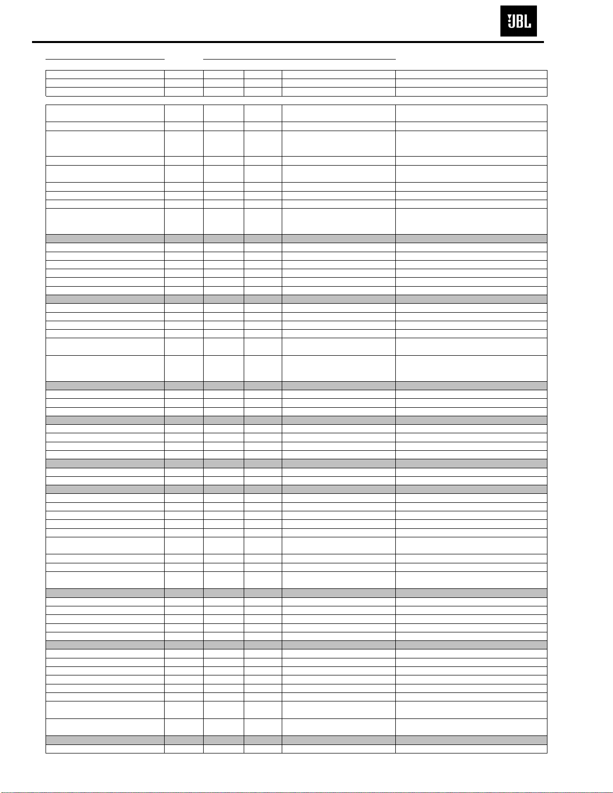
S120PII 300W Powered Sub/ Plate Amp
LINE VOLTAGE Yes/No Hi/Lo Line Nom. Unit Notes
US 120vac/60Hz Yes 108-132 120 Vrms Normal Operation
EU 230vac/50-60Hz Yes 207-264 230 Vrms Normal operation, MOMS required
Parameter Spec Unit
QA Test
Limits Conditions Notes
Amp Section
Type (Class AB, D, other) D n/a n/a
Bridge type amplifier, None of the speaker
terminals must be connected to system GND at
any time.
Load Impedance (speaker) 6 Ohms n/a Nominal
Rated Output Power 275 Watts 220 1 input driven
Limiter prevents continuous power to exceed
220 Watts.
THD @ Rated Power 0.1 % 1 22k filter
THD @ 1 Watt 0.1 % 0.5 22k filter
DC Offset 10 mV-DC 60 @ Speaker Outputs
Damping factor >50 DF 23 Measured at amplifier board
Measured at the speaker cable. 200 Watts,
measured at speaker output terminals located at
the amp board.
Input Sensitivity
Input Frequency 50 Hz 50 Nominal Freq.
L&R 425 mVrms ±2dB To 200 Watts Single input driven
LFE Mode selected 425 mVrms ±2dB To 200 Watts LFE Mode selected, single input driven
Bass Q Input 0.9 Vrms ±2dB To 200 Watts Single input driven
Speaker/Hi Level Input 5.5 Vrms ±2dB To 200 Watts Single input driven
Signal to Noise
SNR-A-Weighted 100 dBA 85 relative to rated power A-Weighting filter
SNR-unweighted 90 dBr 85 relative to rated power 22k filter
SNR rel. 1W-unweighted 65 dBr 60 relative to 1W Output 22k filter
Residual Noise Floor 1 mVrms 2
Volume @max, using RMS reading
DMM/VOM (or A/P)
Residual Noise Floor 1 mVrms
(
max
)
2
Volume @max, w/ A/P Swept
Bandpass Measurement (Line
freq.+ harmonics)
Input Impedance
Line Input (L, R,LFE) 10K ohms n/a Nominal
Speaker/Hi Level Input 10K ohms n/a Nominal
Filters
LP 4th order fixed 50-150 Hz ± 10 2nd order variable and 2nd order fixed
Subsonic filter (HPF) 3rd Order Fixed
LFE Low pass 2nd order Fixed Hz ± 10 LFE input driven only
Limiter
THD at Max. Output Power YES n/a functional Maximum Output Power
Features --
Auto - On -Off switch YES -- functional Refer to ATO section
Phase switch 0-180 deg functional
Volume pot Taper (lin/log) LOG -- functional A Taper
Variable crossover 50-150 Hz YES functional
HP Speaker out functional
HP single order filter 180 Hz @ 8 Ohms, 90 Hz
@ 4 Ohms load
LFE -Normal Select switch YES -- functional Disables LP filter, intended for LFE
BassQ Input YES functional 6.3mm Phono Jack
BassQ Output YES functional Bypass, loop-through - Designed for daisy chain
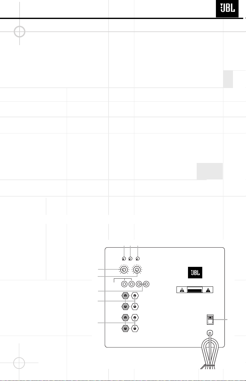
Input Configuration
Line In (L,R) & LFE YES -- functional Dual RCA jack
Bass Q in YES functional 6.3m phono mono Jack
Spkr/Hi Level In YES -- functional Binding post connector L&R
Signal Sensing (ATO)
Auto-Turn-On (yes/no) YES functional Auto - on selection switch in Auto
ATO Input test frequency 50 Hz functional "
ATO Level LFE Input 2 mV functional "
ATO Level Speaker in 50 mV functional "
ATO Level Bass Q input 2 mV functional "
ATO Turn-on time 1 seconds functional
Amp connected and AC on, then
input signal applied
Auto Mute/ Turn-OFF Time 15 minutes 17
T before muting, after signal is
removed
Auto turn of time (T) must be 10 > T < 17
Minutes
Power on Delay time 3 sec. 4 AC Power Applied
S120PII Studio Series
2

Parameter Spec Unit
QA Test
Limits Conditions Notes
Transients/Pops
ATO Transient 5 mV-peak n/a @ Speaker Outputs
Turn-on Transient 50 mV-peak 2v-pp @ Speaker Outputs AC Line cycled from OFF to ON
Turn-off Transient 50 mV-peak 2v-pp @ Speaker Outputs AC Line cycled from ON to OFF
Efficiency
Efficiency 70 % 65 Rated power Nominal Line voltage 120 VAC
Stand-by Input Power 12 Watts 15 @ nom. line voltage
Maximum allowable input power under nominal
Input voltage and frequency, in stand-by mode
(HOT or COLD operation).
Power Cons. @ rated power 400 Watts 400 @ nom. line voltage 250 Watts @ 6.0 Ohms nominal line voltage
Protection
Short Circuit Protection YES functional Direct short at output
Amplifier should resume operation after short
circuit condition removal
Thermal Protection YES functional @1/8 max unclipped Power
Temperature rise in accessible metal parts
should not exceed 35K rise for domestic version
or 30K rise for European versions
DC Offset Protection YES - DC present at Speaker Out leads Relay or crowbar (for driver/fire protection),
Line Fuse Rating
USA-Domestic 4 Amps Type-T or Slo Blo-250 V
EU 2 Amps Type-T or Slo Blo-250 V Internal fuse with UL/SEMKO rated holder
S120PII Studio Series
3

When we designed the
S120PII powered subwoofer,
our goal was to offer the user
the best possible performance
combined with the most
flexible and complete
installation options. Please
look over the following three
examples to determine which
description best matches
your system and follow the
corresponding hookup
instructions.
To use the binding-post
speaker terminals •ª with
bare wire, unscrew the collar
until the pass-through hole in
the center post is visible
under the collar. Insert the
bare end of the wire through
the hole in the post, then
screw the collar back down
until the connection is tight.
The holes in the center of the
collars are intended for
banana-type connectors.
Dolby* Pro Logic* (Non-Digital) –Speaker Level
Use this installation method
for Dolby Pro Logic appli-
cations (not Dolby Digital,
DTS®or other digital
processing), where the
receiver/processor does not
have a subwoofer output or
a volume-controlled preamp
(line-) level output:
If your receiver features bass
management capabilities that
require you to configure your
speaker settings, make sure
to set your left- and right-front
speakers to “LARGE”.
Connect your receiver or
amplifier’s front left and right
speaker terminals to the left
and right terminals on the
subwoofer that are marked
“High Level In”•. Connect
the left and right terminals on
the subwoofer that are
marked “High Level Out”ª
to the corresponding
terminals on the back of your
front left and right speakers.
Connect your receiver or
amplifier’s center, left and
right surround-speaker
terminals to the corre-
sponding terminals on the
back of your center, left and
right surround speakers.
SPEAKER CONNECTION
Right Front
Left Front Center + –
+ – + –
Subwoofer
Right SurroundLeft Surround
+ – + –
+ –
+ –
Left Front Center
+ –
Left Surround
Right Front
+ –
Right Surround
+ –
Receiver
L
R
HIGH
LEVEL
IN
L
R
L
R
HIGH
LEVEL
OUT`
+ –
•
ª
S120PII Studio Series
4

Dolby Pro Logic (Non-Digital) –Line Level
Use this installation method
for Dolby Pro Logic appli-
cations (not Dolby Digital, DTS
or other digital processing),
where the receiver/processor
is equipped with a subwoofer
output or a volume-controlled
preamp (line-) level output:
Use RCA-type patch cords
to connect the line-level
subwoofer outputs on your
receiver or amplifier to the
Line Level inputs ¶on the
subwoofer. IMPORTANT:
Make sure that the LFE toggle
switch ™on the subwoofer is
in the “Normal”position. Do
not use the “LFE”position
with Dolby Pro Logic-only
processors.
Note: If your receiver or
amplifier only has one
subwoofer output jack,
then you may connect the
subwoofer output on your
receiver/preamplifier to either
the left or right Line Level
input ¶on the subwoofer. It
makes no difference which
jack you choose.
Connect each speaker to the
corresponding speaker
terminals on your receiver or
amplifier.
Make sure your receiver or
processor is configured cor-
rectly: Make sure that the sub-
woofer is configured as “On.”
Note for advanced users: If
your receiver/processor has
a built-in low-pass crossover
filter for the subwoofer output,
then the LFE switch ™should
be set to the “LFE”position to
bypass the subwoofer’s
internal crossover.
Subwoofer
Out
RECEIVER
L R
HIGH
LEVEL
IN
HIGH
LEVEL
OUT
L
R
L
R
+ –
IN OUT R L
CROSSOVER
FREQUENCY
BASSQ
(See owner’s
manual
before use)
LINE
LEVEL IN
(For LFE
use R or L)
LEVEL
PHASE AUTO
50Hz
80Hz
180°
0°
LFE
NORMAL
ON
OFF
150Hz MIN MAX
¡
¢
∞
§
¶
•
ª
™£
S120PII Studio Series
5

Dolby Digital or DTS (or Other Digital Surround Mode) Connection
Use this installation method
for Dolby Digital, DTS or other
digital surround processors:
IMPORTANT: Make sure that
the LFE toggle switch ™on
the subwoofer is in the “LFE”
position. Use the Line Level
input jacks ¶for the Low-
Frequency Effects channel.
Connect these jacks to the
LFE output or subwoofer
output on your receiver or
amplifier.
Note: If your receiver or
amplifier has only one
subwoofer output jack,
then you may connect the
subwoofer output on your
receiver/preamplifier to either
the left or right Line Level
input ¶on the subwoofer. It
makes no difference which
jack you choose.
Connect each speaker to the
corresponding speaker
terminals on your receiver or
amplifier.
Make sure that you have
configured your surround
sound processor for
“Subwoofer On”or “LFE On.”
The front left, front right,
center and rear speakers
should be set to “Small”or
“Large”depending on their
size and frequency response.
Consult your receiver’s or
processor’s owner’s manual.
HIGH
LEVEL
IN
HIGH
LEVEL
OUT
L
R
L
R
+ –
IN OUT R L
CROSSOVER
FREQUENCY
BASSQ
(See owner’s
manual
before use)
LINE
LEVEL IN
(For LFE
use R or L)
LEVEL
PHASE AUTO
50Hz
80Hz
180°
0°
LFE
NORMAL
ON
OFF
150Hz MIN MAX
¡
¢
∞
§
¶
•
ª
™£
Subwoofer
Output/LFE
RECEIVER/PREAMPLIFIER
The jacks marked “BassQ”§
are for use with the JBL
BassQ bass equalization
module that will be released
in the near future. The BassQ
will enable you to optimize
your system’s bass response
by equalizing the output of
multiple subwoofers to
best match your listening
environment. DO NOT con-
nect these jacks to any other
device. Do not use the BassQ
jacks §without having first
read the BassQ owner’s
manual.
BassQ
™
Jacks
S120PII Studio Series
6

OPERATION
The S120PII is equipped with
both a master Power switch
‚and an Auto turn-on/turn-
off switch £. In order to
function, the S120PII must
be plugged into an active
electrical outlet (but not an
accessories outlet on another
component of your audio
system such as a receiver),
and the master Power switch
‚must be turned on
(the “•” position).
The Auto turn-on/turn-off
switch £has three positions:
On The subwoofer is on at
all times and ready to
play program material.
Auto As long as no audio
signal is received, the
subwoofer is in Standby
mode to conserve
power, indicated by the
red color of the LEDs on
the front of the unit.
When an audio signal is
sensed, the subwoofer
will switch itself into the
fully On mode and begin
playing the program
material. The LEDs will
turn green. When a
period of about twenty
minutes goes by during
which no signal is
sensed, the S120PII will
return to Standby mode,
indicated by the LEDs
turning red.
Off The subwoofer is off at
all times, even if an
audio signal is present
at its inputs.
If you plan to be away for an
extended time, or if the
subwoofer will not be used,
you may wish to turn off the
master Power switch ‚.
The subwoofer Level Control
∞adjusts the volume of the
subwoofer relative to the rest
of the system. Proper level
adjustment depends on
several variables such as
room size, subwoofer
placement, type of main
speakers and listener position.
Adjust the subwoofer level so
that the volume of the bass
information is pleasing to you.
When using a Dolby Digital/
DTS receiver, adjust the LFE
level on the receiver to 0dB,
and then adjust the subwoofer
Level Control ∞for the
desired amount of bass.
Crossover Adjustments
The Crossover Frequency
Control ¢determines the
highest frequency at
which the
subwoofer reproduces
sounds.
If your main speakers can
comfortably reproduce some
low-frequency sounds, set
this control ¢to a lower
frequency setting, between
50Hz –100Hz. This will
concentrate the subwoofer’s
efforts on the ultradeep bass
sounds required by today’s
films and music. If you are
using smaller bookshelf
speakers that do not extend to
the lower bass frequencies,
set the low-pass Crossover
control ¢to a higher setting,
between 120Hz –150Hz. This
control ¢is not used when the LFE switch ™is in the
“LFE”position.
S120P
II
CAUTION
RISK OF ELECTRIC SHOCK
DO NOT OPEN
WARNING: TO REDUCE THE RISK OF FIRE OR ELECTRIC SHOCK,
DO NOT EXPOSE THIS APPLIANCE TO RAIN OR MOISTURE.
AVERTISSEMENT: POUR PRÉVENIR LES RISQUES D’INCENDIE OU
DE CHOC ÉLECTRIQUE ÉVITER D’EXPOSER CET APPAREIL A LA
PLUIE OU A L’HUMIDITÉ.
ON
OFF
HIGH
LEVEL
IN
HIGH
LEVEL
OUT
L
R
L
R
+ –
IN OUT R L
CROSSOVER
FREQUENCY
LINE
LEVEL IN
(For LFE
use R or L)
LEVEL
PHASE AUTO
BASSQ
(See owner’s
manual
before use)
50Hz
80Hz
180°
0°
LFE
NORMAL
ON
OFF
150Hz MIN MAX
¡
¢
∞
¶
•
ª
™£
‚
§
Level Control
Power
S120PII Studio Series
7

TROUBLESHOOTING
If you used the High Level
(speaker) inputs •and there
is no sound from any of the
speakers:
•
Check that receiver/amplifier
is on and a source is playing.
•Check that powered
subwoofer is plugged into
an active electrical outlet
and is switched on £‚.
•Check all wires and
connections between
receiver/amplifier and
speakers. Make sure all wires
are connected. Make sure
none of the speaker wires
are frayed, cut or punctured.
Make sure no wires are
touching other wires or
terminals and creating a
short circuit.
•Review proper operation
of your receiver/amplifier.
If there is low (or no) bass
output:
•Make sure the connections
to the left and right “Speaker
Inputs”•have the correct
polarity (+ and –).
•Make sure that the
subwoofer is plugged into an
active electrical outlet and
that both power switches
are on £‚.
•Adjust the Crossover point
¢.
•Flip the Phase Control
switch ¡to the opposite
position.
•If you are using a Dolby
Digital/DTS receiver or
processor, make sure that the
subwoofer adjustments on
the receiver/processor are
set up correctly. When using
the S120PII’s Speaker Level
inputs •, you should set your
receiver to configure the
main left and right speakers
as “LARGE”.
•Slowly turn the Level
Control ∞clockwise until
you begin to hear the desired
amount of bass.
If you used the Line Level
inputs ¶and there is no
sound from the subwoofer:
•
Check that receiver/amplifier
is on and a source is playing.
•Check that powered
subwoofer is plugged into an
active electrical outlet and
that both Power switches
are on £‚.
•Check all wires and con-
nections between receiver/
amplifier and subwoofer.
Make sure all wires are
connected. Make sure none
of the wires are frayed, cut
or punctured.
•Review proper operation of
your receiver/amplifier.
•Slowly turn the Level
Control ∞clockwise until
you begin to hear the desired
amount of bass.
•Make sure that you have
configured your receiver/
processor so that the
subwoofer/LFE output is on.
Phase Control
The Phase Control ¡
determines whether the
subwoofer’s piston-like action
moves in and out in phase
with the main speakers or
opposite the main speakers.
There is no correct or
incorrect setting. Proper
phase adjustment depends on
several variables such as
subwoofer placement and
listener position. Adjust the
Phase switch ¡to maximize
bass output at the listening
position.
Remember, every system,
room and listener is different.
There are no right or wrong
settings; this switch ¡offers
the added flexibility to adjust
your subwoofer for optimum
performance for your specific
listening conditions without
having to move your speakers.
If at some time in the future
you happen to rearrange your
listening room and move
your speakers, you should
experiment with the Phase
switch ¡in both positions,
and leave it in the position
that maximizes bass
performance.
S120PII Studio Series
8

Service Bulletin
Service Bulletin JBL2003-06 - April 2003 This is considered a Minor repair
To: All JBL Service Centers
Model: S120PII
Subject: Distortion When Coming Out Of Standby
In the event you receive an S120PII subwoofer with the complaint “There is a brief chirping sound, or
short oscillation that occurs when the unit is in the AUTO mode, in Standby, when it’s triggered ON
with a music signal”, follow the procedure below to correct this condition:
Synopsis: Replace D60 (RLS4148 diode) with a 3.6V Zener Diode; add new Resistor.
1) Remove the amplifier assembly from the subwoofer cabinet (12 Phillips screws).
2) Remove the Plastic Amp Cover from the faceplate (4 Phillips screws).
3) The area of concern is on the Class D Driver PCB (Small Upright PCB on the MAIN AMP PCB). A
long, thin, soldering iron tip is recommended. Care must be taken not to damage surrounding
components, like large inductor pair L8.
4) Locate, remove D60 (RLS4148 diode); replace with a 3.6V zener diode, JBL Part# ZMM5227BCT-ND.
When replacing D60 the polarity of the new (zener) diode should be reversed.
5) Add new 27KΩresistor, JBL Part# 299-27K, to the indicated connections. (This component,
electrically, will be in parallel with R37, reducing its value to <22KΩ). Assure the leads do not come
into contact with any other connections; insulate the leads if necessary.
6) Replace amp cover and return amplifer assembly to cabinet.
7) Test the subwoofer to assure the distortion is no longer present.
9

S120PII Studio Series
10
S120PII BLOCK DIAGRAM

12" Woofer
338008-001
Front Grille
338007-001
(8) Screws PB, HXS. #8 x .75"
903802-012
(4) Rubber Foot Assembly
338037-001
Top Plate
337898-001 Port Tube
337859-001
Amplifier Assembly
Not for Sale
Top Plate Gasket
338012-001
LED Indicator Assembly
335650-001
(4) Grille Retainers
333249-001
(12) Screws
PB, HXS. #8 x .75"
903802-012
S120PII
Studio™Series
S120PII Studio Series
EXPLODED VIEW
11

S120PII Test Set Up and Procedure
SYSTEM AURAL SWEEP TEST
Equipment needed:
• Function/signal generator/sweep generator
• Integrated Amplifier
• Multimeter
• Speaker cables
• RCA phono cables (pair)
General Unit Function (UUT = Unit Under Test)
Switches/knobs on the amplifier faceplate:
Crossover Frequency Adjust full CW (150Hz)
Phase switch – either position
Normal/LFE switch – Normal
Auto On/Off - either position
1. From the signal generator, Connect both right and left line level inputs (RCA jacks) – to signal generator and
UUT. Use Y-cable if necessary from mono source.
2. On the amplifier, turn the LEVEL control full Counterclockwise (Min).
3. Turn on generator, adjust to 100mV, 50 Hz.
4. Plug in UUT; turn the power switch ON. Turn LEVEL control full Clockwise (Max).
5. LED’s (top of UUT) should now be Green; immediate bass response should be heard and felt from port tube
opening.
6. Turn LEVEL control full Counterclockwise (Min). Turn power switch OFF.
7. Connect one pair of speaker cables to one set (either R or L) of the Speaker Input terminals on UUT. Cables
should be connected to an integrated amplifier fed by the signal generator.
8. Turn on signal generator and adjust so that speaker level output at the amplifier is 2.5V, 50 Hz.
9. Turn power switch ON; turn LEVEL control full Clockwise (Max).
10. Bass response should be heard and felt from port tube opening.
Sweep Function
1. Follow steps 1-5 above, using a sweep generator as a signal source.
2. Sweep generator from 20Hz to 1kHz. Listen to the cabinet and drivers for any rattles, clicks, buzzes or
any other noises. If any unusual noises are heard, remove woofer and test.
Driver Function (Woofer)
1. Remove woofer from cabinet; detach + and - wire clips.
2. Check DC resistance of woofer; it should be 4.4 ohms±10%.
3. Connect a pair of speaker cables to driver terminals. Cables should be connected to an integrated
amplifier fed by a signal generator. Turn on generator and adjust so that speaker level output is 5.0V.
4. Sweep generator from 20Hz to 1kHz. Listen to driver for any rubbing, buzzing, or other unusual noises.
12

S120PII ELECTRICAL PARTS LIST
Part Number Qt
y
Descri
p
tion Reference Desi
g
nato
r
Amplifier PCB
Resistors
021-100401-020 1 Metal oxide film resistor 1K 1W J FK TYPE R173
021-620303-020 2 Metal oxide film resistor 620R 3WS J 8x20 KINK R76,78
022-005105-020 1 cement resistor PN:SQM 0R05 5W J 25x13 R2
0024-00098-120 1 SMD resistor 0R 1/8W J 0805 TAPING R8
024-100498-120 2 SMD resistor 1K 1/8W J 0805 TAPING R110,169
024-100598-120 14 SMD resistor 10K 1/8W J 0805 TAPING R5,7,16,118,121,122,125,126,
128,138,165,170,168,139
024-100698-120 2 SMD resistor 100K 1/8W J 0805 TAPING R15,120
024-130498-100 1 SMD resistor 1K3 1/8W F 0805 TAPING R119
024-160598-100 2 SMD resistor 16K 1/8W F 0805 TAPING R13,13B
024-220498-121 1 SMD resistor 2K2 1/8W J 0805 TAPING R17
024-220598-120 1 SMD resistor 22K 1/8W J 0805 TAPING R127
024-330498-120 2 SMD resistor 3K3 1/8W J 0805 TAPING R77,79
024-330598-120 5 SMD resistor 33K 1/8W J 0805 TAPING R4,6,14,60,60B
024-470298-120 4 SMD resistor 47R 1/8W J 0805 TAPING R24,25,26,27
024-470398-120 4 SMD resistor 470R 1/8W J 0805 TAPING R145,155,177,186
024-470598-120 2 SMD resistor 47K 1/8W J 0805 TAPING R3,171
024-510498-120 5 SMD resistor 5K1 1/8W J 0805 TAPING R48A,48B,48C,48D,48E
024-910498-120 1 SMD resistor 9K1 1/8W J 0805 TAPING R63
025-010300-000 1 Thermistor TSE-103 K L:50mm TH1
Capacitors
031-100184-100 2 SMD capacitor 0u01/250V K 0805 X7R TAPING C104,119
031-100244-100 2 SMD ceramic capacitor 0u01/50V K 0805 X7R TAPING C27,28
031-100344-100 6 SMD capacitor 0u1/50V K 0805 X7R TAPING C10,69,112,115,135,138
031-100384-100R 2 SMD capacitor 0u1/250V K 1206 X7R TAPING C5,6
031-470144-101 1 SMD capacitor 0u0047/50V K 0805 X7R TAPING C1G1
032-100484-200 3 END PE capacitor 1uF/250V K P:15mm C37,39,30
033-330444-270 2 NPE capacitor 3u3/50V K10 (R)8x13 SBE C114,137
033-680464-270 2 NPE capacitor 6u8/100V K10 (R)1020 GNE C113,136
034-100614-300 1 Electrolytic capacitor 100uF/16V M (R)0611 P:2.5 C8
034-100625-300 1 Electrolytic capacitor 100uF/25V M (R)6.3x11 P:5 C62
034-100695-300 1 Electrolytic capacitor 100uF/63V M (R)1012 P:5 TAPING C142
034-100895-204 2 Electrolytic capacitor 10000uF/63V M R30x51 85 C1,4
034-220525-300 2 Electrolytic capacitor 22uF/25V M (R) 5x11 P:2.5 C25,26
034-330625-300 2 Electrolytic capacitor 330uF/25V M (R)1013 P:5 C11,100
034-470415-300 1 Electrolytic capacitor 4u7/50V M (R)0511 P:2.0 C7
S120PII Studio Series
13

Part Number Qt
y
Descri
p
tion Reference Desi
g
nato
r
Semiconductors
051-000600-100 1 Transistor NPN MPSW06RLRA TO-92 TAPING Q6
051-005600-100 1 Transistor NPN MPSW56RLRA MPQ TO-92 TAPING Q8
051-290700-100 4 Transistor P2N2907A TO-92 TAPING Q12,14,16,18
051-540101-000 1 Transistor PNP 2N5401 TO-92 TAPING Q3
051-640000-100 4 MOSFET N-Channel IRF640 TO-220 Q11,13,15,17
052-400080-000 1 Diode Bridge PN:RS804 400V,8A BR1
053-257400-100 1 IC;DIP 8P LM2574 HVN-15V 0.5A Step-Down Voltage Regulator U6
054-000100-100 6 SMD DIODE ES1D 200V,1A,35ns TAPING D1,23,37,40,44,47
054-001002-100 1 SMD ZENER DIODE 10V SOT-23 BZX84C10 TAPING D32
054-001501-100 2 SMD ZENER DIODE 15V SOT-23 BZX84C15 TAPING D2,3
054-033904-100 3 SMD TR (MOTOROLA) MMBT3904LT1 SOT23 TAPING Q25,28,29
054-033906-100 3 SMD TR (MOTOROLA) MMBT3906LT1 SOT23 TAPING Q26,27,30
054-050601-100 1 SMD ZENER DIODE 5.6V SOT-23 BZX84C5V6 TAPING D30
054-414803-100 14 SMD diode LL4148 TAPING D4-6,13,14,21,22,31,33,34,
38,41,45,48
054-540100-100 1 SMD PNP transistor MMBT5401 LT1 TAPING Q1
054-555100-100 1 SMD NPN Transistor MMBT5551 LT1 TAPING Q2
Miscellaneous
072-040039-000 1 Terminal (PCB TYPE) PC205 (t=0.8m/m) T205MA T2
072-040064-000 2 Terminal (PCB TYPE) PC250(t=0.8),T250MA T1,TER6
072-040096-000 2 Terminal T187MA(PCB TYPE
)
(t=0.8mm) PC187(0.8) TER5,TER7
072-040250-000 1 Connector 7 PIN JS-1001-7 P:2.5mm P1
073-111003-000 1 Shorting strap 54.9x13.6x1m/m J7
073-111004-000 2 Shorting strap 29.5x12.4x0.8m/m J4,9
074-300018-000 1 Relay PN:943-1C-48D RLY1
043-300101-000 2 Inductor 30uH YT-10033 L9,10
043-560200-000 1 Inductor 56uH YT-10779 L12
043-700100-000 1 Inductor 70uHx2 YT-10024 L8
043-820300-000 1 Inductor 820uH YT-10034 L1
044-100100-000 2 SMD Ferrite bead PN:321611 600R/100MHz 1206 FB1,FB2
CLASS D DRIVER PCB (Small Upright PCB on Amp PCB)
Resistors
024-000098-120 4 SMD resistor 0R 1/8W J 0805 TAPING R313,314,318,320
024-100298-120 4 SMD resistor 10R 1/8W J 0805 TAPING R89,90,140,150
024-100498-120 10 SMD resistor 1K 1/8W J 0805 TAPING R81,85,96,97,131,137,142,
147,162,179
024-100598-120 12 SMD resistor 10K 1/8W J 0805 TAPING R75,82,83,92,98,132,133,
148,163,164,181,156
S120PII Studio Series
14

Part Number Qt
y
Descri
p
tion Reference Desi
g
nato
r
024-100698-120 1 SMD resistor 100K 1/8W J 0805 TAPING R37
024-110598-120 2 SMD resistor 11K 1/8W J 0805 TAPING R74,99
024-200598-120 2 SMD resistor 20K 1/8W J 0805 TAPING R95,141
024-220398-120 2 SMD resistor 220R 1/8W J 0805 TAPING R136,167
024-220498-121 1 SMD resistor 2K2 1/8W J 0805 TAPING R134
024-220798-120 2 SMD resistor 2M2 1/8W J 0805 TAPING R87,93
024-270498-120 3 SMD resistor 2K7 1/8W J 0805 TAPING R80,84,157
024-390498-120 2 SMD resistor 3K9 1/8W J 0805 TAPING R130,161
024-390598-120 2 SMD resistor 39K 1/8W J 0805 TAPING R86,94
024-470398-120 1 SMD resistor 470R 1/8W J 0805 TAPING R91
024-470498-120 6 SMD resistor 4K7 1/8W J 0805 TAPING R151-153,183,34,36
024-470598-120 1 SMD resistor 47K 1/8W J 0805 TAPING R35
024-470698-120 2 SMD resistor 470K 1/8W J 0805 TAPING R32,33
024-560598-120 1 SMD resistor 56K 1/8W J 0805 TAPING R38
024-680498-120 2 SMD resistor 6.8K 1/8W J 0805 TAPING R135,166
Capacitors
031-100244-100 4 SMD ceramic capacitor 0u01/50V K 0805 X7R TAPING C108,118,131,140
031-100343-100 2 SMD capacitor 100pF/50V J 0805 NPO TAPING C81,84
031-100344-100 6 SMD capacitor 0u1/50V K 0805 X7R TAPING C75-78,82,85
031-180344-100 2 SMD capacitor 0u18/50V K 0805 X7R TAPING C80,83
031-470244-102 4 SMD capacitor 0u047/50V K 0805 X7R TAPING C93,94,101,124
031-560243-100 4 SMD capacitor 56pF/50V J 0805 NPO TAPING C92,102,105,125
031-560343-102 1 SMD capacitor 560pF/50V J 0805 NPO TAPING C79
034-100625-303 1 Electrolytic capacitor 100uF/25V M (R) P:2.5 TAPING C117
034-100715-202 2 Electrolytic capacitor 1000uF/16V M (R) 10x17 P:5 C109,132
034-330615-301 1 Electrolytic capacitor 330uF/16V M (R)0812 P:3.5 C32
Semiconductors
051-000600-100 1 NPN transistor MPSW06RLRA TO-92 TAPING Q31
051-222200-100 2 NPN transistor PN:MPS2222ARLRA TO-92 TAPING Q20,22
051-555100-000 2 NPN transistor 2N5551 TO-92 TAPING Q21,23
053-211100-000 2 IC;DIP PN:IR2111 HALF-BRIDGE DRIVER U7,8
054-000100-100 2 SMD DIODE ES1D 200V,1A,35ns TAPING D35,43
054-001002-100 2 SMD ZENER DIODE 10V SOT-23 BZX84C10 TAPING D42,49
054-007200-100 2 SMD IC TL072CDR SO-8 (TI) TAPING U9,10
054-033906-100 2 SMD TR (MOTOROLA) MMBT3906LT1 SOT23 TAPING Q34,35
054-050601-100 2 SMD ZENER DIODE 5.6V SOT-23 BZX84C5V6 TAPING Z7,8
054-414803-100 6 SMD Diode LL4148 TAPING D36,39,46,52,60,61
054-540100-100 2 SMD PNP transistor MMBT5401 LT1 TAPING Q33,40
054-555100-100 1 SMD NPN transistor MMBT5551 LT1 TAPING Q32
S120PII Studio Series
15

Part Number Qt
y
Descri
p
tion Reference Desi
g
nato
r
Miscellaneous
072-040229-000 1 Header, Right Angle PN:211-107-000-400 7PIN PIN2
072-040230-000 1 Header, Right Angle PN:211-111-000-400 11PIN PIN1
Pre/Input PCB
Resistors
021-121598-100 1 metal film resistor 12K1 1/8W F TAPING R204
021-121698-100 1 metal film resistor 121K 1/8W F TAPING R214
021-301498-100 1 metal film resistor 3K01 1/8W F TAPING R220
021-680498-100 2 metal film resistor 6K8 1/8W F TAPING R208,209
024-000098-120 4 SMD resistor 0R 1/8W J 0805 TAPING R301,302,303,309
024-100398-120 1 SMD resistor 100R 1/8W J 0805 TAPING R249
024-100498-120 1 SMD resistor 1K 1/8W J 0805 TAPING R238
024-100598-120 17 SMD resistor 10K 1/8W J 0805 TAPING R202,205,222,225,227,229,
234,235,236,239,252,253,
254,257,217,262,228
024-100698-100 4 SMD resistor 100K 1/8W F 0805 TAPING R219,218,200,201
024-137698-100 1 SMD resistor 137K 1/8W F 0805 TAPING R213
024-150498-120 2 SMD resistor 1K5 1/8W J 0805 TAPING R251,255
024-150598-120 1 SMD resistor 15K 1/8W J 0805 TAPING R223
024-200598-120 1 SMD resistor 20K 1/8W J 0805 TAPING R256
024-220798-120 1 SMD resistor 2M2 1/8W J 0805 TAPING R244
024-240598-120 1 SMD resistor 24K 1/8W J 0805 TAPING R224
024-270498-120 1 SMD resistor 2K7 1/8W J 0805 TAPING R237
024-300398-120 1 SMD resistor 300R 1/8W J 0805 TAPING R258
024-300598-120 1 SMD resistor 30K 1/8W J 0805 TAPING R260
024-330498-100 4 SMD resistor 3K3 1/8W F 0805 TAPING R203,215,240,247
024-330598-120 1 SMD resistor 33K 1/8W J 0805 TAPING R212
024-453598-100 1 SMD resistor 45K3 1/8W F 0805 TAPING R207
024-470498-120 2 SMD resistor 4K7 1/8W J 0805 TAPING R230,210
024-470698-120 1 SMD resistor 470K 1/8W J 0805 TAPING R259
024-470798-120 1 SMD resistor 4.7M 1/8W J 0805 TAPING R243
024-510398-120 1 SMD resistor 510R 1/8W J 0805 TAPING R261
024-680598-120 2 SMD resistor 68K 1/8W J 0805 TAPING R206,250
024-750798-120 1 SMD resistor 7M5 1/8W J 0805 TAPING R241
024-820598-120 1 SMD resistor 82K 1/8W J 0805 TAPING R263
Capacitors
031-100244-100 3 SMD capacitor 0u01/50V K 0805 X7R TAPING C12,13,224
S120PII Studio Series
16

Part Number Qt
y
Descri
p
tion Reference Desi
g
nato
r
031-100343-100 2 SMD capacitor 100pF/50V J 0805 NPO TAPING C222,204
031-100344-100 7 SMD capacitor 0u1/50V K 0805 X7R TAPING C227,232,233,229,234,235,230
031-220244-101U 1 SMD capacitor 0u022/50V K 0805 X7R TAPING C202
031-220344-100 2 SMD capacitor 220pF/50V J 0805 NPO TAPING C210,200
031-470144-101 1 SMD capacitor 0u0047/50V K 0805 X7R TAPING C219
031-680144-100 1 SMD capacitor 0u0068/50V K 0805 X7R TAPING C212
033-200695-300 2 NP Electrolytic capacitor 200u/63V M (R)1326 P:5 C205,203
034-100525-301 1 Electrolytic capacitor 10uF/25V M (R) P:2 TAPING C220
034-220525-300 4 Electrolytic capacitor 22uF/25V M (R) 5x11 P:2.5 C15,14,223,225
034-220625-300 1 Electrolytic capacitor 220uF/25V M (R)0812 P:5 TAPING C221
038-100363-300 2 MPE capacitor P:5 0u1/100V J TAPING C201,209
038-150393-300 2 MPE capacitor 0u15/63V J P:5 TAPING C208,207
038-680393-300 1 MPE capacitor 0u68/63V J P:5 TAPING C214
Semiconductors
054-007200-100 6 SMD IC TL072CDR SO-8 (TI) TAPING U202,203,204,200,201,205
054-033904-100 2 SMD TR (MOTOROLA) MMBT3904LT1 SOT23 TAPING Q203,204
054-050601-100 1 SMD ZENER DIODE 5.6V SOT-23 BZX84C5V6 TAPING D210
054-211400-100 1 SMD NPN Transistor DTC114EK SMT3 TAPING Q202
054-414803-100 12 SMD diode LL4148 TAPING D215,212,209,207,205,200,
201,202,203,204,216,217
Miscellaneous
072-040008-000 1 4P terminal housing JS-1001-04 P4
072-040169-000 1 Connector 2 PIN JS-1001-2 P:2.5mm CONN3
072-040250-000 1 Connector 7 PIN JS-1001-7 P:2.5mm P2
Copper wire Jumper In lieu of C206
Phone Jack PCB
024-000098-120 2 SMD resistor 0R 1/8W J 0805 TAPING R305,307
024-620398-120 2 SMD resistor 620R 1/8W J 0805 TAPING R221,226
031-220344-100 2 SMD capacitor 220pF/50V J 0805 NPO TAPING C215,216
072-010100-000 2 Phone Jack PN:JY-6313-01-340 J206,207
072-010101-000 1 RCA Jack PN:RJ-1031-10-0300A J205
072-040251-000 1 Header Right angle PN:211-104-000-400 4PIN
Toggle Switch PCB
031-470144-101 1 SMD capacitor 0u0047/50V K 0805 X7R TAPING C2G1
072-040252-000 1 HEADER Right Angle PN:211-109-000-400 9PIN
073-010021-000 1 Screw base PN:PCB-2(M3) 4PIN T3
074-030002-000 2 Toggle Switch P/N L101 SW201,200
S120PII Studio Series
17

Part Number Qt
y
Descri
p
tion Reference Desi
g
nato
r
074-030018-000 1 Toggle Switch PN:L103-T2-B4 SW202
Control Pot PCB
021-301498-100 2 metal film resistor 3K01 1/8W F TAPING R231,232
026-200595-269 1 VR 20Kx2 FREQ PN:RD163121R03D-20KBx2(EJ) R233
026-500595-254 1 VR 50K LEVEL P/N:RK163111R405-EJ R216
038-100363-300 2 MPE capacitor P:5 0u1/100V J TAPING C218,213
072-040251-000 1 Header, Right Angle PN:211-104-000-400 4PIN
072-040253-000 1 Header, Right Angle PN:211-103-000-400 3PIN
Fuse PCB
039-220180-100 1 X2 capacitor 0u22/250V 18x16.5x8.5mm PN:XG275M224VHS2 CXAC1
043-324300-000 1 Inductor 324uH YT-10778 L13
072-040064-000 1 Terminal (PCB TYPE) PC250(t=0.8),T250MA TER4
072-040096-000 3 Terminal T187MA(PCB TYPE) (t=0.8mm) PC187(0.8) TER1,2,3
073-050001-000 2 Fuse Clip P/N:CFFH1206 F1B1
091-000128-000 1 AC Line Fuse T4A/250V 5x20mm F1
Miscellaneous
008-060302-032 4 Gasket 28x20mm t=5mm C4305 For X'FORMER
008-061215-000 1 Gasket 12x15 t=5mm CR For Thermistor
008-062001-000 4 Gasket 196x10mm t=1mm COVER(Front)x2,COVER(Rear)x2
008-063001-000 4 Gasket 320x10mm t=1mm COVER(front)x2,COVER(Rear)x2
042-014107-0011 Transformer 120V/60Hz EI-125 YT-9313-1 Power
061-015002-000 2 Knob P/N 446077(18teeth)D:15.1 H:14.5 Knob (P 400W) w/white indicator
061-100016-000 3 Nylon partition PN:BCMS-8 L=8mm NYLON 66(UL) For Power PCB
061-314002-000 2 Strain Relief P/N SB4F-2 For PANEL,COVER
061-700035-000 2 Insulation sheet PN:TO-220AWO For Q11,15
061-700044-000 2 Mica 13x18mm TO-220 For Q13,17
063-010010-000 5 Bracket for Transistor P/N:TRK-2
063-332100-000 1 Front faceplate 12.83"x8.33" t=0.0984"
063-332101-000 1 Plastic Amp Cover 12.83"x8.33"x3.93" ABS 94V0
070-040011-210 5 screw PMS;M3x10mm BLK(H) w/dble WASHER For TRx5
070-040811-308 1 screw M3x8mm zinc white For Terminal
070-040866-504 5 screw #6-32x1/4" zinc white For PCB
070-040866-516 5 screw #6-32x5/16" zinc white For Bracket
070-040886-803 4 screw 8#-32x1/2" zinc white For Transformer
070-540810-808 3 screw 3x8 zinc white For Power PCB
070-900811-312 9 screw PTS-4;3x12 zinc white For RCAx1,BPx8
070-940831-412 4 screw 4x12mm zinc white For COVERx4
S120PII Studio Series
18

Part Number Qt
y
Descri
p
tion Reference Desi
g
nato
r
071-060280-500 4 nut washer 8#-32 zinc plated 8.5 t=3m/m For Transformer
071-100606-060 2 flat washer PN:WS3-2 OD=6 ID=3.t=2mm nylon For Q11,Q13
073-014044-000 1 Bracket 6.64"x3.50"x3.20" SPCC cadium plated
074-020018-000 1 Rocker Switch (Power) PN:RF1003-BB4-0 SW4
082-022241-000 1 Wire #22 UL1007 L=410mm blk/wht XH2P+HWAFER
082-072620-000 1 Wire #26 UL1007 L=200mm XH7Px2 blk+whtx6
086-021836-000 1 Double insulated cable SPT-2 #18 12feet +T187 Power cord
181-911600-158 1 Wire #16AWG UL1007 blk L=720mm
181-911622-148 1 Wire #16AWG UL1007 red L=720
181-921600-000 1 BLKWire #16 UL1015 both ends T187 trans sleeve L:140mm
181-921699-000 1 WHT Wire #16 UL1015 both ends T187 transp sleeve L:160mm
LED Assy On the Cabinet
050-011700-000 2 LED red/green P/N:L-117EGW LED1,2
083-022204-000 1 UL1007 #22 white, blk XH2P+5TT
114-060200-000 1 Wire 35.6x16.8x1.6mm FR-4 dble side thru hole
19
Other manuals for Studio S120PII
1
Table of contents
Other JBL Subwoofer manuals