JCM GLOBAL Taiko PUB-7 User manual

Part No. 960-100919R_Rev. 1 © 2017 JCMAmerican Corporation
2
Taiko™ Banknote Validator JCM Training Overview March, 2017
Page
Taiko™ Banknote Validator
Table of Contents
Overview.................................................................................. 3
Component Part Locations .......................................................................3
Taiko (PUB-7/11) DIP Switch Designations............................. 4
Enabling Taiko Features.......................................................... 5
Denomination Settings..............................................................................5
Accept Mode.......................................................................................................5
Inhibit Mode ........................................................................................................5
LED Pattern Selection Settings.................................................................6
Cleaning the Unit.......................................................................................7
Calibration ............................................................................... 8
Entering Test Mode.................................................................. 9
Functional Tests........................................................................................9
Aging Test Error Codes...........................................................................11
Error Codes - Bill Acceptance.................................................................13
Sensor Locations ....................................................................................15
Downloading Software........................................................... 16
PC Software Loading..............................................................................16
BlueWave 2.0™ Software Update...........................................................16
Cloning Software.....................................................................................17
Malfunction Errors ................................................................. 18
Red LED Error Code Definitions.............................................................18
Taiko Unit Parts List............................................................... 19
Personal Notes and Comments............................................. 20

Part No. 960-100919R_Rev. 1 © 2017 JCMAmerican Corporation
3
Lecture Notes
Taiko™ Banknote Validator JCM Training Overview March, 2017
OVERVIEW
This training course addresses the following JCM Taiko™Series versions:
C
OMPONENT
P
ART
L
OCATIONS
Table 1 Various Taiko (PUB-7/11) Version Sensor Types
Unit Currency Sensors Available
PUB-7 Optical, Transparency and Reflective
PUB-11 Optical, Transparency, Reflective and Magnetic
Figure 1 Taiko (PUB-7/11) Primary Component Parts
A. Bezel
B. Bezel LED
C. Upper Guide Lid
D. Lower Guide Lid
E. Lower Lid Lock/Release Buttons
F. Banknote Insertion Slot
G. Banknote Exit Slot
H. Interface Connector
I. Maintenance Connector
J. Faceplate Installation Guide Pin
K. Upper Lid Open Close Button
L. Interface Connector
M. DIP Switch Block

Part No. 960-100919R_Rev. 1 © 2017 JCMAmerican Corporation
4
March, 2017 JCM Training Overview Taiko™ Banknote Validator
TAIKO (PUB-7/11) DIP SWITCH DESIGNATIONS
The Taiko™Unit can be configured for various Communications Standards
and Protocols. Refer to the Taiko™Series (PUB-7/11) Operation and Mainte-
nance Manual (JAC Part No. 960-100175R), Tables 2-5, 2-6 and 2-7 for locat-
ing specific Connector Pin designations for either Serial/MDB, CC-Talk or
Pulse communication Protocols respectively.
Communications Protocols are selected via DIP Switch settings (Table 2).
Table 2 Typical Taiko DIP Switch Block Settings
SW No. DIP Switch Position Setting
1OFF Normal operation
ON Test Mode (Setting Mode)
2OFF 1-time scan (without validation retry)
ON 2-time scan mode (with validation retry)
3OFF When Pulse I/F Mode, depends on enable/disable signal.
ON When Pulse I/F Mode, always enabled.
4OFF 1 time Spin Mode (1 Drum Rotation Cycle)
ON 5 time Spin Mode (5 Drum Rotation Cycles - Anti-Fishing Prevention)
5Serial I/F Mode (DIP Switch 8 OFF) Pulse I/F Mode (DIP Switch 8 ON)
6
7
8OFF Serial I/F Mode (Selected by DIP Switches 6 and 7)
ON Pulse I/F Mode
NOTE: Always check the current Taiko™ Software Data Sheets to
verify the proper DIP Switch settings required for your particular Unit.
ON
OFF
SW5 PULSE WIDTH
OFF 50ms/300ms
ON 50ms/50ms
SW6 SW7 I/F Setting
OFF OFF ID-003
ON OFF ID-0D3
OFF ON ID-0E3 (without
Encryption)
ON ON ID-0E3 (with
Encryption)
SW6 SW7 Number of PULSE
OFF OFF 1 Dollar = 1 Pulse
OFF ON 1 Dollar = 4 Pulses
ON OFF 1 Dollar = 10 Pulses
ON ON 1 Dollar = 20 Pulses

Part No. 960-100919R_Rev. 1 © 2017 JCMAmerican Corporation
5
Taiko™ Banknote Validator JCM Training Overview March, 2017
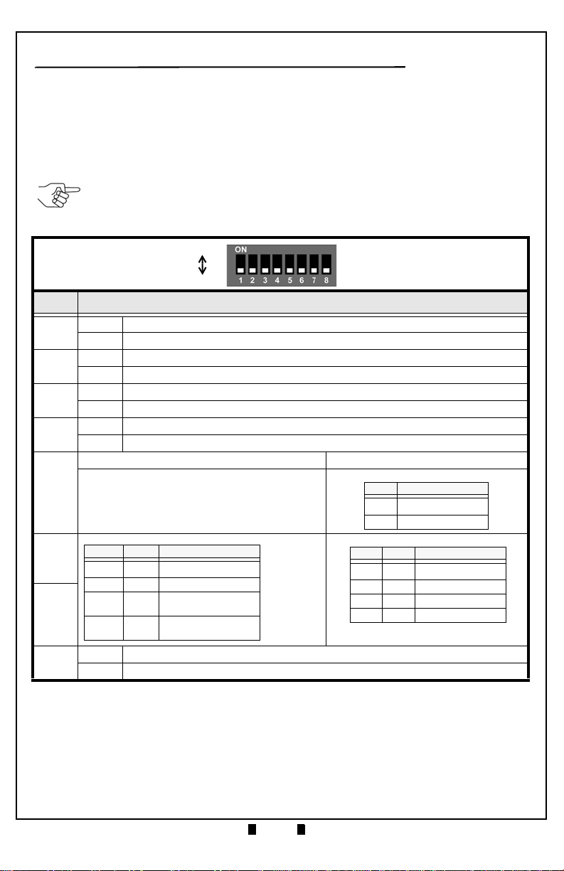
ENABLING TAIKO FEATURES
The Taiko™setting for Banknote Acceptance and Front Panel LED Color
Pattern oscillations can be changed using DIP Switch enable routines.
D
ENOMINATION
S
ETTINGS
Specific Banknote denominations can either be accepted or rejected. To enable
the acceptance of particular Banknote denominations, use the following
“Accept Mode” Procedure.
Accept Mode
To enable Banknote acceptance, proceed as follows:
1. Remove power from the Taiko™Unit.
2. Set DIP Switches #1 and #6 to ON.
3. Reapply power to the Unit.
4. After the Front Panel LED flashes WHITE, turn DIP Switch #1 OFF.
The BLUE LED will begin to flash.
5. Insert the Banknote to be accepted.
The Banknote will be read and held in place, and the BLUE LED will be ON
(Steady). The Banknote will then be returned, and the BLUE LED will flash.
Acceptance of the selected Banknote denomination is now enabled.
6. Continue to insert each desired Banknote denomination that is to be accepted.
7. When done, remove power from the Taiko™Unit, reset the DIP Switches to
their normal operating positions, and reapply power to the Unit.
To disable the acceptance of particular Banknote denominations, use the
following “Inhibit Mode” Procedure. The default setting is to accept all
Banknotes programmed in the existing operating software.
Inhibit Mode
To allow the Taiko™Unit to reject or not accept a particular Banknote denom-
ination, proceed as follows:
1. Remove power from the Taiko™Unit.
2. Set DIP Switches #1, #6 and #7 to ON.
3. Reapply power to the Unit.
4. When the WHITE LED flashes, turn DIP Switch #1 OFF.
5. When the BLUE LED flashes, then flashes ORANGE, insert the Banknote that
is to be disabled or not to accepted.
The ORANGE LED will light steady while the Banknote is accepted and
returned. This denomination of Banknote is now inhibited from being accepted.
6. Continue inserting each specific denomination Banknote to be inhibited.
7. When done, remove power from the Taiko™Unit, reset the DIP Switches to
their normal operating positions, and reapply power to the Unit.

Part No. 960-100919R_Rev. 1 © 2017 JCMAmerican Corporation
6
March, 2017 JCM Training Overview Taiko™ Banknote Validator
Lecture Notes
LED P
ATTERN
S
ELECTION
S
ETTINGS
The Bezel LED oscillating Pattern Color can be changed to oscillate between
two preset changing Color patterns.
To select and set Color Pattern #1, proceed as follows:
1. Remove power from the Taiko™Unit.
2. Set DIP Switches #1, #2 and #7 to ON.
3. Reapply power to the Taiko™Unit.
4. When the White LED begins to flash, turn DIP Switch #1 OFF.
The selected pattern is now set.
5. Remove power from the Taiko™Unit, reset the DIP Switches to their normal
operating positions, and reapply power to the Unit.
To select and set Color Pattern #2, proceed as follows:
1. Remove power from the Taiko™Unit.
2. Set DIP Switches #1, #3 and #7 to ON.
3. Reapply power to the Taiko™Unit.
4. When the White LED begins to flash, turn DIP Switch #1 OFF.
The selected pattern is now set.
Remove power from the Taiko™Unit, reset the DIP Switches to their normal operating
positions, and reapply power to the Unit.

Part No. 960-100919R_Rev. 1 © 2017 JCMAmerican Corporation
7
Taiko™ Banknote Validator JCM Training Overview March, 2017
Lecture Notes
C
LEANING
THE
U
NIT
To clean a Taiko™Unit, follow these simple rules:
• Be careful not to scratch or damage any lenses while cleaning them.
• Use a mild soap and water solution ONLY with a lint free cloth.
• Wipe the lenses, drive rollers and Banknote transportation path clean.
• Remove the Lower Guide and clean any observable material build-up from the idler
rollers and the lower area of the Unit.
• Open the Upper Guide and clean any observable material build-up from the idler
rollers and the upper area of the Unit.
NOTE:Alcohol, Solvents or Citrus based cleaners should never
be used to clean a Taiko™ Unit!!!

Part No. 960-100919R_Rev. 1 © 2017 JCMAmerican Corporation
8
March, 2017 JCM Training Overview Taiko™ Banknote Validator
Lecture Notes
CALIBRATION
Calibration of the Taiko™Unit should be done whenever Software is updated,
if the Taiko™Unit has been disassembled and/or if the CPU or Sensor Boards
have been replaced.
To calibrate a Taiko™Unit, follow these steps:
1. Remove the Taiko™Unit from its Faceplate mounting.
2. Set DIP Switches #1, #2 and #8 to ON.
3. Apply power to the Unit.
4. Confirm that the Front Panel LED is flashing WHITE.
5. Set DIP Switch #1 to OFF.
6. Confirm that the Front Panel LED is steady Lit GREEN.
7. Insert the KS-70 Reference Paper.
It will feed-in automatically and the GREEN LED will flash.
8. Set DIP Switch #8 to OFF.
The YELLOW LED will light and the Reference Paper will eject. the GREEN
LED will then flash.
9. Remove the Reference Paper from the Unit.
10.Set DIP Switch #8 to ON.
The YELLOW LED will light steady and then turn BLUE indicating calibration
is complete.
11.If the Front Panel LED turns RED, an error during calibration is indicated.
Isolate the problem by using the Error Code conditions listed in Table 7 on
page 18 of this Guide. Then re-calibrate the Taiko™Unit by following this
procedure from Step 1 again.

Part No. 960-100919R_Rev. 1 © 2017 JCMAmerican Corporation
9
Taiko™ Banknote Validator JCM Training Overview March, 2017
Lecture Notes
ENTERING TEST MODE
Diagnostic Tests are initiated using DIP Switch #1.
To enter the Diagnostic Test Mode, proceed as follows:
1. Turn DIP Switch #1 ON
2. Apply power to the Taiko™Unit.
The Front Panel LED will flash White.
F
UNCTIONAL
T
ESTS
Table 3 lists the various Taiko™Unit Tests and their related DIP Switch
settings. Table 3 Taiko TEST DIP Switch Settings
Setting Function SW1 SW2 SW3 SW4 SW5 SW6 SW7 SW8
DIP Switch Test ON ON ON ON ON ON ON ON
Transport Motor Forward Rotation Test ON OFF OFF OFF OFF OFF OFF OFF
Transport Motor Reverse Rotation Test ON ON OFF OFF OFF OFF OFF OFF
Aging Test ON ON OFF ON OFF OFF OFF OFF
Solenoid Test ON ON ON ON OFF OFF OFF OFF
Acceptance Test ON OFF OFF OFF ON OFF OFF OFF
Entrance Flapper Test ON OFF OFF ON ON OFF OFF OFF
Exit Flapper Test ON ON OFF ON ON OFF OFF OFF
NOTE: DIP Switch #1 is used as the Enable/Disable Switch to
activate or deactivate each of the following Taiko™ Diagnostic Tests.
ON
OFF

Part No. 960-100919R_Rev. 1 © 2017 JCMAmerican Corporation
10
March, 2017 JCM Training Overview Taiko™ Banknote Validator
Lecture Notes
Test No. 1 - Transport Motor Forward Rotation Test
To perform Diagnostic Test #1, proceed as follows:
1. Set DIP Switch #1 ON, and apply power to the Taiko™Unit.
2. Set DIP Switch #1 OFF.
The following indications will occur:
•IftheBLUE LED begins Flashing, the Forward Motor rotational speed is cor-
rect.
•IftheRED LED is flashing, the Forward Motor speed is either too fast, or too
slow.
• Set DIP Switch #1 to ON to stop the Forward Motor Rotational Test.
Test No. 2 - Transport Motor Reverse Rotation Test
To perform Diagnostic Test #2, proceed as follows:
1. Set DIP Switch #1 and #2 ON, and apply power to the Taiko™Unit.
2. Set DIP Switch #1 OFF.
The following indications will occur:
•IftheBLUE LED begins Flashing, the Reverse Motor rotational speed is cor-
rect.
•IftheRED LED is flashing, the Reverse Motor speed is either too fast, or too
slow.
Set DIP Switch #1 to ON to stop the Reverse Motor Rotational Test.
Test No. 3 - Aging Test
To perform Diagnostic Test #3, proceed as follows:
1. Set DIP Switch #1, #2 and #4 to ON, and apply power to the Taiko™Unit.
2. Set DIP Switch #1 OFF.
The following indications will occur:
• The motor will cyclically rotate forward and reverse. The cycle will repeat until
the test is stopped or an error occurs.
• The BLUE LED will be lit steady. If an error occurs, the Bezel LED will flash
an error code. See Table 4 on page 11 for a list of Aging Test Error Conditions.

Part No. 960-100919R_Rev. 1 © 2017 JCMAmerican Corporation
11
March, 2017 JCM Training Overview Taiko™ Banknote Validator
Lecture Notes
A
GING
T
EST
E
RROR
C
ODES
If a Sensor error occurs during theAging Test, the Taiko™Unit will stop its
operation. The Sensor causing the error can be determined by counting the
number of Bezel LED flashes and referring to those listed in Table 4.
Table 4 Aging Test Error Codes
FlashNo.
and Color Sensor Location
1 Right Entrance Sensor
2 Left Entrance Sensor
3 Upper Transit Sensor
4 Lower Transit Sensor
5 Entrance Solenoid Sensor
6 Exit Solenoid Sensor
7 VEND Lever Sensor
8 Encoder Sensor
1 Right IR Penetration (Upper to Lower)
2 Left IR Penetration (Upper to Lower)
3 Right Red Penetration (Upper to Lower)
4 Left Red Penetration (Upper to Lower)
5 Right NIR Penetration (Upper to Lower)
6 Left NIR Penetration (Upper to Lower)
7 Right Blue Penetration (Upper to Lower)
8 Left Blue Penetration (Upper to Lower)
1 Right IR Penetration (Lower to Upper)
2 Left IR Penetration (Lower to Upper)
3 Right Red Penetration (Lower to Upper)
4 Left Red Penetration (Lower to Upper)
5 Right NIR Penetration (Lower to Upper)
6 Left NIR Penetration (Lower to Upper)
7 Right Blue Penetration (Lower to Upper)
8 Left Blue Penetration (Lower to Upper)

Part No. 960-100919R_Rev. 1 © 2017 JCMAmerican Corporation
12
March, 2017 JCM Training Overview Taiko™ Banknote Validator
Lecture Notes
Test No. 4 - Solenoid Test
To perform Diagnostic Test No. 4, proceed as follows:
1. Set DIP Switches #1, #2, #3 and #4 ON.
2. Set DIP Switch #1 OFF to activate the test.
The following indications will occur:
• The Entrance Flapper will cyclically turn ON and OFF.
• The Exit Flapper will cyclically turn ON and OFF.
The cycles will repeat until stopped or an error occurs.
• If the Entrance Solenoid fails to energize, the RED LED flashes once.
• If the Entrance Solenoid fails to de-energize, the RED LED flashes twice.
• If the Exit Solenoid fails to energize, the RED LED flashes 3 times.
• If the Exit Solenoid fails to de-energize, the RED LED flashes 4 times.
3. Set DIP Switch #1 ON to stop the Solenoid Test.
Test No. 5 - Acceptance Test
To perform Diagnostic Test No. 5, proceed as follows:
1. Set DIP Switches #1 and #5 to ON.
2. Set DIP Switch #1 OFF to start the Acceptance Test.
3. Insert Banknotes.
The following indications will occur:
• The GREEN LED will flash a count for the denomination of the Banknote being
accepted. Generally, the lowest legal Banknote value for a specific Country will
cause the GREEN LED to count one (1), and increments up for each increasing
denomination Banknote value.
Example: For US Banknotes, the following GREEN Flash counts will
occur:
•1flashoftheGREEN LED = $1
•2flashesoftheGREEN LED = $5
•3flashesoftheGREEN LED = $10
•4flashesoftheGREEN LED = $20
•5flashesoftheGREEN LED = $50
•6flashesoftheGREEN LED = $100
4. Set DIP Switch #1 to ON to stop the Acceptance Test.

Part No. 960-100919R_Rev. 1 © 2017 JCMAmerican Corporation
13
Taiko™ Banknote Validator JCM Training Overview March, 2017
Lecture Notes
E
RROR
C
ODES
- B
ILL
A
CCEPTANCE
If an error accepting a Banknote occurs, either a Hard Error or a Return Error
will be indicated. If a Hard Error has occurred, the RED LED will flash an
error code sequence. If a Banknote Reject or a Return Error has occurred, the
YELLOW LED will flash a specific code sequence. Table 5 lists the various
RED or YELLOW LED Error Codes possible.
Table 5 LED Flash Error Codes
Flash No.
and Color Error Indicated
2ROMError
3 Bill Jam inside Acceptor
4 Bill Remaining in the Transport Path
5 Adjustment Error
6 Motor Error
8 Entrance Solenoid Error
9 Exit Solenoid Error
12 Sensor Operating withAbnormal Timing
1 Skewed Bill Insertion Rejection
4 X-Rate Error
5 Bill Transportation Error
7 Pattern Error
8 Photo Level Error
9 Inhibit Setting Value Rejection
13 Bill Length Error
14 IR/Red Error
15 Counterfeit Currency Rejection

Part No. 960-100919R_Rev. 1 © 2017 JCMAmerican Corporation
14
March, 2017 JCM Training Overview Taiko™ Banknote Validator
Lecture Notes
Test No. 6 - Entrance Flapper Test
To perform Diagnostic Test No. 6, proceed as follows:
1. Set DIP Switches #1, #4 and #5 to ON.
2. Set DIP Switch #1 OFF to start the Entrance Flapper Test.
The following indications will occur:
• For normal operation, the BLUE LED will flash once each time the Entrance
Flapper Solenoid energizes. A Sensor Error or Solenoid Error is indicated by
alternating RED and BLUE LED flashes.
3. Set DIP Switch #1 ON to stop the Entrance Flapper Test.
Test No. 7 Exit Flapper Test
To perform Diagnostic Test No. 7, proceed as follows:
1. Set DIP Switches #1, #2, #4 and #5 ON.
2. Set DIP Switch #1 OFF to start the Exit Flapper Test.
The following indications will occur:
• The BLUE LED lights each time the Solenoid is energized
• The RED and BLUE LEDs alternately light if a Sensor or Solenoid Error occurs
• Set DIP Switch #1 ON to stop the Exit Flapper Test.
Sensor Test
A specific test does not exist to test the Taiko™Unit’s Sensors.
However, to test the Sensors, activate Test No. 3 - TheAging Test.
All of the Taiko™Sensors are tested during this test.
Any Sensor Error will cause a flash code to occur on either the RED LED, the
MAGENTA LED or the YELLOW LED.
Refer to the Aging Test Error Codes listed in Table 4 on page 11 to determine
which Sensor failed.

Part No. 960-100919R_Rev. 1 © 2017 JCMAmerican Corporation
15
Taiko™ Banknote Validator JCM Training Overview March, 2017
S
ENSOR
L
OCATIONS
Figure 2 illustrates the Taiko™Unit Sensor Locations. Refer to Table 6 below
to identify the various Sensor Types.
Table 6 Taiko Sensor Types
Symbol Sensor Type
a Side Sensor
b Validation Sensor
c Entrance Flapper Sensor
d Entrance Sensor
e Side Sensor Prism
f Upper Transport Sensor
g Entrance Sensor Prism
h Bend Lever Sensor
i Upper Transport Sensor Prism
j Lower Transport Sensor
k Lower Transport Sensor Prism
f
e
bg
d
a
h
i
Magnetic Head
a
b
c
d
g
e
Magnetic
Head Roller
j
k
(PUB 11)
Figure 2 Taiko (PUB-7/11) Sensor Locations

Part No. 960-100919R_Rev. 1 © 2017 JCMAmerican Corporation
16
March, 2017 JCM Training Overview Taiko™ Banknote Validator
DOWNLOADING SOFTWARE
Software Downloading to a Taiko™Unit can be performed from a PC or a
DT-200 BlueWave 2.0™ Download Tool.
PC S
OFTWARE
L
OADING
To download Taiko™Software using a PC containing a Windows Operating
System, proceed as follows:
1. Set DIP Switches #1, #7 and #8 to ON.
2. Using Harness Type “B”, connect from the PC Serial Port to the 4-pin Maint-
enance Connector on the Taiko™Unit.
3. Apply power to the Taiko™Unit, The GREEN LED will begin to flash steadily.
4. Open the WBA/DBV Download Application (downloadable from www.jcm-
global.com).
5. Set the Baud Rate to 38400, and select an available Comm Port on the PC.
6. Select the file to be downloaded using the “Browse” function on the PC.
7. Mouse-click on “Start Download”. The YELLOW LED will light steady.
8. The Download Program Screen will show a download progress bar.
9. When the download is complete and the CRC is verified, the BLUE LED will
light. The download is now complete.
B
LUE
W
AVE
2.0
™
S
OFTWARE
U
PDATE
To update BlueWave 2.0™Software, proceed as follows:
1. Ensure the PUB software file is located in the DOWNLOAD folder on the SD
Card.
2. Insert the SD Card into the BlueWave 2.0™Handheld Download Tool.
3. Connect the BlueWave 2.0™Download Tool to the PUB/EBAAdapter.
4. Connect the PUB/EBAAdapter to the PUB-7/11 Unit.
5. Set DIP Switches #1, #7 and #8 to ON.
6. Apply power to the Taiko™PUB-7/11 Unit.
7. Slide the Power ON/OFF Switch on the BlueWave 2.0 Download Tool to ON.
8. When the Top LED on the BlueWave 2.0 Download Tool turns GREEN, press
the LOAD Button.
9. When all three LEDs on the BlueWave 2.0 Download Tool turn GREEN, the
program download is complete.
10.Remove power from the PUB-7/11 Unit. Disconnect the Download Harness and
reset DIP Switches to their standard settings for normal operation.
NOTE: Refer to the Taiko Unit Parts List on page 19 for the correct
harness.
NOTE: Refer to the BlueWave 2.0™ Download Tool Operator Guide
(JCM P/N 960-100924R) for details on Downloading Software and
Updating a PUB-7/11 Validator.

Part No. 960-100919R_Rev. 1 © 2017 JCMAmerican Corporation
17
Taiko™ Banknote Validator JCM Training Overview March, 2017
Lecture Notes
C
LONING
S
OFTWARE
The Taiko™Software can be copied from one Taiko™Unit to another by using
the Cloning Process.
To clone Software to another Taiko™Unit, a Cloning Cable is required (JAC
Part No. 400-100589RA).
To perform a Software Clone from one Taiko™Unit to another, proceed as
follows:
1. Connect the Master Taiko™Unit (i.e., the Taiko™Unit containing the software
to be copied) to the Slave Taiko™Unit (i.e., the Taiko™Unit where the Cloned
Software will be sent) together with the Cloning Cable using the Maintenance
Connector Ports on each Taiko™Unit.
2. On the Master Unit, turn DIP Switches #1, #2, #7 and #8 ON.
3. On the Slave Taiko™Unit, turn DIP Switches #1, #7 and #8 ON.
4. Connect an external power supply to the Master Taiko™Unit.
5. The Front Panel LED of the Master Taiko™Unit will flash WHITE.
6. The Front Panel LED of the Slave Taiko™Unit will flash GREEN.
7. On the Master Taiko™Unit, turn DIP Switch #1 OFF, and the cloning process
will begin.
During the cloning process, the Front Panel LED of the Master Taiko™Unit will
light PINK and the LED for the Slave Taiko™Unit will light YELLOW.
8. When the Front Panel LED of the Slave Taiko™Unit lights BLUE, the cloning
process is complete.
9. Turn DIP Switch #1 ON to complete the Cloning Process.
NOTE: The Cloning Cable is intended for use only with Taiko Units
equipped with BROWN-colored Maintenance Connectors.

Part No. 960-100919R_Rev. 1 © 2017 JCMAmerican Corporation
18
March, 2017 JCM Training Overview Taiko™ Banknote Validator
Lecture Notes
MALFUNCTION ERRORS
R
ED
LED E
RROR
C
ODE
D
EFINITIONS
If the Taiko™Unit develops a Hard Failure and the Unit is out of service, the
RED LED will flash a code sequence indicating the cause of the error.
Table 7 lists the RED Error Code flash sequence definitions displayed by the
Taiko™Unit’s Front Panel LED Indicator.
Table 7 Red LED Error Code Flash Definitions
Red
Flashes Error Indicated
2 ROM Error
3 Bill Jam inside Ejection Slot
4 Bill remains inside Transport path
5 EEPROM Read/Write Error
6 Motor Error
8 Entrance Solenoid Error
9 Exit Solenoid Error
12 Sensor operation at an abnormal timing

Part No. 960-100919R_Rev. 1 © 2017 JCMAmerican Corporation
19
Taiko™ Banknote Validator JCM Training Overview March, 2017
Lecture Notes
TAIKO UNIT PARTS LIST
Part Number Description
• 501-000187RA JCM External Power Supply VM-30 (EDP# 116125)
• 501-000186RA Reference Paper KS-070 (EDP# 119581)
• 400-100551RA Taiko™Harness A (External Power Supply to Taiko™)
(EDP# 127527)
• 400-100589RA Cloning Cable (Brown Maintenance Connectors) (EDP# 124528)
• 701-100104R PUB UAC Kit
• 400-100543R PUB RS232 Harness
(Photo-Coupler RS-232 Conversion PCB in the Harness)
• 400-000151R PUB 12V Power Harness
• 400-000087R BlueWave 2 Harness (Brown Connector)
• 400-000207R BlueWave 2 Harness (Black Connector)
• 501-100252R JCM Waffletechnology Banknote Validator Cleaning Card
Thank You for choosing JCM Products!
NOTE: This is the only Cleaning Card authorized for use with the
TAIKO PUB-7/11 Banknote Validator Unit.

Part No. 960-100919R_Rev. 1 © 2017 JCMAmerican Corporation
March, 2017 JCM Training Overview Taiko™ Banknote Validator
®
925 Pilot Road, Las Vegas, Nevada 89119
Office & Technical Support: (800) 683-7248 (option 1 after hours), FAX: (702) 651-0214
Email: support@jcmglobal.com www.jcmglobal.com
JCM is a registered trademark of JCM American Corporation. All other product names
mentioned herein may be registered trademarks or trademarks of their respective companies.
Furthermore, ™, ®and ©are not always mentioned in each case throughout this publication.
"JCM American Corporation has been accredited as an Authorized Provider by the
International Association for Continuing Education and Training (IACET)”
PERSONAL NOTES AND COMMENTS
Add relevant notes and comments regarding your installation here.
This manual suits for next models
1
Table of contents
Other JCM GLOBAL Bank Note Validator manuals

JCM GLOBAL
JCM GLOBAL DBV Series Quick setup guide

JCM GLOBAL
JCM GLOBAL UBA Pro Series User manual

JCM GLOBAL
JCM GLOBAL iVIZION2 Series Quick setup guide

JCM GLOBAL
JCM GLOBAL VEGA Series User manual

JCM GLOBAL
JCM GLOBAL WBA Series User manual

JCM GLOBAL
JCM GLOBAL RDM-100 Series Quick setup guide

JCM GLOBAL
JCM GLOBAL TBV-100 FSH User manual

JCM GLOBAL
JCM GLOBAL TBV Series Quick setup guide