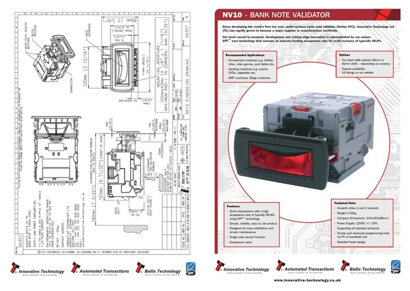
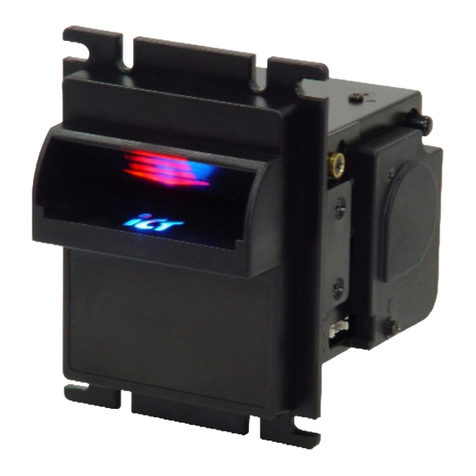
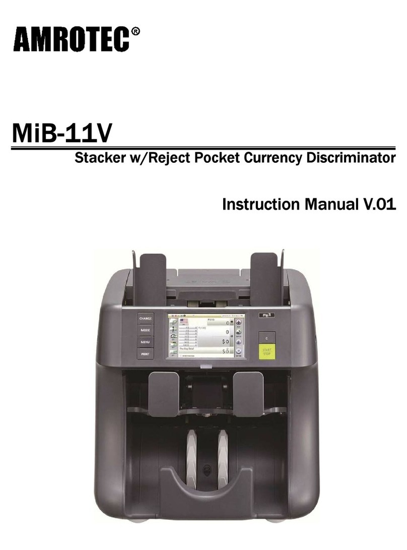
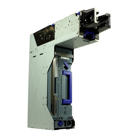
JCM GLOBAL UBA Pro Series User manual

© 2020, JAPAN CASH MACHINE CO., LTD.
Website: http://www.jcmglobal.com
UBA™ Pro Series
Universal Banknote Acceptor
Operation and Maintenance
Manual
(Revision A)
P/N 960-000211R_Rev. A
Issue #4116-SME-01-00

This product document (hereinafter referred to as “Manual”) is fully covered by legal Copyrights owned by the JAPAN
CASH MACHINE CO., LTD. (hereinafter referred to as “JCM”) under Japanese laws and foreign countries. This Manual
contains many copyrighted, patented or properly registered equipment items manufactured by JCM, that are prohibited
and illegal to duplicate, replicate, or copy in whole, or in part, without the express authorization by JCM with the following
exceptions:
1. When an authorized JCM agency or distributor duplicates the Manual for sales promotion and/or service
maintenance of the product, or technical service personnel education as required; and
2. When an end user duplicates the Manual to maintain operation of the product or operate the product in general.
JCM retains all rights to amend, alter, change or delete any portion of this Manual in whole, or in part, or add items
thereto without notice regarding the product or its related products.
JCM is a registered trademark of JAPAN CASH MACHINE CO., LTD. All other product names mentioned herein may be
registered trademarks or trademarks of their respective companies. Furthermore, ™, ® and © are not always mentioned
in each case throughout this publication.
Copyright © 2020 By JAPAN CASH MACHINE CO., LTD.
UBA™ Pro Series Universal Banknote Acceptor Operation and Maintenance Manual
Electrical Current Symbol
Direct Current: indicates Direct Current values on product labels.
International Compliance
• RoHS Directive
• UL & c-UL Marks
• CE Mark
• CB Scheme
• FCC & ISED Regulations
The JCM Website for patents is: http://www.jcm-hq.co.jp/english/patents/
REVISION HISTORY
Rev №.Date Reason for Update
A Feb. 3, 2020 Initial Release
1
2
or or or
File No. E157601
JP-21497-UL
This product must not be used in residential areas.
FCC CAUTION
Changes of modification not expressly approved by the partly responsible for compliance could void the user’s authority to
operate the equipment.
Note: This equipment has been tested and found to comply with the limits for a Class A digital device, pursuant to part 15 of the
FCC Rules.
These limits are designed to provide reasonable protection against harmful interference when the equipment is operated in a
commercial environment. This equipment generates, uses, and can radiate radio frequency energy and, if not installed and used
in accordance with the instruction manual, may cause harmful interference to radio communications.
Operation of this equipment in a residential area is likely to cause harmful interference in which case the user will be required to
correct the interference at his own expense.
Issue #4116-SME-01-00

UBA™ Pro Series
Universal Banknote Acceptor
Table of Contents
P/N 960-000211R_Rev. A © 2020, JAPAN CASH MACHINE CO., LTD.
i
Page
1 GENERAL INFORMATION .................................................................................... 1-1
Description ..................................................................................................................... 1-1
UBA Pro Unit .................................................................................................................. 1-1
Model Descriptions........................................................................................................ 1-2
Type Descriptions.......................................................................................................... 1-2
Software Descriptions ................................................................................................... 1-2
Precautions..................................................................................................................... 1-2
User Cautions ..................................................................................................................1-3
Installation Cautions..................................................................................................................... 1-3
Mounting, Dismounting & Transportation..................................................................................... 1-3
Operation Cautions ...................................................................................................................... 1-3
Preventive Maintenance................................................................................................... 1-3
Disposal Considerations .................................................................................................. 1-4
Banknote Fitness Requirements...................................................................................... 1-4
Primary Features............................................................................................................ 1-4
Component Names ........................................................................................................ 1-5
Specifications.................................................................................................................1-6
Technical Specifications .................................................................................................. 1-6
Environmental Specifications ........................................................................................... 1-7
Electrical Specifications ................................................................................................... 1-7
Structural Specifications................................................................................................... 1-7
Unit Dimensions............................................................................................................. 1-8
UBA Pro with Standard 500 Note Cash Box Outside Dimension..................................... 1-8
UBA Pro with Standard or ICB 900 Note Cash Box Outside Dimension ......................... 1-9
UBA Pro with ICB 500 Note Cash Box Outside Dimension ........................................... 1-10
Installation and Maintenance Space Requirements....................................................... 1-10
Technical Contact Information ................................................................................... 1-11
Americas ........................................................................................................................ 1-11
JCM American ........................................................................................................................... 1-11
Europe, Middle East, Africa & Russia ............................................................................ 1-11
JCM Europe GmbH.................................................................................................................... 1-11
UK & Ireland...................................................................................................................1-11
JCM Europe (UK Office) ............................................................................................................ 1-11
Asia and Oceania........................................................................................................... 1-11
JCM Gold (HK) Ltd..................................................................................................................... 1-11
JAPAN CASH MACHINE CO., LTD. (HQ)................................................................................. 1-11
2 INSTALLATION ...................................................................................................... 2-1
Installation Process ....................................................................................................... 2-1
Grounding ....................................................................................................................... 2-1
Side Installation ............................................................................................................... 2-1
Rear Installation .............................................................................................................. 2-2
Transport Stand Protector Installation (For Stacking Up (SU) Installation Type)............. 2-2
Bezel Installation .............................................................................................................. 2-2
External Harness Installation ........................................................................................... 2-3

Table of Contents
Page
P/N 960-000211R_Rev. A © 2020, JAPAN CASH MACHINE CO., LTD.
ii
UBA™ Pro Series Universal Banknote Acceptor
Cash Box Lock Installation............................................................................................... 2-3
Unlock Procedure............................................................................................................. 2-3
DIP Switch Configurations ............................................................................................ 2-4
Denomination Acceptance Settings (DIP Switches at the front) ...................................... 2-4
SW1 and SW2 Configurations ......................................................................................... 2-4
Interface Settings (Sub Board 1) ................................................................................................. 2-4
Interface and Recycler Settings (Sub Board 2) ........................................................................... 2-4
LED Light Flashing Pattern ........................................................................................... 2-5
Recommended Wire....................................................................................................... 2-6
With JCM External Harness ............................................................................................. 2-6
Not using JCM External Harness ..................................................................................... 2-6
Connector Pin Assignment .......................................................................................... 2-7
Sub Board 1: USB Connector Pin Assignment ................................................................ 2-7
Sub Board 1: Photo-Coupler Isolation Connector Pin Assignment .................................. 2-8
Sub Board 1: RS232C Connector Pin Assignment .......................................................... 2-9
Sub Board 1: TTL Connector Pin Assignment ............................................................... 2-10
Sub Board 2: USB Connector Pin Assignment .............................................................. 2-11
Sub Board 2: Photo-Coupler Isolation Connector Pin Assignment ................................ 2-12
Sub Board 2: RS232C Connector Pin Assignment ........................................................ 2-13
Sub Board 2: cc-Talk Connector Pin Assignment .......................................................... 2-14
Sub Board 2: TTL Connector Pin Assignment ............................................................... 2-15
CN5 Bezel Connector Pin Assignments......................................................................... 2-15
Preventive Maintenance .............................................................................................. 2-16
Collecting Banknotes ..................................................................................................... 2-16
Clearing a Banknote Jam............................................................................................... 2-16
Opening the Centering Mechanism................................................................................ 2-16
Cleaning Procedure ....................................................................................................... 2-17
Sensor and Roller Locations .......................................................................................... 2-18
Standard Interface Circuit Schematics ...................................................................... 2-19
Sub Board 1 Circuit Schematics 1 ................................................................................. 2-19
Sub Board 1 Circuit Schematics 2 ................................................................................. 2-20
Sub Board 2 Circuit Schematics 1 ................................................................................. 2-21
Sub Board 2 Circuit Schematics 2 ................................................................................. 2-22
CN5 Bezel Circuit Schematic ......................................................................................... 2-23
Operational Flowcharts ............................................................................................... 2-25
Initialization and Banknote Acceptance Flowchart......................................................... 2-25
Validation Flowchart....................................................................................................... 2-26
Collecting Flowchart....................................................................................................... 2-27
3 COMMUNICATIONS ............................................................................................... 3-1
Americas...................................................................................................................................... 3-1
JCM American........................................................................................................................... 3-1
Europe, Middle East, Africa & Russia .......................................................................................... 3-1
JCM Europe GmbH................................................................................................................... 3-1
UK & Ireland ................................................................................................................................ 3-1
JCM Europe (UK Office) ........................................................................................................... 3-1
Asia and Oceania ........................................................................................................................ 3-1
JCM Gold (HK) Ltd.................................................................................................................... 3-1

Table of Contents
Page
P/N 960-000211R_Rev. A © 2020, JAPAN CASH MACHINE CO., LTD.
iii
UBA™ Pro Series Universal Banknote Acceptor
Japan Cash Machine Co., LTD. (HQ) ....................................................................................... 3-1
4 DISASSEMBLY/REASSEMBLY ............................................................................ 4-1
Tool Requirements......................................................................................................... 4-1
UBA Pro and Cash Box Removal ................................................................................. 4-1
LED Light Module and Upper Bar Sensor Removal.................................................... 4-1
Box Sensor Removal ..................................................................................................... 4-2
Sub Board Removal ....................................................................................................... 4-2
Main Board Removal...................................................................................................... 4-3
Centering Motor Harness Assy. Removal.................................................................... 4-4
Entrance Motor Harness Assy. Removal ..................................................................... 4-5
Centering HP Board Removal ....................................................................................... 4-5
PB Encoder HP Board Removal ................................................................................... 4-6
PB Motor Harness Assy. Removal ............................................................................... 4-6
Stack Motor Harness Assy. Removal........................................................................... 4-7
Transport Motor Harness Assy. Removal.................................................................... 4-7
PDIC Array Removal ...................................................................................................... 4-8
Lower BAR Sensor Removal......................................................................................... 4-9
Slide Roller Removal ..................................................................................................... 4-9
5 WIRING DIAGRAMS .............................................................................................. 5-1
UBA Pro Wiring Diagram............................................................................................... 5-1
6 CALIBRATION AND TESTING .............................................................................. 6-1
Tool Requirements......................................................................................................... 6-1
Installation Procedures ................................................................................................. 6-1
Part 1 - JCM Tool Suite Installation ............................................................................................. 6-1
Part 2 - USB Drivers Installation ...................................................................................... 6-2
JCM Tool Suite Standard Edition Mode ....................................................................... 6-3
Software Download........................................................................................................ 6-3
Calibration ...................................................................................................................... 6-5
When to Calibrate ............................................................................................................ 6-5
Placing Reference Paper ................................................................................................ 6-5
Sensor Calibration............................................................................................................ 6-5
Performance Test Using a PC....................................................................................... 6-8
List of UBA Pro Performance Tests ................................................................................. 6-8
Launch Performance Test Program ................................................................................. 6-8
Banknote Acceptance Test with Cash Box ...................................................................... 6-8
Banknote Acceptance Test without Cash Box ................................................................. 6-9
Non-Validation Banknote Acceptance Test with Cash Box.............................................. 6-9
Non-Validation Banknote Acceptance Test without Cash Box......................................... 6-9
Non-Validation Banknote Reject Test with Cash Box ...................................................... 6-9
Feed Motor Speed Test (Forward)................................................................................. 6-10
Feed Motor Speed Test (Reverse)................................................................................. 6-10
Sensor Test....................................................................................................................6-11
Aging Test ...................................................................................................................... 6-11
DIP Switch Test.............................................................................................................. 6-11
Stacker Motor Operation Time Test............................................................................... 6-12

Table of Contents
Page
P/N 960-000211R_Rev. A © 2020, JAPAN CASH MACHINE CO., LTD.
iv
UBA™ Pro Series Universal Banknote Acceptor
PB Motor Operation Time Test ...................................................................................... 6-12
Centering Motor Operation Time Test............................................................................ 6-13
Stacker Motor Operation Test ........................................................................................ 6-13
Entrance Motor Speed Test (Forward)........................................................................... 6-14
Entrance Motor Speed Test (Reverse) .......................................................................... 6-14
Entrance and Feed Motors Simultaneous Speed Test (Forward).................................. 6-15
Entrance and Feed Motors Simultaneous Speed Test (Reverse).................................. 6-15
Performance Test without a PC .................................................................................. 6-16
List of the Performance Tests without a PC................................................................... 6-16
Banknote Acceptance with Cash Box ............................................................................ 6-17
Banknote Acceptance without Cash Box ....................................................................... 6-17
Non-Validation Banknote Acceptance with Cash Box.................................................... 6-18
Non-Validation Banknote Acceptance without Cash Box............................................... 6-18
Non-Validation Banknote Reject Test with Cash Box .................................................... 6-19
Feed Motor Operation Test (Forward) ........................................................................... 6-19
Feed Motor Operation Test (Reverse) ........................................................................... 6-20
Sensor Test....................................................................................................................6-20
Aging Test with Cash Box .............................................................................................. 6-21
DIP Switch Test.............................................................................................................. 6-21
Stacking Operation Test................................................................................................. 6-22
PB Motor Operation Test ............................................................................................... 6-23
Centering Motor Operation Test..................................................................................... 6-23
Stacker Motor Operation Test ........................................................................................ 6-24
Entrance Motor Operation Test (Forward) ..................................................................... 6-24
Entrance Motor Operation Test (Reverse) ..................................................................... 6-25
Entrance and Feed Motors Simultaneous Operation Test (Forward) ............................ 6-25
Entrance and Feed Motors Simultaneous Operation Test (Reverse) ............................ 6-26
7 EXPLODED VIEWS AND PARTS LISTS ............................................................... 7-1
UBA Pro Entire Unit Exploded View............................................................................. 7-1
UBA Pro Entire Unit Parts List ......................................................................................... 7-2
UBA Pro Upper Transport Guide Exploded View........................................................ 7-3
UBA Pro Upper Transport Guide Parts List ..................................................................... 7-4
UBA Pro Transport Unit Exploded View 1 ................................................................... 7-5
UBA Pro Transport Unit Parts List 1 ................................................................................ 7-6
UBA Pro Transport Unit Exploded View 2 ................................................................... 7-7
UBA Pro Transport Unit Parts List 2 ................................................................................ 7-7
UBA Pro Transport Unit Exploded View 3 ................................................................... 7-8
UBA Pro Transport Unit Parts List 3 ................................................................................ 7-8
UBA Pro Transport Unit Exploded View 4 ................................................................... 7-9
UBA Pro Transport Unit Parts List 4 ................................................................................ 7-9
UBA Pro Transport Unit Exploded View 5 ................................................................. 7-10
UBA Pro Transport Unit Parts List 5 .............................................................................. 7-11
UBA Pro Transport Unit Exploded View 6 ................................................................. 7-12
UBA Pro Transport Unit Parts List 6 .............................................................................. 7-12
UBA Pro Middle Bracket Exploded View ................................................................... 7-13
UBA Pro Middle Bracket Parts List ................................................................................ 7-14

Table of Contents
Page
P/N 960-000211R_Rev. A © 2020, JAPAN CASH MACHINE CO., LTD.
v
UBA™ Pro Series Universal Banknote Acceptor
UBA Pro Bottom Cover Exploded View ..................................................................... 7-15
UBA Pro Bottom Cover Parts List .................................................................................. 7-15
8 INDEX ................................................................................................................... 8-17
A TROUBLESHOOTING............................................................................................A-1
Introduction .................................................................................................................... A-1
Troubleshooting Overview............................................................................................A-1
Fault Table Listings .......................................................................................................A-1
Standard and ICB Error and Reject Code Conditions ................................................A-4
Standard Error Code Conditions..................................................................................................A-4
ICB Error Code Conditions ..........................................................................................................A-6
LED Flash Reject Error Code Conditions; Banknotes .................................................................A-6
LED Flash Reject Error Code Conditions; Barcode Tickets.........................................................A-8
Calibration Error...........................................................................................................A-10
Calibration Program Error Codes...............................................................................................A-10
Calibration Error Codes; Position Sensor ..................................................................................A-11
Calibration Error Codes; Validation Sensor ...............................................................................A-13
Calibration Error Codes; Barcode Sensor..................................................................................A-14
Maintenance Equipment..............................................................................................A-14
Maintenance Equipment ................................................................................................ A-14
Reference Paper Handling............................................................................................. A-14
B GLOSSARY ............................................................................................................B-1

P/N 960-000211R_Rev. A © 2020, JAPAN CASH MACHINE CO., LTD.
vii
UBA™ Pro Series
Universal Banknote Acceptor
List of Figures Page
Figure 1-1 UBA Pro Unit ..................................................................................................... 1-1
Figure 1-2 Precautionary Symbols ..................................................................................... 1-2
Figure 1-3 Unacceptable Banknotes .................................................................................. 1-4
Figure 1-4 UBA Pro Component Names ............................................................................ 1-5
Figure 1-5 UBA Pro Unit With 500 Note Cash Box Outside Dimension ............................. 1-8
Figure 1-6 UBA Pro Unit With Standard or ICB 900 Note Cash Box Outside Dimension .. 1-9
Figure 1-7 UBA Pro Unit With ICB 500 Note Cash Box Outside Dimension .................... 1-10
Figure 1-8 UBA Pro Unit Installation and Maintenance Space Requirements ................. 1-10
Figure 2-1 Grounding ......................................................................................................... 2-1
Figure 2-2 Side Installation ................................................................................................. 2-1
Figure 2-3 Rear Installation ................................................................................................ 2-2
Figure 2-4 Transport Stand Protector Installation (SU Installation Type) ........................... 2-2
Figure 2-5 Bezel Installation ............................................................................................... 2-2
Figure 2-6 External Harness Installation ............................................................................ 2-3
Figure 2-7 Key Hole Location ............................................................................................. 2-3
Figure 2-8 Key Hole Dimension & Cylinder Length ............................................................ 2-3
Figure 2-9 Key Lock Rotation Requirement ....................................................................... 2-3
Figure 2-10 Key Cap Installation .......................................................................................... 2-3
Figure 2-11 SW1 and SW2 Switches ................................................................................... 2-4
Figure 2-12 Collecting Banknotes ...................................................................................... 2-16
Figure 2-13 Clearing a Banknote Jam ................................................................................ 2-16
Figure 2-14 Opening Centering Mechanism ...................................................................... 2-16
Figure 2-15 General Cleaning Image ................................................................................. 2-17
Figure 2-16 UBA Pro Sensor and Roller Locations ............................................................ 2-18
Figure 2-17 UBA Pro Sub Board 1 Interface Circuit Schematic Diagram 1 ....................... 2-19
Figure 2-18 UBA Pro Sub Board 1 Interface Circuit Schematic Diagram 2 ....................... 2-20
Figure 2-19 UBA Pro Sub Board 2 Interface Circuit Schematic Diagram 1 ....................... 2-21
Figure 2-20 UBA Pro Sub Board 2 Interface Circuit Schematic Diagram 2 ....................... 2-22
Figure 2-21 UBA Pro CN5 Bezel Interface Circuit Schematic Diagram ............................. 2-23
Figure 2-22 UBA Pro Initialization and Banknote Acceptance Flowchart ........................... 2-25
Figure 2-23 UBA Pro Validation Flowchart ......................................................................... 2-26
Figure 2-24 UBA Pro Collecting Flowchart ......................................................................... 2-27
Figure 4-1 UBA Pro and Cash Box Removal ..................................................................... 4-1
Figure 4-2 LED Light Module and Upper Bar Sensor Removal 1 ...................................... 4-1
Figure 4-3 LED Light Module and Upper Bar Sensor Removal 2 ...................................... 4-2
Figure 4-4 LED Light Module and Upper Bar Sensor Removal 3 ...................................... 4-2
Figure 4-5 LED Light Module and Upper Bar Sensor Removal 4 ...................................... 4-2
Figure 4-6 Box Sensor Removal 1 ..................................................................................... 4-2
Figure 4-7 Box Sensor Removal 2 ..................................................................................... 4-2
Figure 4-8 Sub Board Removal 1 ....................................................................................... 4-2
Figure 4-9 Sub Board Removal 2 ....................................................................................... 4-3
Figure 4-10 Sub Board Removal 3 ....................................................................................... 4-3
Figure 4-11 Sub Board Removal 4 ....................................................................................... 4-3
Figure 4-12 Sub Board Removal 5 ....................................................................................... 4-3
Figure 4-13 Main Board Removal 1 ..................................................................................... 4-3
Figure 4-14 Main Board Removal 2 ..................................................................................... 4-3
Figure 4-15 Main Board Removal 3 ..................................................................................... 4-4
Figure 4-16 Centering Motor Harness Assy. Removal 1 ...................................................... 4-4
Figure 4-17 Centering Motor Harness Assy. Removal 2 ...................................................... 4-4
Figure 4-18 Centering Motor Harness Assy. Removal 3 ...................................................... 4-4

List of Figures
Page
P/N 960-000211R_Rev. A © 2020, JAPAN CASH MACHINE CO., LTD.
viii
UBA™ Pro Series Universal Banknote Acceptor
Figure 4-19 Centering Motor Harness Assy. Removal 4 ...................................................... 4-5
Figure 4-20 Entrance Motor Harness Assy. Removal .......................................................... 4-5
Figure 4-21 Centering HP Board Removal 1 ........................................................................ 4-5
Figure 4-22 Centering HP Board Removal 2 ........................................................................ 4-5
Figure 4-23 Centering HP Board Removal 3 ........................................................................ 4-5
Figure 4-24 PB Encoder HP Board Removal 1 .................................................................... 4-6
Figure 4-25 PB Encoder HP Board Removal 2 .................................................................... 4-6
Figure 4-26 PB Encoder HP Board Removal 3 .................................................................... 4-6
Figure 4-27 PB Motor Harness Assy. Removal 1 ................................................................. 4-6
Figure 4-28 PB Motor Harness Assy. Removal 2 ................................................................. 4-6
Figure 4-29 PB Motor Harness Assy. Removal 3 ................................................................. 4-6
Figure 4-30 Stack Motor Harness Assy. Removal 1 ............................................................ 4-7
Figure 4-31 Stack Motor Harness Assy. Removal 2 ............................................................ 4-7
Figure 4-32 Stack Motor Harness Assy. Removal 3 ............................................................ 4-7
Figure 4-33 Transport Motor Harness Assy. Removal 1 ...................................................... 4-7
Figure 4-34 Transport Motor Harness Assy. Removal 2 ...................................................... 4-7
Figure 4-35 Transport Motor Harness Assy. Removal 3 ...................................................... 4-8
Figure 4-36 Transport Motor Harness Assy. Removal 4 ...................................................... 4-8
Figure 4-37 Transport Motor Harness Assy. Removal 5 ...................................................... 4-8
Figure 4-38 PDIC Array Removal 1 ...................................................................................... 4-8
Figure 4-39 PDIC Array Removal 2 ...................................................................................... 4-8
Figure 4-40 PDIC Array Removal 3 ...................................................................................... 4-9
Figure 4-41 PDIC Array Removal 4 ...................................................................................... 4-9
Figure 4-42 Lower BAR Sensor Removal ............................................................................ 4-9
Figure 4-43 Slide Roller Removal 1 ..................................................................................... 4-9
Figure 4-44 Slide Roller Removal 2 ..................................................................................... 4-9
Figure 5-1 UBA Pro Wiring Diagram .................................................................................. 5-1
Figure 6-1 Tool and Harness Connections ......................................................................... 6-1
Figure 6-2 JCM Tool Suite Installation 1 ............................................................................ 6-1
Figure 6-3 JCM Tool Suite Installation 2 ............................................................................ 6-1
Figure 6-4 JCM Tool Suite Installation 3 ............................................................................ 6-2
Figure 6-5 JCM Tool Suite Installation 4 ............................................................................ 6-2
Figure 6-6 JCM Tool Suite Installation 5 ............................................................................ 6-2
Figure 6-7 USB Drivers Installation 1 ................................................................................. 6-2
Figure 6-8 USB Drivers Installation 2 ................................................................................. 6-2
Figure 6-9 Normal Mode Selection ..................................................................................... 6-3
Figure 6-10 Test Mode Selection ......................................................................................... 6-3
Figure 6-11 Software Download (Upgrade) 1 ....................................................................... 6-3
Figure 6-12 Software Download (Initial) 1 ............................................................................ 6-3
Figure 6-13 Software Download (Upgrade) 2 ....................................................................... 6-3
Figure 6-14 Software Download (Initial) 2 ............................................................................ 6-4
Figure 6-15 Software Download 3 ........................................................................................ 6-4
Figure 6-16 Software Download 4 ........................................................................................ 6-4
Figure 6-17 Software Download 5 ........................................................................................ 6-4
Figure 6-18 Software Download 6 ........................................................................................ 6-4
Figure 6-19 Software Download 7 ........................................................................................ 6-4
Figure 6-20 KS-101 Reference Paper .................................................................................. 6-5
Figure 6-21 Placing Reference Paper 1 ............................................................................... 6-5
Figure 6-22 Placing Reference Paper 2 ............................................................................... 6-5
Figure 6-23 Sensor Calibration 1 ......................................................................................... 6-5
Figure 6-24 Sensor Calibration 2 ......................................................................................... 6-5
Figure 6-25 Sensor Calibration 3 ......................................................................................... 6-6
List of Figures
Page
P/N 960-000211R_Rev. A © 2020, JAPAN CASH MACHINE CO., LTD.
ix
UBA™ Pro Series Universal Banknote Acceptor
Figure 6-26 Sensor Calibration 4 ......................................................................................... 6-6
Figure 6-27 Sensor Calibration 5 ......................................................................................... 6-6
Figure 6-28 Sensor Calibration 6 ......................................................................................... 6-6
Figure 6-29 Sensor Calibration 7 ......................................................................................... 6-6
Figure 6-30 Sensor Calibration 8 ......................................................................................... 6-6
Figure 6-31 Sensor Calibration 9 ......................................................................................... 6-7
Figure 6-32 Sensor Calibration 10 ....................................................................................... 6-7
Figure 6-33 Sensor Calibration 11 ....................................................................................... 6-7
Figure 6-34 Sensor Calibration 12 ....................................................................................... 6-7
Figure 6-35 Sensor Calibration 13 ....................................................................................... 6-7
Figure 6-36 Sensor Calibration 14 ....................................................................................... 6-7
Figure 6-37 Sensor Calibration 15 ....................................................................................... 6-7
Figure 6-38 Launch Performance Test Program 1 ............................................................... 6-8
Figure 6-39 Launch Performance Test Program 2 ............................................................... 6-8
Figure 6-40 Launch Performance Test Program 3 ............................................................... 6-8
Figure 6-41 Banknote Acceptance Test with Cash Box ....................................................... 6-8
Figure 6-42 Banknote Acceptance Test without Cash Box .................................................. 6-9
Figure 6-43 Non-Validation Banknote Acceptance Test with Cash Box .............................. 6-9
Figure 6-44 Non-Validation Banknote Acceptance Test without Cash Box ......................... 6-9
Figure 6-45 Non-Validation Banknote Reject Test without Cash Box .................................. 6-9
Figure 6-46 Feed Motor Speed Test (Forward) 1 ............................................................... 6-10
Figure 6-47 Feed Motor Speed Test (Forward) 2 ............................................................... 6-10
Figure 6-48 Feed Motor Speed Test (Reverse) 1 .............................................................. 6-10
Figure 6-49 Feed Motor Speed Test (Reverse) 2 .............................................................. 6-10
Figure 6-50 Sensor Test 1 .................................................................................................. 6-11
Figure 6-51 Sensor Test 2 .................................................................................................. 6-11
Figure 6-52 Aging Test ....................................................................................................... 6-11
Figure 6-53 DIP Switch Test 1 ........................................................................................... 6-11
Figure 6-54 DIP Switch Test 2 ........................................................................................... 6-11
Figure 6-55 DIP Switch Test 3 ........................................................................................... 6-12
Figure 6-56 Stacker Motor Operation Time Test 1 ............................................................. 6-12
Figure 6-57 Stacker Motor Operation Time Test 2 ............................................................. 6-12
Figure 6-58 PB Motor Operation Time Test 1 .................................................................... 6-12
Figure 6-59 PB Motor Operation Time Test 2 .................................................................... 6-12
Figure 6-60 Centering Motor Operation Time Test 1 ......................................................... 6-13
Figure 6-61 Centering Motor Operation Time Test 2 ......................................................... 6-13
Figure 6-62 Stacker Motor Operation Test 1 ...................................................................... 6-13
Figure 6-63 Stacker Motor Operation Test 2 ...................................................................... 6-13
Figure 6-64 Stacker Motor Operation Test 3 ...................................................................... 6-13
Figure 6-65 Stacker Motor Operation Test 4 ...................................................................... 6-13
Figure 6-66 Entrance Motor Speed Test (Forward) 1 ........................................................ 6-14
Figure 6-67 Entrance Motor Speed Test (Forward) 2 ........................................................ 6-14
Figure 6-68 Entrance Motor Speed Test (Reverse) 1 ........................................................ 6-14
Figure 6-69 Entrance Motor Speed Test (Reverse) 2 ........................................................ 6-14
Figure 6-70 Entrance and Feed Motors Simultaneous Speed Test (Forward) 1 ................ 6-15
Figure 6-71 Entrance and Feed Motors Simultaneous Speed Test (Forward) 2 ................ 6-15
Figure 6-72 Entrance and Feed Motors Simultaneous Speed Test (Reverse) 1 ............... 6-15
Figure 6-73 Entrance and Feed Motors Simultaneous Speed Test (Reverse) 2 ............... 6-15
Figure 6-74 Banknote Acceptance with Cash Box 1 .......................................................... 6-17
Figure 6-75 Banknote Acceptance with Cash Box 2 .......................................................... 6-17
Figure 6-76 Banknote Acceptance with Cash Box 3 .......................................................... 6-17
Figure 6-77 Banknote Acceptance without Cash Box 1 ..................................................... 6-17

List of Figures
Page
P/N 960-000211R_Rev. A © 2020, JAPAN CASH MACHINE CO., LTD.
x
UBA™ Pro Series Universal Banknote Acceptor
Figure 6-78 Banknote Acceptance without Cash Box 2 ..................................................... 6-17
Figure 6-79 Banknote Acceptance without Cash Box 3 ..................................................... 6-17
Figure 6-80 Non-Validation Banknote Acceptance with Cash Box 1 ................................. 6-18
Figure 6-81 Non-Validation Banknote Acceptance with Cash Box 2 ................................. 6-18
Figure 6-82 Non-Validation Banknote Acceptance with Cash Box 3 ................................. 6-18
Figure 6-83 Non-Validation Banknote Acceptance without Cash Box 1 ............................ 6-18
Figure 6-84 Non-Validation Banknote Acceptance without Cash Box 2 ............................ 6-18
Figure 6-85 Non-Validation Banknote Acceptance without Cash Box 3 ............................ 6-18
Figure 6-86 Non-Validation Banknote Reject Test with Cash Box 1 .................................. 6-19
Figure 6-87 Non-Validation Banknote Reject Test with Cash Box 2 .................................. 6-19
Figure 6-88 Non-Validation Banknote Reject Test with Cash Box 3 .................................. 6-19
Figure 6-89 Feed Motor Operation Test (Forward) 1 ......................................................... 6-19
Figure 6-90 Feed Motor Operation Test (Forward) 2 ......................................................... 6-19
Figure 6-91 Feed Motor Operation Test (Forward) 3 ......................................................... 6-19
Figure 6-92 Feed Motor Operation Test (Forward) 4 ......................................................... 6-19
Figure 6-93 Feed Motor Operation Test (Reverse) 1 ......................................................... 6-20
Figure 6-94 Feed Motor Operation Test (Reverse) 2 ......................................................... 6-20
Figure 6-95 Feed Motor Operation Test (Reverse) 3 ......................................................... 6-20
Figure 6-96 Feed Motor Operation Test (Reverse) 4 ......................................................... 6-20
Figure 6-97 Sensor Test 1 .................................................................................................. 6-20
Figure 6-98 Sensor Test 2 .................................................................................................. 6-20
Figure 6-99 Sensor Test 3 .................................................................................................. 6-20
Figure 6-100 Aging Test with Cash Box 1 ............................................................................ 6-21
Figure 6-101 Aging Test with Cash Box 2 ............................................................................ 6-21
Figure 6-102 Aging Test with Cash Box 3 ............................................................................ 6-21
Figure 6-103 DIP Switch Test 1 ........................................................................................... 6-21
Figure 6-104 DIP Switch Test 2 ........................................................................................... 6-22
Figure 6-105 DIP Switch Test 3 ........................................................................................... 6-22
Figure 6-106 DIP Switch Test 4 ........................................................................................... 6-22
Figure 6-107 DIP Switch Test 5 ........................................................................................... 6-22
Figure 6-108 DIP Switch Test 6 ........................................................................................... 6-22
Figure 6-109 DIP Switch Test 7 ........................................................................................... 6-22
Figure 6-110 Stacking Operation Test 1 .............................................................................. 6-22
Figure 6-111 Stacking Operation Test 2 .............................................................................. 6-22
Figure 6-112 Stacking Operation Test 3 .............................................................................. 6-22
Figure 6-113 PB Motor Operation 1 ..................................................................................... 6-23
Figure 6-114 PB Motor Operation 2 ..................................................................................... 6-23
Figure 6-115 PB Motor Operation 3 ..................................................................................... 6-23
Figure 6-116 PB Motor Operation 4 ..................................................................................... 6-23
Figure 6-117 Centering Motor Operation 1 .......................................................................... 6-23
Figure 6-118 Centering Motor Operation 2 .......................................................................... 6-23
Figure 6-119 Centering Motor Operation 3 .......................................................................... 6-23
Figure 6-120 Centering Motor Operation 4 .......................................................................... 6-23
Figure 6-121 Stacker Motor Operation Test 1 ...................................................................... 6-24
Figure 6-122 Stacker Motor Operation Test 2 ...................................................................... 6-24
Figure 6-123 Stacker Motor Operation Test 3 ...................................................................... 6-24
Figure 6-124 Stacker Motor Operation Test 4 ...................................................................... 6-24
Figure 6-125 Entrance Motor Operation Test (Forward) 1 ................................................... 6-24
Figure 6-126 Entrance Motor Operation Test (Forward) 2 ................................................... 6-24
Figure 6-127 Entrance Motor Operation Test (Forward) 3 ................................................... 6-24
Figure 6-128 Entrance Motor Operation Test (Forward) 4 ................................................... 6-24
Figure 6-129 Entrance Motor Operation Test (Reverse) 1 ................................................... 6-25

List of Figures
Page
P/N 960-000211R_Rev. A © 2020, JAPAN CASH MACHINE CO., LTD.
xi
UBA™ Pro Series Universal Banknote Acceptor
Figure 6-130 Entrance Motor Operation Test (Reverse) 2 ................................................... 6-25
Figure 6-131 Entrance Motor Operation Test (Reverse) 3 ................................................... 6-25
Figure 6-132 Entrance Motor Operation Test (Reverse) 4 ................................................... 6-25
Figure 6-133 Entrance and Feed Motors Simultaneous Speed Test (Forward) 1 ................ 6-25
Figure 6-134 Entrance and Feed Motors Simultaneous Speed Test (Forward) 2 ................ 6-25
Figure 6-135 Entrance and Feed Motors Simultaneous Speed Test (Forward) 3 ................ 6-25
Figure 6-136 Entrance and Feed Motors Simultaneous Speed Test (Forward) 4 ................ 6-25
Figure 6-137 Entrance and Feed Motors Simultaneous Speed Test (Reverse) 1 ............... 6-26
Figure 6-138 Entrance and Feed Motors Simultaneous Speed Test (Reverse) 2 ............... 6-26
Figure 6-139 Entrance and Feed Motors Simultaneous Speed Test (Reverse) 3 ............... 6-26
Figure 6-140 Entrance and Feed Motors Simultaneous Speed Test (Reverse) 4 ............... 6-26
Figure 7-1 UBA Pro Entire Unit Exploded View ................................................................. 7-1
Figure 7-2 UBA Pro Upper Transport Guide Exploded View ............................................. 7-3
Figure 7-3 UBA Pro Transport Unit Exploded View 1 ........................................................ 7-5
Figure 7-4 UBA Pro Transport Unit Exploded View 2 ........................................................ 7-7
Figure 7-5 UBA Pro Transport Unit Exploded View 3 ........................................................ 7-8
Figure 7-6 UBA Pro Transport Unit Exploded View 4 ........................................................ 7-9
Figure 7-7 UBA Pro Transport Unit Exploded View 5 ...................................................... 7-10
Figure 7-8 UBA Pro Transport Unit Exploded View 6 ...................................................... 7-12
Figure 7-9 UBA Pro Middle Bracket Exploded View ........................................................ 7-13
Figure 7-10 UBA Pro Bottom Cover Exploded View .......................................................... 7-15
Figure A-1 Calibration Error Code Pop-Up Screen ........................................................... A-10
Figure A-2 Additional Maintenance Equipment Requirements ......................................... A-14

P/N 960-000211R_Rev. A © 2020, JAPAN CASH MACHINE CO., LTD.
xiii
UBA™ Pro Series
Universal Banknote Acceptor
List of Tables Page
Table 1-1 UBA Pro Model Number Specifications ............................................................. 1-2
Table 1-2 UBA Pro Type Number Specifications ............................................................... 1-2
Table 1-3 UBA Pro Software Number Specifications......................................................... 1-2
Table 1-4 UBA Pro Technical Specification ....................................................................... 1-6
Table 1-5 UBA Pro Environmental Specifications.............................................................. 1-7
Table 1-6 UBA Pro Electrical Specification ........................................................................ 1-7
Table 1-7 UBA Pro Series Structural Specification ............................................................ 1-7
Table 2-1 Denomination Acceptance Settings ................................................................... 2-4
Table 2-2 Sub Board 1 Interface Settings .......................................................................... 2-4
Table 2-3 Sub Board 2 Interface Settings .......................................................................... 2-4
Table 2-4 LED Light Flashing Pattern ................................................................................ 2-5
Table 2-5 Sub Board 1 USB Connector Pin Assignments ................................................. 2-7
Table 2-6 Sub Board 1 Photo-Coupler Isolation Interface Pin Assignments...................... 2-8
Table 2-7 Sub Board 1 RS232C Connector Pin Assignments ........................................... 2-9
Table 2-8 Sub Board 1TTL Connector Pin Assignments ................................................. 2-10
Table 2-9 Sub Board 2 USB Connector Pin Assignments ............................................... 2-11
Table 2-10 Sub Board 2 Photo-Coupler Isolation Interface Pin Assignments.................... 2-12
Table 2-11 Sub Board 2 RS232C Connector Pin Assignments ......................................... 2-13
Table 2-12 Sub Board 2 cc-Talk Connector Pin Assignments ........................................... 2-14
Table 2-13 Sub Board 2 TTL Connector Pin Assignments ................................................ 2-15
Table 2-14 CN5 Bezel Connector Pin Assignments .......................................................... 2-15
Table 2-15 UBA Pro Sensors and Cleaning Methods........................................................ 2-18
Table 6-1 List of the UBA Pro Performance Tests ............................................................. 6-8
Table 6-2 Performance Tests without a PC and DIP Switch Settings.............................. 6-16
Table 7-1 UBA Pro Entire Unit Parts List ........................................................................... 7-2
Table 7-2 UBA Pro Upper Transport Guide Parts List ....................................................... 7-4
Table 7-3 UBA Pro Transport Unit Parts List 1 .................................................................. 7-6
Table 7-4 UBA Pro Transport Unit Parts List 2 .................................................................. 7-7
Table 7-5 UBA Pro Transport Unit Parts List 3 .................................................................. 7-8
Table 7-6 UBA Pro Transport Unit Parts List 4 .................................................................. 7-9
Table 7-7 UBA Pro Transport Unit Parts List 5 ................................................................ 7-11
Table 7-8 UBA Pro Transport Unit Parts List 6 ................................................................ 7-12
Table 7-9 UBA Pro Middle Bracket Parts List .................................................................. 7-14
Table 7-10 UBA Pro Bottom Cover Parts List .................................................................... 7-15
Table A-1 General Fault Conditions ................................................................................... A-1
Table A-2 Calibration Fault Conditions............................................................................... A-3
Table A-3 Communication Fault Conditions ....................................................................... A-3
Table A-4 Standard LED Error Codes ................................................................................ A-4
Table A-5 ICB LED Error Codes......................................................................................... A-6
Table A-6 LED Flash Reject Error Codes For Banknotes .................................................. A-6
Table A-7 LED Flash Reject Error Codes For Barcode Tickets ......................................... A-8
Table A-8 Calibration Program Error Codes..................................................................... A-10
Table A-9 Position Sensor Calibration Error Codes ......................................................... A-11
Table A-10 Validation Sensor Calibration Error Codes ...................................................... A-13
Table A-11 Barcode Sensor Calibration Error Codes......................................................... A-14
Table A-12 Additional Maintenance Equipment Parts List ................................................. A-14

UBA™ Pro Series
Universal Banknote Acceptor
Section 1
P/N 960-000211R_Rev. A © 2020, JAPAN CASH MACHINE CO., LTD.
1-1
1 GENERAL INFORMATION
This section provides a general overview of the
UBA™ Pro Series Universal Banknote Acceptor
(UBA Pro), pictured in Figure 1-1. This section is
designed to help the user navigate through this
guide with ease. It includes the following informa-
tion:
• UBA Pro Unit
• Model Descriptions
• Type Descriptions
• Software Descriptions
• Precautions
• Primary Features
• Component Names
• Specifications
• Unit Dimensions
• Technical Contact Information
In order to make operating this device and
navigating within this manual easier, the following
illustrations are used:
• Safety Instructions need to be observed in order to
protect the operators and the equipment; these are
identified with Bold text and the following
pictographs:
• Special Notes affect the use of the UBA Pro Unit;
these are identified with italic text and the
following pictograph:
• Steps require the operator to perform specific
actions; these are identified with sequential
numbers (1, 2, 3, etc.).
Description
UBA Pro Unit
Figure 1-1 UBA Pro Unit
NOTE: The Stacking Up (SU) installation is also available by using a specified SU Bezel.

P/N 960-000211R_Rev. A © 2020, JAPAN CASH MACHINE CO., LTD.
1-2
Section 1 UBA™ Pro Series Universal Banknote Acceptor General Information
Model Descriptions
Table 1-1 lists the UBA Pro Product Model
Number Descriptions.
Type Descriptions
Table 1-2 lists the UBA Pro Type Number
Descriptions.
Software Descriptions
Table 1-3 lists the Software Number Descrip-
tions.
Precautions
The Figure 1-2 symbols are defined as follows:
1. (Type 1) Do not insert a damaged or exhibited
unfit condition Banknote; it may cause a jam
inside the unit.
Table 1-1 UBA Pro Model Number Specifications
No
(1) Model Name (UBA Pro Series)
(2) Validation Sensor
5 = World Wide Type 1 (Standard)
6 = Reserved
(3) Barcode Sensor Board (Optional)
0 = Upper only (Standard)
1 = Upper and Lower
(4) Acceptor Head Unit Type
0 = Centering Type (Banknote Short Side: 62mm - 85mm)
1 = Reserved
(5) Input Section Unit (Optional)
None = Standard
(6) Stacking Type
None = Acceptor Head Unit only
SS = Security Stacker (common for SU)
(7) Cash Box Access
None = Front Access (Standard)
Table 1-2 UBA Pro Type Number Specifications
No
(1)
Cash Box Capacity
0 = No Cash Box (Acceptor Head Unit only)
5 = 500 notes (Street Grade)
9 = 900 notes (Street Grade)
(2) Cash Box Type
0 = Deep Green (Standard)
(3) Cash Box Handle
0 = Blue (Standard)
(4)
Acceptor Head Unit Sub Board Type
0 = Unassigned Number
1 = Sub Board 1 (RS232/Photo-Coupler Isolation/TTL/2 USBs)
2 = Sub Board 2 (RS232/Photo-Coupler Isolation/TTL/ccTalk/1 USB)
3 = Reserved
4 = Reserved
(5) Acceptor Head Unit Cover
0 = Black (Standard)
(6)
Bezel (Option)
0 = No Bezel
1 = Black/2 Green LEDs (Bezel 85) (Standard Installation)
2 = Reserved
8 = Reserved
9 = Reserved
A = Reserved
B = Black/2 Blue LEDs (SU Installation)
(7) ICB (Option)*
0 = Not Supported
1 = Supported
(8) Optional Conversion Circuit Board
0 = No Optional Conversion Circuit Board (Standard)
(9) Interface Setting (Factory Default)†
0 = Reserved
P = Photo-Coupler Isolation
R = RS232C
Model: UBA - * * * - (*) * * (*)
(1) (2)(3)(4) (6) (7)(5)
Type: * * * - * * - * * * * *(*)
(1)(2)(3)(4) (6)(7)(8)(9)(10)
(5)
(10)
External Harness
0 = None
1 = Standard Interface Harness 1 (No USB, UBA-1x Series Type)
2 = Standard Interface Harness 2 (1 USB, iPRO Series Type)
3 = Standard Interface Harness 3 (2 USBs, UBA Pro Series Type)
5 = Reserved
6 = Reserved
7 = Reserved
8 = Reserved
9 = Reserved
A = Reserved
5U = Reserved
6U = Reserved
7U = Reserved
8U = Reserved
*. A specific ICB Box is required.
†. Refer to “SW1 and SW2 Configurations” on page 2-4 for details.
Table 1-3 UBA Pro Software Number
Specifications
No
(A) Software Model Name
(B) Country Code (Denomination)*
*. The Country Code is indicated by three (3) Alphabetical Characters following the
JIS Standard.
(C) Interface Protocol Name
(D) Software Version
Table 1-2 UBA Pro Type Number Specifications
No
Type: * * * - * * - * * * * *(*)
(1)(2)(3)(4) (6)(7)(8)(9)(10)
(5)
NOTE: Refer to “Recommended Wire”
on page 2-6 for your original harness.
(A) (D)
Software: UBA-5**-(*) * *(*) * * * - 0 * * - V * .**
(B) (C)
Caution: User cautions should be
included in any user guides or manuals.
Caution: Careful measures were taken in
the design of this product to ensure its
quality; however, ensure that a fail-safe
design is used for the Host Machine to
assure safety.
Figure 1-2 Precautionary Symbols
Type1 Type2 Type3
NOTE: Refer to “Banknote Fitness
Requirements” on page 1-4.

P/N 960-000211R_Rev. A © 2020, JAPAN CASH MACHINE CO., LTD.
1-3
General Information UBA™ Pro Series Universal Banknote Acceptor Section 1
2. (Type 2) Do not expose the unit to water. The unit
contains several precision electronic devices that
can be damaged if water or any liquid is sprayed
or spilled into the unit.
3. (Type 3) Do not install the unit in a dusty
environment. Dust may damage the unit or
degrade its performance.
User Cautions
Careful measures were taken in the design of this
product to ensure its quality; however, the follow-
ing cautions pertain to all users and should be fol-
lowed for safe operation.
Installation Cautions
The Installation Cautions are defined as follows:
1. Do not allow the Unit to endure or operate at a
high temperature, in high humidity and/or in a
dusty environment. (Refer to “Environmental
Specifications” on page 1-7.)
2. Do not install the Unit into an area where
excessive vibration or shock is present.
3. The Unit is not designed for outside installation.
Be sure that the Host Machine contains enough
protection to avoid wet or dusty conditions when
installing in either an indoor or open-air space.
4. Avoid exposing the Unit to direct Sunlight and/or
Incandescent Lamp illumination. (Refer to
“Environmental Specifications” on page 1-7.)
5. Ensure that the Host Machine is designed for
daily operational access for maintenance and/or
clearing a Banknote Jam. (Refer to “Installation
and Maintenance Space Requirements” on
page 1-10.)
6. Do not use the Unit where it may be exposed to
airborne evaporated or sporadic chemicals and/or
oil.
7. Ensure that the Host Machine is designed consid-
ering the risk of electronic components that can
cause induced noise. The noise generated by the
components on the Host Machine may affect and
degrade the Validation performance.
Mounting, Dismounting & Transportation
Methods for mounting, dismounting and
transporting the Unit:
1. Be sure to turn the UBA Pro Unit’s Power OFF
before mounting or removing the Unit from its
permanent location. Plugging or unplugging
Connectors from their Receptacles while the
Power is ON may cause damage to the Unit.
2. When reassembling a disassembled Unit Section,
ensure that each part is properly replaced into its
correct location.
3. Be sure to carry the Unit by both hands when
transporting it. Holding the Unit by one hand
may cause personal injury if the Unit accidentally
becomes disassembled and falls apart.
4. Be careful not to use excessive outside pressure
on the Unit, or subject it to excessive vibration
during transportation.
5. Check that the Transport Section and/or the Cash
Box does not drop off the Unit when pulling it
forward after installing it.
6. Do not throw or apply strong external pressure on
the Unit. Improper handling may cause personal
injury and/or damage to the equipment.
7. Do not carry and/or transport the Unit without the
Cash Box in place. Strong external pressure on
the Unit without the Cash Box during transporta-
tion may cause the Frame to become distorted.
Operation Cautions
The Operation Cautions are defined as follows:
1. When closing the Unit, ensure all Service Door
including the Upper Guide locks securely.
2. Do not drop or apply external pressure on the
Cash Box. The Banknotes piled up inside of the
Cash Box may collapse.
3. Do not manually refill the Cash Box with the
Banknotes.
4. Do not remove the Cash Box during operation.
Preventive Maintenance
The preventive maintenance requirements are
defined as follows:
1. Be sure to turn the UBA Pro Unit’s Power OFF
before beginning a Maintenance Procedure. The
equipment produces improper operating signals
while in Maintenance Mode that may cause
personal injury.
2. To keep the UBA Pro Unit’s performance and
Banknote acceptance at optimal rates, clean and
maintain the Unit regularly. (Refer to “Cleaning
Procedure” on page 2-17 for the cleaning proce-
dures and schedule.)
3. Perform cleaning and maintenance regularly
when using the equipment in an smoky environ-
ment such as where excessive Automobile
exhaust emission or Cigarette Smoke may exist.
4. Be sure that the Guides or individual Unit
Sections are placed in the proper locations after a
maintenance procedure.
5. Do not redesign or disassemble the Unit.
Unauthorized use by inadequately trained
personnel, or use outside the original manufac-
turer’s intent voids the warranty.
6. If the Unit is exposed to water or other liquids,
use a clean, dry Micro-fiber Cloth to wipe off and
absorb excess liquids immediately. Any
remaining liquids may affect and degrade the
Sensors and Validation performance.
WARNING: Make sure Interface Harness
connections to the Host Machine are
shorter than 9.84 Feet (3 Meters) in
length. Cut off all unused portions of
the Interface Harness wiring to avoid
static electrical effects or short circuit
possibilities that could cause damage
to the Unit.
WARNING: This Unit is designed for
use with a Limited Power Source!
Design the Host Cabinet space to meet
all local related safety standards.
WARNING: Do not inject water or liquid
agents of any kind into the Unit, as this
may cause extreme damage to the Unit.

P/N 960-000211R_Rev. A © 2020, JAPAN CASH MACHINE CO., LTD.
1-4
Section 1 UBA™ Pro Series Universal Banknote Acceptor General Information
Disposal Considerations
The battery disposal requirements are defined as
follows:
1. Do not allow positive (+) and negative (-) battery
terminals to touch each other.
2. Use caution so that batteries stored or transported
together do not short circuit.
3. Follow federal, state and local regulations for
battery disposal.
Banknote Fitness Requirements
The following Banknote types may not validate
correctly, or worse, can cause a Banknote jam and/
or damage to the Unit’s Transport Path. Banknotes
exhibiting the following conditions illustrated in
Figure 1-3 should be avoided:
• Torn
• Worn
• Taped
• Excessive folds or wrinkles
• Dirty
• Wet and/or Oiled
• Adhering foreign objects
• Excessive miscuts, misaligns and/or misprints
Primary Features
This UBA Pro Series Banknote Acceptor Unit con-
tains the following primary features:
• The UBA Pro Unit is backwards compatible with
all previous UBA and iPRO Series Unit just by
replacing its Acceptor Head Unit. Upgrade of
current UBA or iPRO Series Unit to the new UBA
Pro Unit can be accomplished by just replacing the
Acceptor Head Unit.
• Processing speed is greater than the previous UBA
Series Units.
• By using high precision Sensors and the Automatic
Centering Mechanism, for 62-85mm wide
Banknotes, the UBA-5x0 Series Unit ensures high
Banknote acceptance.
• The JCM patented Anti-Pullback Mechanism
provides powerful protection against Banknote
stringing operations.
WARNING: Risk of explosion if battery
is replaced by an incorrect type.
Caution: Be careful to avoid personal
injury to your fingers when closing the
Upper Guide Section.
Figure 1-3 Unacceptable Banknotes
Damaged or Taped Banknotes
Wrinkled or Folded Banknotes
Curled, Folded or Partial Banknotes
Dirty Banknotes Wet or Oiled Banknotes
NOTE: For the UBA-RC and iPRO-RC
Series, a plug and play is a future
option.
Table of contents
Other JCM GLOBAL Bank Note Validator manuals

JCM GLOBAL
JCM GLOBAL TBV-100 FSH User manual

JCM GLOBAL
JCM GLOBAL iVIZION2 Series Quick setup guide

JCM GLOBAL
JCM GLOBAL WBA Series User manual

JCM GLOBAL
JCM GLOBAL VEGA Series User manual

JCM GLOBAL
JCM GLOBAL DBV Series Quick setup guide

JCM GLOBAL
JCM GLOBAL RDM-100 Series Quick setup guide

JCM GLOBAL
JCM GLOBAL Taiko PUB-7 User manual

JCM GLOBAL
JCM GLOBAL TBV Series Quick setup guide