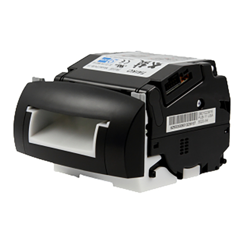
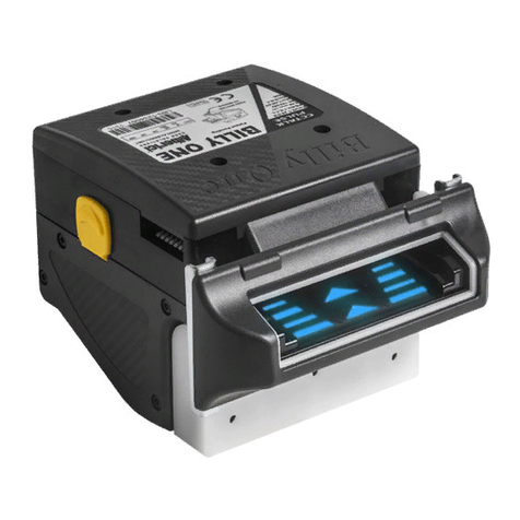
JCM GLOBAL TBV-100 FSH User manual

JCM Products
Quick Reference Guide
© 2019 JCM Global Corporation
Part No. 960-000207R_Rev. A
TBV™-100/101 Units
For more information about product set-up, use, testing procedures
and troubleshooting methods, please contact the Technical Support
Division of Customer Service via the email addresses listed below:
Americas
Europe, Middle East, Africa & Russia
Asia & Oceania
NOTE: Due to advancements in industry
technologies and future product development,
the information in this guide is subject to
change without notice.

TBV™-100/101 Units
© 2019 JCM Global Corporation 2Part No. 960-000207R_Rev. A
QUICK REFERENCE
TROUBLESHOOTING GUIDE
O
VERVIEW
This Guide applies to the following TBV Models:
Table 2 lists Issues, Probable Causes and Possible Solutions when
troubleshooting this TBV Unit.
Table 1 TBV Model Descriptions
Device Version Description
TBV-100 FSH BNF, Horizontal Stack Cash Box, Centering Path
TBV-101 FSH BNF, Horizontal Stack Cash Box, Fixed Path
TBV-100 FLD BNF, No Cash Box, Centering Path
TBV-101 FLD BNF, No Cash Box, Fixed Path
TBV-100 GLD Single note, Gated Bezel, No Cash Box, Centering Path
TBV-101 GSH Single note, Gated Bezel, Horizontal Stack Cash Box,
Fixed Path
TBV-101 ASH Single note, JCM Standard Bezel, Horizontal Stack Cash
Box, Fixed Path
Table 2 TBV Troubleshooting Descriptions
Issue Probable Cause Possible Solutions
TBV Unit is not
working. (Bezel
and CPU Board
LEDs are OFF.)
Power is not
supplied to the
TBV Unit.
Check that interface connectors are
properly fitted. Verify the Power
Supply meets specification.
The program is not
active. Firmware
Download has not
completed correctly.
Re-download the correct Firmware.
The CPU Board is
malfunctioning.
Check internal Harness and
connectors. Replace the CPU Board.
The TBV is not
communicating with
the Host machine.
Interface DIP Switch
Settings incorrect.
Check the interface settings and the
DIP Switch Settings.

© 2019 JCM Global Corporation 3Part No. 960-000207R_Rev. A
TBV™-100/101 Units
TBV Unit is
not working.
(The CPU Board’s
RED LED is lit.)
RAM Malfunction
Check TBV Harness and Connectors
are properly connected.
Replace the CPU Board.
TBV Unit is
not working.
(Fan motor cycles
ON and OFF
alternately.)
ROM Malfunction
Check TBV Harness and Connectors
are properly connected.
Replace the CPU Board.
TBV Unit is not
working. Banknote
Jam occurred.
(The TBV Bezel
LED is flashing
RED or YELLOW.)
TBV Setting
malfunction. An
improper Assembly
and/or Harness
connection exists.
A Banknote Jam or
foreign object is in
the Banknote path.
Check the TBV assembly and
connections are correct.
Check for a Banknote jam or foreign
object in the Banknote transport
path.
Check that the LED flashing pattern
is correct and identify the indicated
error by referring to the Error Codes
tables.
Most Banknotes
are rejected. (The
TBV Bezel LED is
flashing GREEN.)
The current
Firmware is not
correct for the
inserted Banknotes.
Check that the acceptable
denomination values are correct.
Download the correct Firmware.
DIP Switch Settings
are incorrect.
Check that the DIP Switch Settings
are properly set.
Banknote accept/
inhibit setting is
being made by
command from the
Host Machine.
Check that the Host commands are
correct.
Dirt or foreign
objects are adhering
to the Sensors.
Clean the Sensors.
Improper validation
process
performance.
Improper assembly
and/or Harness
connection. CPU
Board and/or Sensor
are malfunctioning.
Check that all assembly and
connections are properly set.
Identify the LED Error Code flashing
pattern and identify the error.
Refer to the Error Code Tables.
Table 2 TBV Troubleshooting Descriptions
Issue Probable Cause Possible Solutions

TBV™-100/101 Units
© 2019 JCM Global Corporation 4Part No. 960-000207R_Rev. A
DIP S
WITCH
S
ETTINGS
Figure 1 TBV DIP Switch Locations
Banknote rejects
occur and the
Banknote
Acceptance Rate
is low. (The TBV
Bezel LED is
flashing GREEN.)
The Firmware
version is old.
Banknotes require
proper denomination
from the specific
country’s Firmware
being validated.
Confirm the required denomination
and/or issued year is correct by
referring to the specific Country’s
Software Information Sheet.
Foreign objects are
adhering to the
sensors.
Clean the Sensors.
Need to perform
Sensor Calibration.
(Did not perform
Sensor Calibration
after the Unit’s
disassembly or
repair.)
Identify the LED Error flashing
pattern and locate the error (refer to
the Error Code Tables). Then
perform the necessary action
required. Perform a Validation Test.
Table 2 TBV Troubleshooting Descriptions
Issue Probable Cause Possible Solutions
NOTE: The following DIP Switches are not shown in Figure 1:
DS3 - On front of Transport
DS7 - On Cash Box
NOTE: DIP Switch DS6 Memory Selection Switch is not used.

© 2019 JCM Global Corporation 5Part No. 960-000207R_Rev. A
TBV™-100/101 Units
Table 3 DS1/DS3 - Denomination INHIBIT/ACCEPT Switches
DS1/DS3*
* Refer to the Software Information Sheet for the downloaded Firmware for DS1 or DS3 Settings.
Switch
No. Switch ON Switch OFF
1 VEND 1 INHIBIT VEND 1 ACCEPT
2 VEND 2 INHIBIT VEND 2 ACCEPT
3 VEND 3 INHIBIT VEND 3 ACCEPT
4 VEND 4 INHIBIT VEND 4 ACCEPT
5 VEND 5 INHIBIT VEND 5 ACCEPT
6 VEND 6 INHIBIT VEND 6 ACCEPT
7 VEND 7 INHIBIT VEND 7 ACCEPT
8N/A†
† N/A = Not Applicable (Never switched to ON position).
OFF (Fixed)
Table 4 DS2 - BNF Buzzer/Volume Switch
DS2
Switch
No. Switch ON Switch OFF
1 N/A OFF (Fixed)
2 Performance Buzzer ON Performance Buzzer OFF
3 ON (Fixed) N/A
4N/A*
* N/A = Not Applicable (never switched to ON position).
OFF (Fixed)
ON
OFF
ON
OFF

TBV™-100/101 Units
© 2019 JCM Global Corporation 6Part No. 960-000207R_Rev. A
DS5 (Table 6) is used in conjunction with DS4 Switches 3 and 4 (see
Table 5). All three Switches are used to set RS-232, Photo-Coupler or
cc-Talk protocol.
Table 5 DS4 - Communications Interface Settings
DS4
Switch
No. Switch ON Switch OFF
1 Fixed Type Centering Type
2Barcode Coupon (Single Read*)
* The Single Read Barcode Coupon Checksum may need to be changed for improved reading accuracy. For
higher reliability and read accuracy, the Double Read Setting is recommended for use with the TBV Validation
System.
Barcode Coupon (Double Read*)
3†
† Match each setting to equal the setting of DIP Switch DS5 Switch 1.
I/F Selection Switch #3 Switch #4
RS-232 OFF ON
4†
Photo-Coupler ON OFF
ccTalk OFF ON
ccTalk with Encryption ON ON
Table 6 DS5 - Communications Interface Setting
Switch
No. Switch ON Switch OFF
1*
* Match each setting to DIP Switch DS4 Switches 3 and 4.
Photo-Coupler RS-232
ON
OFF
ON
OFF
DS5
Photo-Coupler
RS-232

© 2019 JCM Global Corporation 7Part No. 960-000207R_Rev. A
TBV™-100/101 Units
S
TARTUP
TBV-100/101 LED C
ODES
The TBV Unit’s Front Panel Status LED indicator displays the color
patterns shown in Table 7 during initialization, downloading, normal
operation, and when error conditions occur.
Table 7 TBV LED Error Pattern Indications
Mode TBV LED
Indication TBV Condition
Normal Mode
Lit Blue Standby (waiting for a Banknote insertion).
Lit Yellow Waiting for a Host Machine Command.
OFF
(Extinguished)
BUSY (Processing validation) or an INHIBIT
Command.
Yellow
Flashes
Internal processing (Self download:
Transport section BNF Section).
Yellow
Flashes*
* Returns to Standby Mode after clearing the error condition (See Standard LED Flash Codes, Operational
Errors and Reject Codes later in this Guide to resolve the detected error type).
Banknote jam or Setting malfunction.
Red Flashes†
† Returns to Standby Mode from a RESET Command or after clearing the error condition (See Standard LED
Flash Codes, Operational Errors and Reject Codes later in this Guide to resolve the detected error type).
Abnormal (ABN) Error.
Download Mode
Green
Flashes Waiting for a Download.
Yellow
Flashes Downloading.
Green
Flashes Download completed.

TBV™-100/101 Units
© 2019 JCM Global Corporation 8Part No. 960-000207R_Rev. A
JCM T
OOL
S
UITE
The JCM Tool Suite application is used to download Firmware,
check statistics history, perform function testing and calibrate the
TBV Unit. The JCM Tool Suite is a Windows®based PC application.
O
PERATIONAL
M
ODE
/ T
EST
M
ODE
When the TBV Unit is in Operational Mode and DIP Switches DS1 or
DS3 are all OFF, the Download, Statistics and Event Log View options
are accessible from the JCM Tool Suite Service Mode Options menu
(refer to Figure 2 and Table 8).
When the TBV Unit is in Test Mode and DIP Switch DS1 or DS3
Switch #8 is ON:
• The TBV Status LED Indicator flashes White; and
•Sensor Adjustment and Performance Test options are accessible
from the Service Mode drop-down menu (Figure 2 a/ Table 8).
Figure 2 JCM Tool Suite Service Mode Drop-down Menu
NOTE: Refer to the JCM Tool Suite™Software Installation
Guide (JCM P/N 960-100923R) for further information.
a
NOTE: Refer to Table 8 JCM Tool Suite Application Functions
on page 9 for descriptions of Sensor Adjustment and
Performance Test Options.

© 2019 JCM Global Corporation 9Part No. 960-000207R_Rev. A
TBV™-100/101 Units
Table 8 JCM Tool Suite Application Functions
Mode Option/Function Purpose
Operational Mode
Download Update TBV Unit Firmware
Statistics Check Banknote/Ticket Acceptance
and any Error Status that may occur.
Event Log View Display Historical Activity on the TBV
Unit.
Test Mode
Sensor Adjustment Used to calibrate TBV Unit Sensors
Performance Test Used to test the TBV Unit’s Motor,
Solenoid and Sensor functions.

TBV™-100/101 Units
© 2019 JCM Global Corporation 10 Part No. 960-000207R_Rev. A
OPERATIONAL MODE FUNCTIONS
D
OWNLOADING
F
IRMWARE
To update the TBV Unit’s Firmware, proceed as follows:
1. Open the JCM Tool Suite Application.
2. Connect the TBV Unit to the PC using a USB Cable.
3. Click Download from the Service Mode drop-down Menu.
4. On the JCM Downloader Suite Edition Version x.xx screen (Figure
3), click the Browse button (Figure 3 a) to select the appropriate
TBV Firmware file from Windows™Explorer.
5. Click the Download button (Figure 3 b) to start the Download.
Download progress is shown by a progress barograph and a
percentage complete indication located above the Graph.
6. Verify that the download indicates Download Success. The
Download is now complete.
Figure 3 JCM Downloader Suite Edition Version x.x.x Screen
NOTE: Forced Download may be required if a new CPU
Board is installed or if the normal Download does not
complete properly.
In Forced Download Mode, DIP Switch DS1 or DS3 Switches
1, 6, 7 and 8 are ON, and Forced Download is indicated by a
Flashing GREEN LED Status Indicator.
a
b

© 2019 JCM Global Corporation 11 Part No. 960-000207R_Rev. A
TBV™-100/101 Units
BLUEWAVE DOWNLOAD TOOLS
BLUEWAVE 2.0 (DT-200)
To access BlueWave 2.0 Download Tools, perform the following
steps:
1. Copy the TBV Firmware file to the SD Card’s DOWNLOAD
folder.
2. Place the TBV Unit in Forced Download mode (with DS1 or
DS3 Switches #1, 6, 7 and 8ON).
3. Reapply Power to the TBV Unit.
4. Connect the BlueWave 2.0 (DT-200) Unit to the TBV Unit
(Figure 4 a) using a Male A to mini-B USB cable.
5. When the BlueWave 2.0 Unit’s Top LED (Figure 4 b) turns
GREEN, press the Load Button (Figure 4 d) to start the
Firmware Download.
6. When the BlueWave 2.0 Unit’s Top and Middle LEDs
(Figure 4 b/c) turn GREEN, the Download is complete.
Figure 4 BlueWave 2.0 (DT-200) Unit
b
c
a
d

TBV™-100/101 Units
© 2019 JCM Global Corporation 12 Part No. 960-000207R_Rev. A
BLUEWAVEDX (DT-300)
To access BlueWaveDX Download Tools, perform the following
steps:
1. Copy the TBV Firmware file to the TBV-100 System folder on
the SD Card for the BlueWaveDX.
2. Connect the BlueWaveDX (DT-300) Unit to the TBV Unit
using a Male A to mini-B USB Cable (Figure 5 a).
3. Slide the BlueWaveDX Power switch ON (Figure 5 b).
4. From the Firmware menu, press the OK button (Figure 5 c).
5. Scroll through the TBV Firmware versions to select the
desired version, then press the OK button (Figure 5 c).
6. Press the OK button to begin the Download (Figure 5 c).
7. When the Download is complete, press the CLR button to
return to the menu (Figure 5 d).
8. Disconnect the USB Cable from the Unit (Figure 5 a).
Figure 5 BlueWaveDX (DT-300) Unit
a
dc
b

© 2019 JCM Global Corporation 13 Part No. 960-000207R_Rev. A
TBV™-100/101 Units
PERFORMANCE TESTING
To troubleshoot the TBV100/101 Unit, either the JCM Tool Suite Appli-
cation and/or DIP Switch Settings can be used.
To access the TBV Performance Test:
1. Set TBV DIP Switch DS1 or DS3 Switch 8 to ON.
2. Apply power to the TBV Unit (the Bezel LED flashes White).
3. Connect the TBV Unit to the PC’s USB port using a Male A
to mini-B USB Cable.
4. From the JCM Tool Suite Application Service Mode drop-
down menu (refer to Figure 2), click on Performance Test.
5. Click on the TBV Performance Test to be performed. To halt
the Test, click the STOP button (Figure 6 c).
Figure 6 TBV Performance Test Options
NOTE: To use DIP Switch Settings, refer to the TBV™
Operation and Maintenance Manual (JCM P/N 960-100926R).
NOTE: When an Operation Test is selected, click the Close
box “X” icon (Figure 6 d) to halt the Test and close the screen.
c
d
ab

TBV™-100/101 Units
© 2019 JCM Global Corporation 14 Part No. 960-000207R_Rev. A
S
ENSOR
O
N
/O
FF
T
EST
To test the TBV Sensors:
1. From the TBV Performance Test Options screen (Figure 6),
click on the Sensor ON/OFF tab (Figure 6 b).
2. Click on Start to begin the Sensor Test.
3. Open the associated TBV Unit assembly to display active
Sensors or deactivated Sensors. The Sensor indication should
switch from ON to OFF or OFF to ON to indicate that the
Sensor is working properly.
4. To halt the Test, click the STOP button.
Figure 7 Opening TBV Transport Guide Rear 85 Section
NOTE: The Judgement (Validation) Sensor is not
interactive. To test it:
1) Power off the TBV Unit, then remove and rotate the Unit
Assembly 90 degrees onto its left side (Figure 7).
2) Press the twin Rear Guide Latches on the back of the
Transport Section inward (Figure 7 a) and open the Transport
Guide Rear 85 Section Validation Cover (Figure 7 b).
3) Reapply Power to the TBV Unit.
4) From the JCM Tool Suite Service Mode drop-down menu
(refer to Figure 2), click on Performance Test.
5) Click the Sensor ON/OFF tab, then click the Start button.
The Judgement Sensor Status will display as ON.
Figure 1-1
b
a
Open

© 2019 JCM Global Corporation 15 Part No. 960-000207R_Rev. A
TBV™-100/101 Units
Calibration
The TBV-100/101 Unit should be calibrated:
• after any Sensor has been replaced;
• if the CPU has been replaced; and/or
• after Preventive Maintenance has been performed.
Calibration of TBV Units is a two-step process, including:
– Calibration of Validation Sensor
– Calibration of Positioning Sensor
To calibrate the TBV Unit Validation or Positioning Sensor:
1. Click on the JCM Tool Suite Service Mode drop-down menu,
(refer to Figure 2), then click on Sensor Adjustment.
2. Click the Validation Sensor or Positioning Sensor radio button
(Figure 8 a), then click the Start button (Figure 8 b).
3. Follow the onscreen prompts to insert or remove Calibration
Reference Paper, as indicated.
Figure 8 TBV Calibration Tool [Maintenance] Screen
NOTE: To calibrate the Validation Sensor, the TBV Transport
Section must be removed from the Frame.
NOTE: To calibrate the Positioning Sensor, the TBV Transport
Section must be installed in a Frame with the Cash Box.
Figure 1-1
a
b

TBV™-100/101 Units
© 2019 JCM Global Corporation 16 Part No. 960-000207R_Rev. A
STANDARD LED FLASH CODES
Error conditions are indicated by different colors flashing on the
Bezel LED (Yellow, Red or Green). Note the number of flashes
between pauses to identify the indicated Error.
B
ANKNOTE
J
AM
E
RRORS
Banknote Jam Errors are indicated by the number of YELLOW LED
flashes. When a Sensor is blocked and the TBV Unit does not accept
a Banknote, the Bezel LED will flash Yellow. Count the flashes that
exist in between the longer pause periods to determine the correct
Error Code number (Table 9).
Table 9 Banknote Jam Error Codes
YELLOW
Flashes Error Type Cause
1 Banknote Jam
in Cash Box
When transporting Banknotes to the
Cash Box, Sensors did not detect the
correct number of Banknotes.
2Banknote Jam in
Transport Section
When transporting Banknotes in the
Transport Section, Sensors did not
detect the correct number of
Banknotes.
3 Note Chain
The BNF Assignation Sensor does not
detect an unblocked condition in the
correct timeframe.
4 Cash Box Removed The Cash Box has been removed.
5 Remaining Banknote Sensors detect a Banknote with
abnormal timing.
6 Cash Box Lock Released Sensors detect the Cash Box has been
unlocked.
7 Transport Cover Open Sensors detect that the Transport
Cover is open.
NOTE: Refer to the TBV™Series Transaction Based Validator
Operation and Maintenance Manual (JCM P/N 960-100926R)
for a full description of errors and corrective actions.

© 2019 JCM Global Corporation 17 Part No. 960-000207R_Rev. A
TBV™-100/101 Units
O
PERATIONAL
E
RRORS
Operational Errors are indicated by the number of RED LED flashes.
Note the number of flashes between pauses to identify the Error
(Table 10).
Table 10 Operational Error Codes
RED
Flashes Error Type Cause
1 Cash Box Full Detected a Cash Box Full condition.
2 Feed Motor Lockup Feed Motor encoder pulses not
detected.
3 Stacker Motor Lockup Stacker Motor encoder pulses not
detected.
4 Centering Motor Lockup Centering Motor encoder pulses not
detected.
5 BNF Unit BNF Sensors detected abnormal
movement.
6 Shutter Error Shutter Sensors detected abnormal
movement.
7Banknote Jam,
Pusher Mechanism
Pusher Mechanism home sensor is not
detected.
8Pusher Mechanism
Home Sensor
The Pusher Home Sensor is not
detected.
9 Pusher Plate Half way The Pusher Plate is not returning to the
halfway position.
10 Centering Home Sensor Centering Home Mechanism is not
returning to the home position.
11 Feed Motor Speed Motor encoder pulses out of range.
12 BNF Communications Detected communications data transfer
rate improper.
13 ICB Communications ICB Communications abnormal.
14 Voltage Input voltage is too low.
NOTE: Refer to the TBV™Series Transaction Based Validator
Operation and Maintenance Manual (JCM P/N 960-100926R)
for a full description of errors and corrective actions.

TBV™-100/101 Units
© 2019 JCM Global Corporation 18 Part No. 960-000207R_Rev. A
B
ANKNOTE
R
ETURN
/R
EJECT
E
RRORS
Banknote Reject Errors are indicated by the number of GREEN LED
flashes. Count the flashes that exist in between the longer pause
periods to determine the correct Error Code number (Table 11).
15 Banknote remaining
Sensors detected remaining Banknotes
in the Banknote path or an abnormal
timing condition.
16 I2C Access
Communications with each device on
the CPU detected an abnormal
condition.
17 Reserved N/A
18 SDRAM Reading/writing of SDRAM abnormal.
19 EEPROM Reading EEPROM reading is abnormal.
20 EEPROM Writing EEPROM writing is abnormal.
21 Feed Motor Over Current Improper current level detected while
Feed Motor is active.
22 Stacker Motor
Over Current
Improper current level detected while
Stacker Motor is active.
23 Feed Motor Overheat Sensors detected an overheat condition
while Feed Motor is active.
Table 11 Return/Reject Error Codes
GREEN
Flashes Error Type Cause and Solution
1 Skewed Insertion Detected Banknote inserted in an
incorrect direction.
2Abnormal Magnetic
detected
Magnetic Sensor detects abnormal
levels.
Table 10 Operational Error Codes (Continued)
RED
Flashes Error Type Cause
NOTE: Refer to the TBV™Series Transaction Based Validator
Operation and Maintenance Manual (JCM P/N 960-100926R)
for a full description of errors and corrective actions.

© 2019 JCM Global Corporation 19 Part No. 960-000207R_Rev. A
TBV™-100/101 Units
3Remaining Banknotes
Returned
During Initialization, Banknote was
detected in the Transport path.
4 Magnification Sensors detected an abnormal
Banknote magnification level.
5 Banknote Transport Sensors detected Banknotes in
Transport path.
6 UV Sensor UV Sensor detects abnormal Banknote
type.
7 Pattern Error Line Sensor detects an abnormal
Banknote type.
8 Double Banknotes Line Sensor detects an abnormal
Banknote type.
9 INHIBIT Setting Banknote accept/inhibit setting made
by a command from the Host.
10 Reject Command Reject command received from the
Host.
11 Cash Box Removed Sensor detected the Cash Box
Removed.
12 Banknote not recognized Sensors did not detect a valid
Banknote.
13 Banknote Length Banknote detected as longer or shorter
than specified,
14 Margin Pattern 1 Banknote pattern is greater than rated
value
15 Banknote Identity Banknote validation indicated an invalid
Banknote,
16 Margin Pattern 2 Banknote Pattern is greater than rated
value.
Table 11 Return/Reject Error Codes (Continued)
GREEN
Flashes Error Type Cause and Solution

TBV™-100/101 Units
© 2019 JCM Global Corporation 20 Part No. 960-000207R_Rev. A
C
ALIBRATION
E
RRORS
Refer to the following table if an error occurs during Calibration. To
determine which Sensor is in an Error Condition, look at the first two
(2) digits to determine when the error occurred. Then check the Vali-
dation Sensor Error Codes (Table 12) for details about the Error.
Table 12 Validation Sensor Error Codes
Sensor Calibration Digit
Number Error Code Format
Validation Sensor
[D/A Value, non-Paper] 16 digits 01-YYYY-YYYY-YYYY-YYYY*
* Refer to Table A-6 and A-7 in the TBV™ Series Transaction Based Validator Operation and Maintenance Man-
ual (JCM Part No. 960-100926R) for Sensor Flag Values indicated in the “YYYY-YYYY-YYYY-YYYY” or “zz-zz-
zz” formats.
Validation Sensor
[with the Reference Paper] 16 digits 02-YYYY-YYYY-YYYY-YYYY*
Validation Sensor
non-Paper 16 digits 05-YYYY-YYYY-YYYY-YYYY*
UV (Reflection) Sensor
with paper 8 digits 03-000-000
UV (Transmissive) Sensor
with paper 8 digits 04-000-000
UV (Transmissive) Sensor
non-paper 8 digits 06-000-000
Bar Sensor 8 digits 07-zz-zz-zz*
String Detection Sensor 8 digits 08-000-000
Positioning Sensor 8 digits 09-zz-zz-zz*
This manual suits for next models
6
Table of contents
Other JCM GLOBAL Bank Note Validator manuals
JCM GLOBAL
JCM GLOBAL Taiko PUB-7 User manual

JCM GLOBAL
JCM GLOBAL TBV Series Quick setup guide

JCM GLOBAL
JCM GLOBAL DBV Series Quick setup guide
JCM GLOBAL
JCM GLOBAL UBA Pro Series User manual

JCM GLOBAL
JCM GLOBAL VEGA Series User manual
JCM GLOBAL
JCM GLOBAL iVIZION2 Series Quick setup guide
JCM GLOBAL
JCM GLOBAL WBA Series User manual
JCM GLOBAL
JCM GLOBAL RDM-100 Series Quick setup guide