JCM GLOBAL VEGA Series User manual

© 2016, JAPAN CASH MACHINE CO., LTD.
Website: http://www.jcmglobal.com
VEGA™Series
Banknote Validator
Operation and Maintenance
Manual
(Revision 4)
P/N 960-100189R_Rev. 4 {EDP #148850}
Issue #4064-SME-01-04

This product document (hereinafter referred to as “Manual”) is fully covered by legal Copyrights owned by the JAPAN
CASH MACHINE CO., LTD. (hereinafter referred to as “JCM”) under Japanese laws and foreign countries. This Manual
contains many copyrighted, patented or properly registered equipment items manufactured by JCM, that are prohibited
and illegal to duplicate, replicate, or copy in whole, or in part, without the express authorization by JCM with the following
exceptions:
1. When an authorized JCM agency or distributor duplicates the Manual for sales promotion and/or service
maintenance of the product, or technical service personnel education as required; and
2. When an end user duplicates the Manual to maintain operation of the product or operate the product in general.
JCM retains all rights to amend, alter, change or delete any portion of this Manual in whole, or in part, or add items
thereto without notice regarding the product or its related products.
JCM is a registered trademark of JAPAN CASH MACHINE CO., LTD. All other product names mentioned herein may be
registered trademarks or trademarks of their respective companies. Furthermore, ™, ®and © are not always mentioned
in each case throughout this publication.
Copyright © 2016 By JAPAN CASH MACHINE CO., LTD.
VEGA™ Series Banknote Validator Operation and Maintenance Manual
International Compliance
• RoHS Directives
• UL & c-UL Marks
• CE Mark
• CB Scheme
• FCC Directives
Electrical Current Symbol
Direct Current: indicates Direct Current values on product labels.
REVISION HISTORY
Rev №.Date Reason for Update Comment
A 8-28-09 Initial Version
1 2-29-12 Added 24V DC Specifications, a Magnetic Sensor Specifica-
tion and MDB Information
25-1-13
Added 24V DC Specification, fixed Section 7 information
3 3-31-15
Divided Product Description into Model and Type Descrip-
tions, Added “Recycle (Option)” in Model Description,
Added VEGA-RC Twin Information to Primary Features,
Added Type FM to Outside Dimensions in Section 1/Replace
the Sensor and Roller Location graphic in Section 2/Parts
Lists Update in Section 7
4 3-28-16 Updated Bezel Information in Section 1 and 7
or or or
File No. E142330, Subscriber 8578947001, Vo.2
NO56968, NO51248/A1/M1, NO54260/M1, NO78539
FCC WARNING
Changes or modifications not expressly approved by the party responsible for compliance could void the user’s authority to
operate the equipment.
FCC NOTICE
This equipment has been tested and found to comply with the limits for a Class “A” Digital Device, pursuant to part 15 of the FCC
Rules. These limits are designed to provide reasonable protection against harmful interference when the equipment is operated
in a commercial environment.
This equipment generates, uses and can radiate radio frequency energy and, if not installed and used in accordance with the
instructions, may cause harmful interference to radio communications. Operation of this equipment in a residential area is likely
to cause harmful interference in which case the user will be required to correct the interference at his own expense.
IC NOTICE
This Class “A” Digital Apparatus complies with Canadian ICES-003.
Cet appareil numerique de la Classe “A” est conforme a la norme NMB-003 du Canada.
Issue #4064-SME-01-04

P/N 960-100189R_Rev. 4 {EDP #148850} © 2016, JAPAN CASH MACHINE CO., LTD.
i
VEGA™ Series
Banknote Validator
Table of Contents Page
1 GENERAL INFORMATION ................................................................................. 1-1
Description .................................................................................................................. 1-1
VEGA Unit ................................................................................................................... 1-1
Product Description ................................................................................................... 1-2
Model Descriptions ....................................................................................................... 1-2
Type Description ........................................................................................................... 1-2
Precautions ................................................................................................................. 1-2
User Cautions ...........................................................................................................................1-2
Installation Cautions .................................................................................................................1-2
Mounting, Dismounting and Transportation ..............................................................................1-3
Placing Foreign Objects into the Unit ....................................................................................1-3
Preventive Maintenance ...........................................................................................................1-3
Banknote Fitness Requirements .................................................................................. 1-4
Primary Features .......................................................................................................... 1-4
Component Names ..................................................................................................... 1-5
Specifications ............................................................................................................. 1-6
Technical Specifications ................................................................................................ 1-6
Environmental Specifications ....................................................................................... 1-7
Electrical Specifications ................................................................................................ 1-7
Structural Specifications ............................................................................................... 1-7
Unit Dimensions ......................................................................................................... 1-8
Entire Unit Outside Dimensions (Type SH with Standard Cash Box) ........................... 1-8
Entire Unit Clearance Dimensions (Type SH with Standard Cash Box) ...................................1-8
Entire Unit Outside Dimensions (Type SH with Large Cash Box) ................................ 1-9
Entire Unit Clearance Dimensions (Type SH with Large Cash Box) ........................................1-9
Entire Unit Outside Dimensions (Type FM with Standard Cash Box) ......................... 1-10
Entire Unit Clearance Dimensions (Type FM with Standard Cash Box) .................................1-10
Entire Unit Outside Dimensions (Type SD with Standard Cash Box) ......................... 1-11
Entire Unit Outside Dimensions (Type SD with Large Cash Box) .............................. 1-11
Entire Unit Outside Dimensions (Type SU with Standard Cash Box) ......................... 1-12
Entire Unit Outside Dimensions (Type SD with Large Cash Box) .............................. 1-12
VEGA Cash Box Outside Dimensions (Standard Cash Box) ..................................... 1-13
VEGA Cash Box Outside Dimensions (Large Cash Box) ........................................... 1-13
VEGA Cash Box Outside Dimensions (FM Cash Box) ............................................... 1-14
VEGA Bezel Outside Dimensions (Type SH) ............................................................. 1-14
VEGA Bezel Outside Dimensions (Type N) ................................................................ 1-15
VEGA Bezel Outside Dimensions (Type D) ................................................................ 1-15
Technical Contact Information ................................................................................ 1-16
Americas ................................................................................................................................1-16
JCM American .....................................................................................................................1-16
Europe, Middle East, Africa & Russia ....................................................................................1-16
JCM Europe GmbH .............................................................................................................1-16
UK & Ireland ...........................................................................................................................1-16

Table of Contents
P/N 960-100189R_Rev. 4 {EDP #148850} © 2016, JAPAN CASH MACHINE CO., LTD.
ii
Page
VEGA™ Series Banknote Validator
JCM Europe (UK Office) ...................................................................................................... 1-16
Asia and Oceania .................................................................................................................. 1-16
JCM Gold (HK) Ltd. .............................................................................................................1-16
Japan Cash Machine Co., LTD. (HQ) .................................................................................. 1-16
2 INSTALLATION ...................................................................................................2-1
Installation Procedure ................................................................................................ 2-1
SH Unit Installation ....................................................................................................... 2-1
SD/SU Unit Installation ................................................................................................. 2-1
DIP Switch Configurations ........................................................................................ 2-2
Basic Settings ............................................................................................................... 2-2
Special Settings ............................................................................................................ 2-3
LED Pattern Setting Mode .......................................................................................................2-3
Rewriting ccTalk Encryption Code (Initialize) ........................................................................... 2-3
Connector Pin Assignments .................................................................................... 2-4
Preventive Maintenance ............................................................................................ 2-4
Retrieving Banknotes ................................................................................................... 2-4
Clearing a Banknote Jam ............................................................................................. 2-5
Cleaning Procedure ................................................................................................... 2-5
Sensor and Roller Cleaning Procedure ........................................................................ 2-5
Sensor and Roller Locations ....................................................................................................2-6
Standard Interface Circuit Schematics ..................................................................... 2-7
Operation Flowchart .................................................................................................. 2-8
Operation Flowchart (Continued 1) .............................................................................. 2-9
Operation Flowchart (Continued 2) ............................................................................ 2-10
3 COMMUNICATIONS ...........................................................................................3-1
Americas .................................................................................................................................. 3-1
JCM American ....................................................................................................................... 3-1
Europe, Middle East, Africa & Russia ...................................................................................... 3-1
JCM Europe GmbH ............................................................................................................... 3-1
UK & Ireland ............................................................................................................................ 3-1
JCM Europe (UK Office) ........................................................................................................ 3-1
Asia and Oceania .................................................................................................................... 3-1
JCM Gold (HK) Ltd. ............................................................................................................... 3-1
Japan Cash Machine Co., LTD. (HQ) .................................................................................... 3-1
4 DISASSEMBLY/REASSEMBLY .........................................................................4-1
Tool Requirements ..................................................................................................... 4-1
CPU Circuit Board Removal ...................................................................................... 4-1
Upper Sensor Circuit Board Removal ...................................................................... 4-3
Sub-Circuit Board Removal ....................................................................................... 4-4
Feed and Stacker Motor Removal ................................................................................ 4-5
Sub-Sensor Circuit Board Removal ......................................................................... 4-5
Lower Sensor Circuit Board Removal ...................................................................... 4-5
Transport Belt Removal ............................................................................................. 4-6
Stacker Belt Removal ................................................................................................. 4-7
Ceiling Board Assembling Caution ............................................................................... 4-8

P/N 960-100189R_Rev. 4 {EDP #148850} © 2016, JAPAN CASH MACHINE CO., LTD.
iii
Page
VEGA™ Series Banknote Validator
Table of Contents
5 WIRING DIAGRAMS ........................................................................................... 5-1
Wiring Diagram (with Magnetic Sensor Board) ....................................................... 5-1
Wiring Diagram (without Magnetic Sensor Board) ..................................................5-2
6 CALIBRATION AND TESTING ........................................................................... 6-1
Tool Requirements ..................................................................................................... 6-1
Installation Procedures ..............................................................................................6-1
Software Download Procedure ..................................................................................... 6-2
Calibration ...................................................................................................................6-4
When to Calibrate ......................................................................................................... 6-4
Calibration Preparation ................................................................................................. 6-4
Reference Paper Usage ............................................................................................... 6-4
Calibration Using a PC ................................................................................................. 6-5
VEGA_Adjustment.exe Program Use ......................................................................................6-5
VEGA_Adjustment_Zero.exe Program Use .............................................................................6-7
Calibration Failure ...................................................................................................... 6-10
Activation Failure ....................................................................................................................6-10
USB Driver Confirmation Message ......................................................................................6-10
Communication Error Message ...........................................................................................6-10
Calibration Failure ..................................................................................................................6-10
Sensor Error Message .........................................................................................................6-10
Adjustment Data Writing Failure ............................................................................................. 6-11
Menu Item Functions .................................................................................................. 6-12
Writing Serial Number ............................................................................................................6-12
Reading a Serial Number .......................................................................................................6-13
Reading ccTalk Encryption Code ...........................................................................................6-13
Reading the ccTalk Address ...................................................................................................6-13
Writing a Standby LED Pattern Color .....................................................................................6-14
Reading a Standby LED Pattern Color ...................................................................................6-14
Reading Adjustment Data ......................................................................................................6-14
Reading the VEGA Software Version .....................................................................................6-15
Calibration without PC ................................................................................................ 6-15
Performance Tests .................................................................................................... 6-16
Performance Test Activation ....................................................................................... 6-16
DIP Switch Configuration Settings .........................................................................................6-17
Performance Test Initiation .....................................................................................................6-17
DIP Switch Test ....................................................................................................................6-17
Feed Motor Forward Rotation Test ......................................................................................6-17
Feed Motor Reverse Rotation Test ......................................................................................6-18
Stacker Motor Test ...............................................................................................................6-18
Aging Test ............................................................................................................................6-18
OFF-Line Banknote Acceptance Test ..................................................................................6-19
Reading Number of Flashes ................................................................................................6-19
Sensor Test ..........................................................................................................................6-19
7 EXPLODED VIEWS AND PARTS LISTS ........................................................... 7-1
VEGA Entire Unit View and Parts ..............................................................................7-1
VEGA Entire Exploded View (SU/SD) ....................................................................... 7-2
VEGA Entire Unit Parts List .......................................................................................... 7-3
Upper Transport Unit Entire View ............................................................................. 7-4
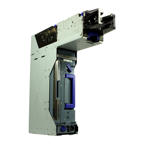
Table of Contents
P/N 960-100189R_Rev. 4 {EDP #148850} © 2016, JAPAN CASH MACHINE CO., LTD.
iv
Page
VEGA™ Series Banknote Validator
Upper Transport Unit Parts List .................................................................................... 7-5
Lower Transport Unit Exploded View ....................................................................... 7-6
Lower Transport Unit Parts List .................................................................................... 7-7
Course Path Turning Unit Exploded View ................................................................ 7-9
Course Path Turning Unit Parts List ........................................................................... 7-10
Cash Box Unit Exploded View ..................................................................................7-11
Cash Box Unit Parts Lit .............................................................................................. 7-12
SH Unit Bezel Exploded View .................................................................................. 7-14
SH Unit Bezel Parts List ............................................................................................. 7-15
SD/SU Unit Bezel Type D Exploded View ............................................................... 7-16
SD/SU Unit Bezel Type D Parts List ........................................................................... 7-17
SD/SU Unit Bezel Type N Exploded View ............................................................... 7-18
SD/SU Unit Bezel Type N Parts List ........................................................................... 7-19
SD/SU Unit Bezel Type R Exploded View ............................................................... 7-20
SD/SU Unit Bezel Type R Parts List ........................................................................... 7-21
Option Unit Exploded View ...................................................................................... 7-22
Option Unit Parts List .................................................................................................. 7-23
A TROUBLESHOOTING ........................................................................................ A-1
Introduction ................................................................................................................A-1
Troubleshooting Overview ........................................................................................A-1
Fault Table Listings ....................................................................................................A-1
Malfunction LED Error Codes .......................................................................................A-1
Error and Reject Codes .............................................................................................A-3
Error Code Table ......................................................................................................................A-3
Reject Code Table ................................................................................................................... A-5
Maintenance Equipment ............................................................................................... A-8
VEGA Maintenance Equipment ...............................................................................................A-8
B GLOSSARY ........................................................................................................ B-1

P/N 960-100189R_Rev. 4 {EDP #148850} © 2016, JAPAN CASH MACHINE CO., LTD.
v
VEGA™ Series
Banknote Validator
List of Figures Page
Figure 1-1 VEGA Unit ............................................................................................ 1-1
Figure 1-2 Precautionary Symbols ......................................................................... 1-2
Figure 1-3 Unacceptable Banknotes ...................................................................... 1-4
Figure 1-4 VEGA Component Names .................................................................... 1-5
Figure 1-5 VEGA Unit Outside Dimensions (Type SH - Standard Cash Box) ....... 1-8
Figure 1-6 VEGA Mounting Space Clearance Dimensions
(Type SH - Standard Cash Box) ........................................................... 1-8
Figure 1-7 VEGA Banknote Validator Unit Outside Dimensions
(Type SH - Large Cash Box) ................................................................ 1-9
Figure 1-8 VEGA Mounting Space Clearance (Type SH - Large Cash Box) ......... 1-9
Figure 1-9 VEGA Banknote Validator Unit Outside Dimensions
(Type FM - Standard Cash Box) ......................................................... 1-10
Figure 1-10 VEGA Mounting Space Clearance (Type FM - Standard Cash Box) . 1-10
Figure 1-11 VEGA Banknote Validator Unit Outside Dimensions
(Type SD - Standard Cash Box) ......................................................... 1-11
Figure 1-12 VEGA Banknote Validator Unit Outside Dimensions
(Type SD - Large Cash Box) .............................................................. 1-11
Figure 1-13 VEGA Banknote Validator Unit Outside Dimensions
(Type SU - Standard Cash Box) ......................................................... 1-12
Figure 1-14 VEGA Cash Box Outside Dimensions (Type SD - Large Cash Box) .. 1-12
Figure 1-15 VEGA Cash Box Outside Dimensions (Standard Cash Box) ............. 1-13
Figure 1-16 VEGA Cash Box Outside Dimensions (Large Cash Box) ................... 1-13
Figure 1-17 VEGA Cash Box Outside Dimensions (FM Cash Box) ....................... 1-14
Figure 1-18 VEGA Bezel Outside Dimensions (Type SH) ..................................... 1-14
Figure 1-19 VEGA Bezel Outside Dimensions (Type N) ........................................ 1-15
Figure 1-20 VEGA Bezel Outside Dimensions (Type D) ........................................ 1-15
Figure 2-1 M4 Nut & DIP Switch Locations............................................................ 2-1
Figure 2-2 Cable Interconnection........................................................................... 2-1
Figure 2-3 Bezel Attachment.................................................................................. 2-2
Figure 2-4 M4 Screw & Nut Removal Locations .................................................... 2-2
Figure 2-5 Cash Box & Guide Cover Location ....................................................... 2-2
Figure 2-6 DIP Switch DS1 (ccTalk Initialize) ........................................................ 2-3
Figure 2-7 Retrieving Banknotes............................................................................ 2-4
Figure 2-8 Opening the Upper Validation Section.................................................. 2-5
Figure 2-9 Retrieving Cash Box Banknote Jam ..................................................... 2-5
Figure 2-10 General Cleaning Image....................................................................... 2-5
Figure 2-11 VEGA Sensor Cleaning Locations........................................................ 2-6
Figure 2-12 VEGA Photo-Coupler/MDB Interface Schematic Diagram ................... 2-7
Figure 2-13 VEGA RS232C Interface Schematic Diagram...................................... 2-7
Figure 2-14 VEGA ccTalk Interface Schematic Diagram ......................................... 2-7
Figure 2-15 VEGA Banknote Validator Operational Flowchart (Acceptance) .......... 2-8

List of Figures
P/N 960-100189R_Rev. 4 {EDP #148850} © 2016, JAPAN CASH MACHINE CO., LTD.
vi
Page
VEGA™ Series Banknote Validator
Figure 2-16 VEGA Banknote Validator Operational Flowchart (Stacking) ............... 2-9
Figure 2-17 VEGA Banknote Validator Operational Flowchart (Reject) ................. 2-10
Figure 4-1 Cash Box & Course Path Reversing Guide Cover Removal ................. 4-1
Figure 4-2 Cash Box Frame Removal .................................................................... 4-1
Figure 4-3 Upper Assembly Separation (Part 1) .................................................... 4-2
Figure 4-4 Upper Assembly Separation (Part 2) .................................................... 4-2
Figure 4-5 Front Bezel Removal ............................................................................. 4-2
Figure 4-6 Flap Positioning Spring Removal .......................................................... 4-2
Figure 4-7 Shaft and Flap #1 & #2 Removal .......................................................... 4-2
Figure 4-8 Flap Lever Arm Reassembly ................................................................. 4-3
Figure 4-9 Upper Transport Assembly Removal .................................................... 4-3
Figure 4-10 Main CPU Board Removal .................................................................... 4-3
Figure 4-11 Upper Sensor Board Removal .............................................................. 4-3
Figure 4-12 Base Unit Carrier Removal (Part 1) ...................................................... 4-4
Figure 4-13 Base Unit Carrier Removal (Part 2) ...................................................... 4-4
Figure 4-14 Unplug Inter-Assembly Harnesses ........................................................ 4-4
Figure 4-15 Sub-Circuit Board Removal ................................................................... 4-4
Figure 4-16 Gear Box Motor Assembly Removal ..................................................... 4-5
Figure 4-17 Stacker & Feed Motor Removal ............................................................ 4-5
Figure 4-18 Sub-Sensor Board Removal ................................................................. 4-5
Figure 4-19 Lower Sensor Board Removal .............................................................. 4-6
Figure 4-20 Tension Pulley Unit Removal ................................................................ 4-6
Figure 4-21 Belt Cover Removal .............................................................................. 4-6
Figure 4-22 Transport Belt Removal ........................................................................ 4-6
Figure 4-23 Stacker Unit Removal (Part 1) .............................................................. 4-7
Figure 4-24 Stacker Unit Removal (Part 2) .............................................................. 4-7
Figure 4-25 Cash Box Turn Course Removal .......................................................... 4-7
Figure 4-26 E-Ring, Gear & Clutch Shaft Removal .................................................. 4-7
Figure 4-27 Right Stacker Belt Removal .................................................................. 4-8
Figure 4-28 Left Stacker Belt Removal ..................................................................... 4-8
Figure 4-29 Transport Belt Installation 1 .................................................................. 4-8
Figure 4-30 Transport Belt Installation 2 .................................................................. 4-8
Figure 5-1 Wiring Diagram (with Magnetic Sensor Board) ..................................... 5-1
Figure 5-2 Wiring Diagram (with Magnetic Sensor Board) ..................................... 5-2
Figure 6-1 Tool and Harness Connection ............................................................... 6-1
Figure 6-2 Tool and Harness Connection ............................................................... 6-1
Figure 6-3 Hardware Wizard Welcome Screen ...................................................... 6-1
Figure 6-4 Installation Path Selection Screen ........................................................ 6-2
Figure 6-5 Install Option Screen ............................................................................. 6-2
Figure 6-6 Installation Warning Screen .................................................................. 6-2
Figure 6-7 Hardware Wizard Completion Screen ................................................... 6-2
Figure 6-8 DIP Switch DS1 Initial Setting ............................................................... 6-2
Figure 6-9 UBA Download Screen ......................................................................... 6-3

P/N 960-100189R_Rev. 4 {EDP #148850} © 2016, JAPAN CASH MACHINE CO., LTD.
vii
Page
VEGA™ Series Banknote Validator
List of Figures
Figure 6-10 Software Selection Screen ................................................................... 6-3
Figure 6-11 Download Progress Screen ................................................................... 6-3
Figure 6-12 Software Selection Screen ................................................................... 6-3
Figure 6-13 Tool and Harness Connection .............................................................. 6-4
Figure 6-14 Reference Paper Types ........................................................................ 6-4
Figure 6-15 Upper Transport Unit Open .................................................................. 6-4
Figure 6-16 Placing Reference Paper ...................................................................... 6-5
Figure 6-17 Placing Reference Paper ...................................................................... 6-5
Figure 6-18 DIP Switch Block DS1 Initial Settings ................................................... 6-5
Figure 6-19 VEGA Adjustment Screen .................................................................... 6-5
Figure 6-20 Entrance Sensor Adjustment Screen .................................................... 6-5
Figure 6-21 White Reference paper Placement Request Dialog ............................. 6-6
Figure 6-22 White Reference Paper Calibration Progress Screen .......................... 6-6
Figure 6-23 Black Reference paper Placement Request Dialog .............................. 6-6
Figure 6-24 Black Reference paper Removal Request Dialog ................................ 6-6
Figure 6-25 Calibration without Reference Paper 1 ................................................. 6-6
Figure 6-26 Calibration without Reference Paper 2 ................................................. 6-6
Figure 6-27 Motor Speed Test ................................................................................. 6-6
Figure 6-28 White Reference paper Placement Request Dialog ............................. 6-6
Figure 6-29 White Reference paper Removal Request Dialog ................................ 6-6
Figure 6-30 Request Writing Data to EEPROM ....................................................... 6-7
Figure 6-31 Writing EEPROM Data Progress .......................................................... 6-7
Figure 6-32 Save As Screen .................................................................................... 6-7
Figure 6-33 VEGA Adjustment Complete Screen .................................................... 6-7
Figure 6-34 DIP Switch Block DS1 Initial Settings ................................................... 6-7
Figure 6-35 VEGA Adjustment Screen .................................................................... 6-7
Figure 6-36 Serial No. Input Field Location .............................................................. 6-7
Figure 6-37 LED Idle Pattern Menu Location ........................................................... 6-8
Figure 6-38 Entrance Sensor Calibration ................................................................. 6-8
Figure 6-39 White Reference paper Placement Request Dialog ............................. 6-8
Figure 6-40 White Reference Paper Calibration Progress Screen .......................... 6-8
Figure 6-41 Black Reference Paper Placement Request Dialog Screen ................. 6-8
Figure 6-42 Black Reference Paper Calibration Progress Screen ........................... 6-8
Figure 6-43 Black Reference Paper Removal Request Dialog ................................ 6-9
Figure 6-44 Calibration without Reference Paper 1 ................................................. 6-9
Figure 6-45 Calibration without Reference Paper 2 ................................................. 6-9
Figure 6-46 Motor Speed Test ................................................................................. 6-9
Figure 6-47 White Reference paper Placement Request Dialog ............................. 6-9
Figure 6-48 White Reference paper Removal Request Dialog ................................ 6-9
Figure 6-49 Request Writing Data to EEPROM ....................................................... 6-9
Figure 6-50 Clearing EEPROM Data ....................................................................... 6-9
Figure 6-51 Clearing EEPROM Data ....................................................................... 6-9
Figure 6-52 Save As Screen .................................................................................. 6-10

List of Figures
P/N 960-100189R_Rev. 4 {EDP #148850} © 2016, JAPAN CASH MACHINE CO., LTD.
viii
Page
VEGA™ Series Banknote Validator
Figure 6-53 VEGA Adjustment Complete Screen .................................................. 6-10
Figure 6-54 USB Driver Confirmation Screen ........................................................ 6-10
Figure 6-55 Communication Error Screen .............................................................. 6-10
Figure 6-56 Entrance Sensor Calibration Error ...................................................... 6-10
Figure 6-57 Retrying Calibration Message ............................................................. 6-10
Figure 6-58 Calibration Failed Message ................................................................. 6-10
Figure 6-59 Save As Screen .................................................................................. 6-11
Figure 6-60 Overwrite Confirmation ....................................................................... 6-11
Figure 6-61 Failed Data Save Error ........................................................................ 6-11
Figure 6-62 Writing Error Screen ............................................................................ 6-11
Figure 6-63 Retrying Writing Message ................................................................... 6-11
Figure 6-64 Writing Failed Message ....................................................................... 6-11
Figure 6-65 Save As Screen .................................................................................. 6-11
Figure 6-66 Overwrite Confirmation ....................................................................... 6-12
Figure 6-67 Failed Data Save Error ........................................................................ 6-12
Figure 6-68 Tool Bar Menu 1 .................................................................................. 6-12
Figure 6-69 Serial No. Window Request ................................................................ 6-12
Figure 6-70 SERIAL NO Input ................................................................................ 6-12
Figure 6-71 Writing Serial No.Complete ................................................................. 6-13
Figure 6-72 Tool Bar Menu 2 .................................................................................. 6-13
Figure 6-73 Serial No. Read Completion ................................................................ 6-13
Figure 6-74 Tool Bar Menu 3 .................................................................................. 6-13
Figure 6-75 Encryption Code Read Completion ..................................................... 6-13
Figure 6-76 Tool Bar Menu 4 .................................................................................. 6-13
Figure 6-77 Address Read Completion .................................................................. 6-13
Figure 6-78 Tool Bar Menu 5 .................................................................................. 6-14
Figure 6-79 Select LED Color ................................................................................. 6-14
Figure 6-80 Writing LED Standby Indication .......................................................... 6-14
Figure 6-81 Tool Bar Menu 6 .................................................................................. 6-14
Figure 6-82 Reading LED Standby Indication ........................................................ 6-14
Figure 6-83 Tool Bar Menu 7 .................................................................................. 6-14
Figure 6-84 Save As Screen .................................................................................. 6-14
Figure 6-85 Tool Bar Menu 8 .................................................................................. 6-15
Figure 6-86 Software Version Indication ................................................................ 6-15
Figure 6-87 Tool and Harness Connection ............................................................. 6-15
Figure 6-88 DIP Switch Settings ............................................................................. 6-15
Figure 6-89 Tool and Harness Connection ............................................................. 6-16
Figure 7-1 VEGA Entire Unit Exploded View .......................................................... 7-1
Figure 7-2 VEGA Entire Unit Exploded View (SU/SD) ........................................... 7-2
Figure 7-3 Upper Transport Unit Exploded View .................................................... 7-4
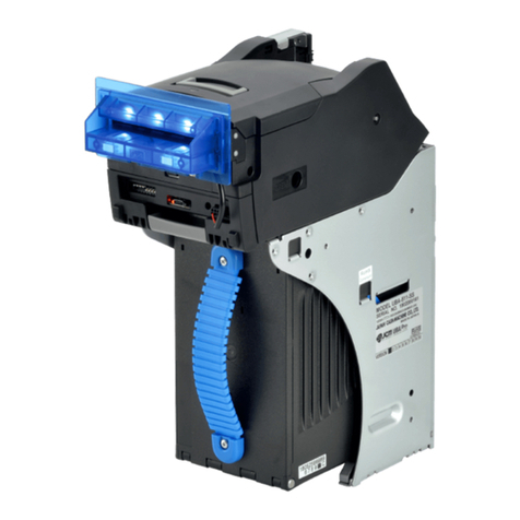
Figure 7-4 Lower Transport Unit Exploded View .................................................... 7-6
Figure 7-5 Course Turning Unit Exploded View ..................................................... 7-9
Figure 7-6 Cash Box Unit Exploded View ............................................................ 7-11

List of Figures
P/N 960-100189R_Rev. 4 {EDP #148850} © 2016, JAPAN CASH MACHINE CO., LTD.
ix
Page
VEGA™ Series Banknote Validator
Figure 7-7 SH Unit Bezel Exploded View ............................................................. 7-14
Figure 7-8 SD/SU Unit Bezel Type D Exploded View .......................................... 7-16
Figure 7-9 SD/SU Unit Bezel Type N Exploded View .......................................... 7-18
Figure 7-10 SD/SU Unit Bezel Type R Exploded View .......................................... 7-20
Figure 7-11 Option Unit Exploded View ................................................................. 7-22
Figure A-1 Additional Maintenance Equipment Requirements ...............................A-8

P/N 960-100189R_Rev. 4 {EDP #148850} © 2016, JAPAN CASH MACHINE CO., LTD.
xi
VEGA™ Series
Banknote Validator
List of Tables Page
Table 1-1 VEGA Model Number Specifications .................................................... 1-2
Table 1-2 Model Number Specifications ............................................................... 1-2
Table 1-3 VEGA Technical Specifications ............................................................ 1-6
Table 1-4 VEGA Environmental Specifications ..................................................... 1-7
Table 1-5 VEGA Electrical Specifications ............................................................. 1-7
Table 1-6 VEGA Structural Specifications ............................................................ 1-7
Table 2-1 DIP Switch Block 1 Settings ................................................................. 2-2
Table 2-3 DIP Switch Block 3 Settings ................................................................. 2-3
Table 2-4 DIP Switch DS1 Color Settings ............................................................. 2-3
Table 2-2 DIP Switch Block 2 Settings ................................................................. 2-3
Table 2-5 VEGA Pin Assignments ........................................................................ 2-4
Table 2-6 VEGA Sensor Cleaning Methods ......................................................... 2-6
Table 6-1 Red LED Flash Rate Errors ................................................................ 6-16
Table 6-2 Performance Test DIP Switch Configuration Settings ........................ 6-17
Table 6-3 Feed Motor Abnormal Error Codes ..................................................... 6-18
Table 6-4 Stacker Motor Abnormal Error Codes ................................................. 6-18
Table 6-5 Feeding/Stacking Abnormal Error Codes ........................................... 6-18
Table 6-6 Performance Test DIP Switch Configuration Settings ........................ 6-19
Table 7-1 VEGA Entire Unit Parts List .................................................................. 7-3
Table 7-2 Upper Transport Unit Parts List ............................................................ 7-5
Table 7-3 Lower Transport Unit Parts List ............................................................ 7-7
Table 7-4 Course Path Turning Parts List ........................................................... 7-10
Table 7-5 Cash Box Unit Parts List ..................................................................... 7-12
Table 7-6 SH Unit Bezel Parts List ..................................................................... 7-15
Table 7-7 VEGA SD/SU Unit Bezel Type D Parts List ........................................ 7-17
Table 7-8 VEGA SD/SU Unit Bezel Type N Parts List ........................................ 7-19
Table 7-9 VEGA SD/SU Unit Bezel Type R Parts List ........................................ 7-21
Table 7-10 Option Unit Parts List .......................................................................... 7-23
Table A-1 Fault Table Listings ............................................................................... A-1
Table A-2 Error Codes .......................................................................................... A-3
Table A-3 Reject Codes ........................................................................................ A-5
Table A-4 Additional Maintenance Equipment Parts Lists .................................... A-9

P/N 960-100189R_Rev. 4 {EDP #148850} © 2016, JAPAN CASH MACHINE CO., LTD.
1-1
VEGA™ Series
Banknote Validator
Section 1
1 GENERAL INFORMATION
This section provides a general overview of the
VEGA Series Banknote Validator Unit, pictured in
Figure 1-1. This section is designed to helpthe user
navigate through this guide with ease. It contains
the following information:
• VEGA Unit
• Product Description
• Precautions
• Primary Features
• Component Names
• Specifications
• Unit Dimensions
• Technical Contact Information
In order to make operation this device and navigat-
ing within this manual easier, the following illus-
trations are used:
Safety Instructions need to be observed in order to
protect the operators and the equipment; these are
identified with Bold text and the following picto-
graphs:
Special Notes affect the use of the Banknote Vali-
dator; these are identified with italic text and the
following pictograph:
Steps require the operator to perform specific
actions; these are identified with sequential num-
bers (1, 2, 3 etc.)
.
Description
Figure 1-1 VEGA Unit
VEGA Unit
Figure 1-1 VEGA Unit

P/N 960-100189R_Rev. 4 {EDP #148850} © 2016, JAPAN CASH MACHINE CO., LTD.
1-2
Section 1 VEGA™ Series Banknote Validator General Information
Product Description
Model Descriptions
Table 1-1 lists the product model number descrip-
tions.
Type Description
Table 1-2 lists the product type number descrip-
tions.
Precautions
Symbols in Figure 1-2 are defined as follows:
1. (Type 1) Do not insert a torn, folded, or wet
Banknote; it may cause a jam inside the unit.
2. (Type 2) Do not expose the unit to water. The unit
contains several precision electronic devices that
can be damaged if water or any liquid is sprayed
or spilled into the unit.
3. (Type 3) Do not install the unit in a dusty envi-
ronment. Dust may affect/degrade the sensor’s
performance.
User Cautions
Careful measures were taken in the design of this
product to ensure its quality; however, the follow-
ing cautions pertain to all users and should be fol-
lowed for safe operation.
Installation Cautions
The installation Cautions are defined as follows:
1. This unit is not designed for outdoor installation.
Be sure the Host Machine contains enough pro-
tection to avoid wet or dusty conditions when
installing it in both open-air and indoor spaces.
Table 1-1 VEGA Model Number Specifications
NoModel: VEGA - * * * - *** - ****
No(1) (2,3,4) (5) (6)
(1) Product Series Name
(2) CPU Board Type
1 = Standard
(3) Durability
0 = Standard
(4) SUB Board
0 = 12V DC Power (NO Magnetic Sensor)
1 = 12V DC Power / Magnetic Sensor (W)
2 = 24V DC Power / NO Magnetic Sensor
3 = 24V DC Power / Magnetic Sensor (J)
4 = 24V DC Power / Magnetic Sensor (W)
5 = 12V DC Power / Magnetic Sensor (J)
(5) Stacker Type
SH = Downward horizontal stacking
SU = Upward vertical stacking
SD = Downward vertical stacking.
(6) Recycle (Option)*
None = No Recycler
RC1 = Recycler Featured (1 Drum)
RC20 = Recycler Featured (2 Drums/Standard)
RC21 = Recycler Featured (2 Drums/Vehicle Specification)
*. Optional recycler units details are explained in each Operation and
Maintenance Manual. Refer to VEGA-RC Operation and Maintenance
Manual for using the RC1 or the VEGA-RC Twin Operation and Main-
tenance Manual for using the RC20/RC21.
Table 1-2 Model Number Specifications
NoModel: **** - * * ** * - ** - **
No(1) (2,3,4,5) (6) (7)
(1) Country Code
Refer to the “Software Information Sheet”
(2) Cash Box
3 = Standard Box
A = Large Box
(3) Lock
0 =Thumb Lock
(4) Bezel
01 = SH 68mm (EUR)
02 = SH 76mm (GBR/SCO/NIRL)
03 = SH 71mm (RUS)
04 = SH 77mm (JPN)
05 = SH 67mm (USA)
11 = SH 68mm (EUR) + Metal Bezel (EUR)
21 = SH 71mm Long Bezel (TYPE 3)
22 = SH 71mm Long Bezel (TYPE 4)
N1 = SU/SD 68mm (EUR)
N2 = SU/SD 76mm (GBR/SCO/NIRL)
D1 = SU/SD 67mm (USA)
D2 = SU/SD 71mm (RUS)
D3 = SU/SD 68mm (EUR)
R1 = SU/SD 71mm (RUS)
(5) Box Access
F = Front Access
B = Rear Access
(6) Option
00 = NO Option
01 = Frame Key
02 = Bezel Protector
03 = Frame Key + Bezel Protector
(7) Interface
I4 = 4 Types
Table 1-2 Model Number Specifications
NoModel: **** - * * ** * - ** - **
No(1) (2,3,4,5) (6) (7)
Figure 1-2 Precautionary Symbols
Type 1 Type 2 Type 3
Figure 1-2 Precautionary Symbols

P/N 960-100189R_Rev. 4 {EDP #148850} © 2016, JAPAN CASH MACHINE CO., LTD.
1-3
General Information VEGA™ Series Banknote Validator Section 1
2. Be sure the Host Machine is designed with care-
ful consideration for retrieving a Banknote and/or
cleaning a Banknote jam.
3. Be careful not to use excessive outside pressure
on the Unit Frame when removing the Cash Box
from the Unit.
4. Avoid exposing the Banknote Insertion Slot to
direct Sunlight and/or Incandescent Lamp illumi-
nation having a Gradient Angle of 15 Degrees or
more, and an illumination index of 3000 Lux or
less. Insure that the Host Machine is also
designed to avoid exposing the Banknote Inser-
tion Slot to direct Sunlight or incandescent light.
5. Do not allow the Validator to endure a range of
temperature and humidity beyond the environ-
mental limits specified (See “Environmental
Specifications” on page 1-7).
6. Do not use the Validator in environments that
may be subject to extreme temperature changes.
7. Do not use the Validator where it may be exposed
to airborne evaporated or sporadic chemicals.
8. Clean and maintain the Validator regularly when
located in an excessively smoke filled environ-
ment.
9. When installing the equipment, connect the
Frame Housing to the Frame Ground of the Host
Machine.
10. Because this equipment is a component product,
close the Host Machine’s door before using it.
11. Do not operated the Unit while the Cash Box
Door is open. Personal injury may occur.
Mounting, Dismounting and Transporta-
tion
Methods for mounting, dismounting, and transport-
ing the unit:
1. Be sure to turn the Unit’s power OFF before
mounting or removing the optional or sub unit(s).
2. Plugging or unplugging the communications con-
nector while the Unit’s power is ON may cause
damage to the other unit(s).
3. Be sure to carry the Unit using both hands. Hold-
ing the Unit with only one hand may cause per-
sonal injury if the unit comes apart.
4. While transporting, be careful not to apply too
much pressure to the unit, or subject it to excess
vibration.
5. Do not throw or apply excessive force to the unit.
P
LACING
F
OREIGN
O
BJECTS
INTO
THE
U
NIT
Observe the following precautions when placing
foreign objects into the Unit:
1. Do not insert anything except Banknotes into the
Insertion Slot. Inserting Receipts, Staples Tick-
ets, Rubber Bands, or Credit Card into the Unit
may damage the Banknote Transport path.
2. Do not inject liquids into the Banknote Insertion
Slot. Injecting water, oil or cleaning agents may
damage the Sensors within the Banknote Trans-
port path.
Preventive Maintenance
The preventive maintenance requirements are
defined as follows:
1. Be sure to turn the Power OFF before beginning
a maintenance procedure. The equipment pro-
duces improper operating signals while in main-
tenance mode that may cause personal injury.
2. When closing the section(s) having latches or
tabs, ensure that it clicks firmly into place.
3. When reassembling a disassembled unit, ensure
that each part is carefully placed in its proper
location.
4. Be sure that the Guides and Unit sections are
placed in the proper location after a maintenance
procedure.
5. Use a soft, lint-free cloth, cotton swab or com-
pressed air spray to clean dust and debris from
the Banknote path and the inside areas of the
Unit.
6. Perform routine cleaning and maintenance at
least once a month to keep the Validation Unit’s
performance stable.
7. If the Unit is exposed to water or other liquids,
use a clean, dry micro-fiber cloth to wipe off and
absorb excess liquids immediately. Any remain-
ing liquids may affect and degrade the Sensors
and Validation performance.
8. Do not redesign or disassemble the Unit. Unau-
thorized use by inadequately trained personnel,
or use outside the original manufacturer’s intent
for operation voids the warranty.
9. If unused Interface Harness exists, cut the Har-
ness off short to avoid attracting static electricity
or a short circuit possibility that may cause dam-
age to the Unit.
Caution: Turn the Unit’s power
supply OFF before opening the
Upper or Lower Guide;
otherwise, the rollers could
begin operating and cause injury
by pulling fingers into the unit.
Caution: Be careful to avoid any
personal injury to fingers when
closing the Guide Section.
WARNING: Use only non-
flammable compressed air when
necessary to clean dust by using
a compressed air spray.
WARNING: Do not inject water or
liquid agents of any kind into the
Unit; as this may cause extreme
damage to the Unit.
Caution: Do not use any alcohol,
thinner, or citrus-based products
for cleaning any surfaces or
sensors that can damage the
plastic surface when cleaning it.

P/N 960-100189R_Rev. 4 {EDP #148850} © 2016, JAPAN CASH MACHINE CO., LTD.
1-4
Section 1 VEGA™ Series Banknote Validator General Information
Banknote Fitness Requirements
The following Banknote types may not validate
correctly, or can cause a Banknote jam and/or dam-
age to the Unit’s Transport Path. Banknotes exhib-
iting the conditions listed below and illustrated in
Figure 1-3 should be avoided:
• Torn
• Having excessive folds
• Having excessive wrinkles
• Dirty
• Wet
• Adhering foreign objects and/or oil
Primary Features
The VEGA contains the following primary fea-
tures:
• The ability to replace an identical VEGA Unit
installation (e.g., a Unit having and SH
specification or a SD/SU specification) into a wide
range of target Host Machines by changing the
Bezel and the Cash Box stop location.
• A single denomination can flow in reverse by
adding the VEGA-RC.
• Any two (2) denominations can be recycled by
adding the VEGA-RC Twin Unit.
Caution: Make sure Interface
Harness connections to the Host
Machine are shorter than 3
Meters (9.84 Feet) in length. Cut
off all unused portions of the
Interface Harness wiring.
Figure 1-3 Unacceptable Banknotes
Damaged Banknotes
Wrinkled Banknotes
Curled Banknotes
Folded or Partial Banknotes
Figure 1-3 Unacceptable Banknotes

P/N 960-100189R_Rev. 4 {EDP #148850} © 2016, JAPAN CASH MACHINE CO., LTD.
1-5
General Information VEGA™ Series Banknote Validator Section 1
Component Names
Figure 1-4 illustrates the VEGA Component Names and locations.
Figure 1-4 VEGA Component Names
e
a) Upper Section
b) Bezel
c) Upper Section Open/Close Buttons
d) Cash Box
e) USB Connector Receptacle Cover
f) Interface Connector Receptacle
g) Recycler (RC) Connector Receptacle
h) DIP Switches
i) Course Path Reversing Guide
j) Course Path Reversing Guide Cover Release
Buttons
k) Cash Box Door
l) Thumb Lock Knob
m) Banknote Insertion Slot
n) Frame Lock (Option)
a
b
c
d
gf
h
j
l
k
i
m
n

P/N 960-100189R_Rev. 4 {EDP #148850} © 2016, JAPAN CASH MACHINE CO., LTD.
1-6
Section 1 VEGA™ Series Banknote Validator General Information
Specifications
Technical Specifications
Table 1-3 VEGA Technical Specifications
Accepted Denominations: Refer to the Specific Country’s “Software Information Sheet”
Acceptance Rate:*
*. Based on new Euro Banknotes. Refer to the “Software Information Sheet” for each Country’s Banknote particular acceptance rate.
95% or greater
The following Banknote types are excluded:
•Banknotes with excess or poor magnetism or unclear graphics.
•Double (dual) Banknotes.
•Worn, dirty, wet, stained, torn or excessively wrinkled Banknotes.
•Banknotes having folded corners or edges.
•Banknotes having the wrong cut dimensions or printing displacement.
•Returned Banknote because of incorrect or failed insertion.
•Banknotes having excessive or insufficient Magnetic-ink (when Magnetic Sen-
sor contact occurs)
Banknote Types Accepted: Long side: 110-165mm (4.33-6.5 in.)
Short side: 60-82mm (2.36-3.23 in.)
Insertion Direction: Four (4) ways
Validation Method: Optical, 5 wavelength (transparency and reflection)
Processing Speed:†
†. Based on Euro Banknote sizes. Processing time depends on the Host communication time lag.
•Approximately 2 seconds (from Banknote insertion to vend signal output)
•Approximately 3 seconds (from Banknote insertion to completion of stacking)
•Approximately 3 seconds (from Banknote insertion to enable of next insertion)
Diagnostic Indicators: LED (full-Color range)
Escrow: 1 Banknote
Sequential Operation: Not supported (Sequential Operation by more than 100 Banknotes is
prohibited).
Anti-stringing Mechanism: Optical and mechanical combination.
Cash Box Capacity: Approximately 300 notes (new Banknotes for Standard Cash Box)
Approximately 1000 notes (new Banknotes for Large Cash Box)
Cash Box Access: Front or Rear (SH Type)
Upward (SU or SD Type)
Cash Box Type: Standard Cash Box
Large Cash Box.
Interface:‡
‡. Related Parameters for the respective Interface type or types listed.
a) Photo-coupler Isolation
b) RS232C
c) ccTalk
d) † (a~b) = ID-003
e) †(c) = ID-0E3
Table of contents
Other JCM GLOBAL Bank Note Validator manuals

JCM GLOBAL
JCM GLOBAL TBV-100 FSH User manual

JCM GLOBAL
JCM GLOBAL DBV Series Quick setup guide

JCM GLOBAL
JCM GLOBAL WBA Series User manual

JCM GLOBAL
JCM GLOBAL TBV Series Quick setup guide

JCM GLOBAL
JCM GLOBAL Taiko PUB-7 User manual

JCM GLOBAL
JCM GLOBAL iVIZION2 Series Quick setup guide

JCM GLOBAL
JCM GLOBAL RDM-100 Series Quick setup guide

JCM GLOBAL
JCM GLOBAL UBA Pro Series User manual