JCM GLOBAL TBV Series Quick setup guide

© 2010, Japan CashMachine Co, Limited
Support: http://www.jcmglobal.com/en/contact/default.aspx Web-Site: http://www.jcmglobal.com
Issue #4060-IGE-01-00
TBV™Series
Transaction Based Validator
Integration Guide
Revision A, August 6, 2010
P/N 960-100925R_Rev. A {EDP #186705}

This product document (hereinafter referred to as “Manual”) is fully covered by legal Copyrights owned by the Japan
Cash Machine, Co., Ltd., (hereinafter referred to as “JCM”) under Japanese laws and other Foreign Countries.
This Manual contains many copyrighted, patented or properly registered equipment items manufactured by JCM, that
are prohibited and illegal to duplicate, replicate, copy in whole, or in part, without the express authorization by JCM with
the following exceptions:
1. When an authorized JCM agency or distributor duplicates the Manual for sales promotion and/or service
maintenance of the product, or technical service personnel education as required; and
2. When an end user duplicates the Manual to maintain operation of the product or operate the product in general.
JCM retains all rights to amend, alter, change or delete any portion of this Manual in whole, or in part, or add items
thereto without notice regarding the product or its related products.
JCM is a registered trademark of Japan CashMachine Co, Limited. All other product names mentioned herein may be
registered trademarks or trademarks of their respective companies. Furthermore, ™, ®and © are not always mentioned
in each case throughout this publication.
Copyright © 2010 By Japan CashMachine Co, Limited
TBV™ Series Transaction Based Validator Integration Guide
International Compliance
• RoHS Directives
• UL/c-UL Mark
• CE Mark
• CB Scheme
• FCC Directives .
REVISION HISTORY
Rev №.Date Reason for Update Comment
A 8-06-10 Initial Document
1
2
or or or or
JPULA-03013
Issue #4060-IGE-01-00
FCC WARNING
Changes or modifications not expressly approved by the party responsible for compliance could void the user’s authority to
operate the equipment.
FCC NOTICE
This equipment has been tasted and found to comply with the limits for a Class A digital device, pursuant to part 15 of the FCC
Rules. These limits are designed to provide reasonable protection against harmful interference when the equipment is operated
in a commercial environment.
This equipment generates, uses and can radiate radio frequency energy and, if not installed and used in accordance with the
instructions, may cause harmful interference to radio communications. Operation of this equipment in a residential area is likely
to cause harmful interference in which case the user will be required to correct the interference at his own expence.
IC NOTICE
This class A digital apparatus complies with Canadian ICES-003.
Cet appareil numerique de la classe A est conforme a la norme NMB-003 du Canada.

P/N 960-100925R_Rev. A {EDP #186705} © 2010, Japan CashMachine Co, Limited
i
TBV™ Series
Integration Guide
Table of Contents Page
TOC
1 GENERAL INFORMATION......................................................................................1
Description.......................................................................................................................... 1
TBV Unit.............................................................................................................................. 1
Component Names ............................................................................................................. 2
Primary Features ................................................................................................................3
Model Descriptions ............................................................................................................. 3
Type Descriptions ...............................................................................................................3
Software Descriptions ......................................................................................................... 3
Precautions......................................................................................................................... 3
User Cautions ................................................................................................................................. 3
Installation Cautions ..................................................................................................................... 3
Mounting, Dismounting & Transportation...................................................................................... 4
Preventive Maintenance ............................................................................................................... 4
Banknote Fitness Requirements...................................................................................................4
2 SPECIFICATIONS....................................................................................................5
Technical Specifications...................................................................................................... 5
Environmental Specifications .............................................................................................. 6
Electrical Specifications ...................................................................................................... 6
Structural Specifications...................................................................................................... 6
3 INSTALLATION .......................................................................................................7
Installation Process............................................................................................................. 7
DIP Switch Configurations .................................................................................................. 7
Primary LED Indications ..................................................................................................... 8
4 CONNECTOR PIN ASSIGNMENTS ........................................................................9
5 PREVENTIVE MAINTENANCE .............................................................................13
Retrieving Banknotes........................................................................................................ 13
Clearing a Banknote Jam.................................................................................................. 13
Cleaning Procedure .......................................................................................................... 14
6 TBV SENSOR AND ROLLER LOCATIONS..........................................................15
7 OPERATIONAL FLOWCHART .............................................................................16
8STANDARD INTERFACE CIRCUIT SCHEMATICS..............................................17
Standard Interface Circuit Schematics (Continued 1) ................................................................... 18
Standard Interface Circuit Schematics (Continued 2) ................................................................... 19
Standard Interface Circuit Schematics (Continued 3) ................................................................... 20
9 LED DIAGNOSTIC CODES ...................................................................................21
Malfunction LED Error Codes ........................................................................................... 21
LED Indication Conditions............................................................................................................. 21
Standard Error and Reject Codes ..................................................................................... 22
Standard Error Codes ................................................................................................................... 22
Reject Error Codes ....................................................................................................................... 25
10 UNIT DIMENSIONS................................................................................................27
TBV Entire Unit Outside Dimensions................................................................................ 27
TBV Unit Clearance Dimensions .................................................................................................. 28
TBV Cash Box Outside Dimensions ................................................................................. 28
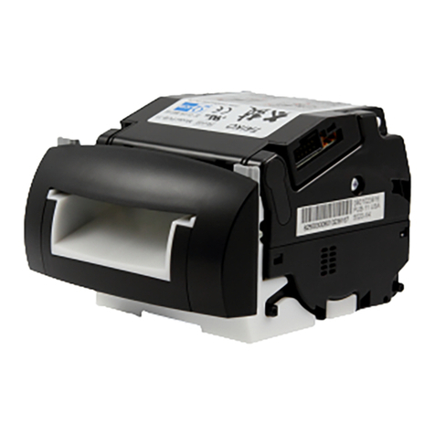

Table of Contents
P/N 960-100925R_Rev. A {EDP #186705} © 2010, Japan CashMachine Co, Limited
ii
Page
TBV™ Series Integration Guide
11 INTERNATIONAL COMPLIANCE......................................................................... 29
12 TECHNICAL CONTACT INFORMATION ............................................................. 30
Americas & Oceania......................................................................................................................30
JCM Global .................................................................................................................................30
Europe, Africa, Russia & Middle East ...........................................................................................30
JCM Europe GmbH.....................................................................................................................30
UK & Ireland ..................................................................................................................................30
JCM Europe (UK Office)..............................................................................................................30
Asia ...............................................................................................................................................30
JCM Gold (HK) Ltd. .....................................................................................................................30
Japan Cash Machine Co, Limited (HQ).......................................................................................30
13 INDEX .................................................................................................................... 31

P/N 960-100925R_Rev. A {EDP #186705} © 2010, Japan CashMachine Co, Limited
iii
TBV™ Series
Integration Guide
List of Figures Page
LOF
Figure 1 Transaction Based Validator Unit (TBV) .......................................................1
Figure 2 TBV Individual Major Component Names.....................................................2
Figure 3 Precautionary Symbols .................................................................................3
Figure 4 Unacceptable Banknotes ..............................................................................4
Figure 5 Fan-Flipping Banknotes ................................................................................4
Figure 6 Aligning Banknotes Edges ............................................................................4
Figure 7 M4 Screw Locations (Right & Left Sides) .....................................................7
Figure 8 M4 Screw Locations (Bottom & Rear Sides).................................................7
Figure 9 Removing the Cash Box .............................................................................13
Figure 10 Opening the Cash Box Door .......................................................................13
Figure 11 Removing a Jammed Banknote 1...............................................................13
Figure 12 Removing a Jammed Banknote 2...............................................................13
Figure 13 Removing a Jammed Banknote 3...............................................................14
Figure 14 TBV Sensor and Roller Cleaning Locations................................................15
Figure 15 TBV Operational Flowchart.........................................................................16
Figure 16 TBV USB Interface Schematic Diagram .....................................................17
Figure 17 TBV Photo-Coupler Interface Schematic Diagram .....................................18
Figure 18 TBV RS232 Interface Schematic Diagram..................................................19
Figure 19 TBV ccTalk Interface Schematic Diagram ..................................................20
Figure 20 TBV Banknote Acceptor’s Outside Dimensions..........................................27
Figure 21 TBV Banknote Acceptor’s Clearance Dimensions......................................28
Figure 22 TBV Banknote Acceptor Cash Box Outside Dimensions............................28

P/N 960-100925R_Rev. A {EDP #186705} © 2010, Japan CashMachine Co, Limited
v
TBV™ Series
Integration Guide
List of Tables Page
LOT
Table 1 TBV Software Number Specifications ............................................................3
Table 2 TBV Type Specifications ................................................................................3
Table 3 TBV Software Number Specifications ............................................................3
Table 4 TBV Technical Specification...........................................................................5
Table 5 TBV Environmental Specification ...................................................................6
Table 6 TBV Electrical Specification ...........................................................................6
Table 7 TBV Structural Specification...........................................................................6
Table 8 BNF Set Vend Denomination Switches DS1..................................................7
Table 9 Set BNF Buzzer Volume Switches DS2 .........................................................7
Table 10 TBV Set Vend Denomination Switches DS3 ..................................................7
Table 11 TBV Centering Mechanism & Select Comm Interface Switches DS4 ............8
Table 12 TBV Photo-Coupler/RS232 Interface Selection Switch DS5..........................8
Table 13 TBV Option Memory Selection Switches DS6................................................8
Table 14 LED Error Pattern Indications.........................................................................8
Table 15 TBV USB Interface Pin Assignments .............................................................9
Table 16 TBV Photo-Coupler Interface Pin Assignments ...........................................10
Table 17 TBV RS232 Interface Pin Assignments........................................................11
Table 18 TBV ccTalk Interface Pin Assignments ........................................................12
Table 19 TBV Sensor and Roller Type Cleaning Methods..........................................15
Table 20 LED Status/Error Code Condition ................................................................21
Table 21 Standard LED Error Codes ..........................................................................22
Table 22 LED Flash Reject Error Codes .....................................................................25

P/N 960-100925R_Rev. A {EDP #186705} © 2010, Japan CashMachine Co, Limited
1
TBV™ Series
Transaction Based Validator
Integration Guide
Revision A
Description
This section provides a general overview of the
Transaction Based Validator Unit (TBV) pictured
in Figure 1. This first section is designed to help
navigation through this guide with ease and
provides the following information:
• TBV Unit
• Component Names
• Primary Features
• Model Description
• Precautions
• Specifications
• Installation
• Connector Pin Assignments
• Preventive Maintenance
• Operational Flowchart.
• Standard Interface Circuit Schematics
• LED Diagnostics
• Unit Dimensions
• International Compliance
• Contact Information.
In order to make operation of this device easier and
make navigation within this manual simpler, the
following illustrations were used within the text:
• Safety Instructions, which need to be
observed in order to protect the operators and
equipment, have been written in bold text and
have been given the pictographs:
• Special Notes, which effect the use of the
Banknote Acceptor, have been written in italic
text and have been given the pictograph:
• Steps, requiring the operator to perform
specific actions are given sequential numbers
(1., 2., 3., etc).
1 GENERAL INFORMATION
TBV Unit
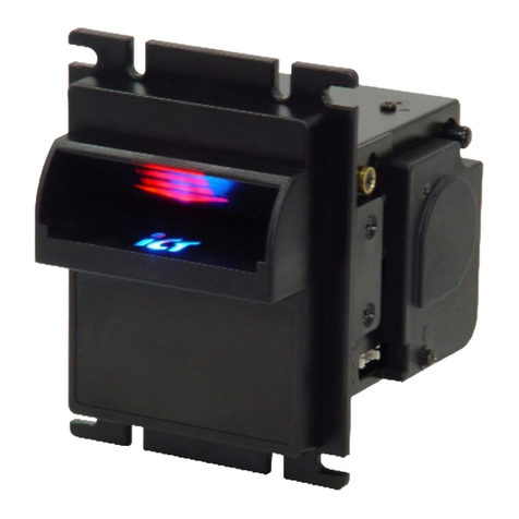
Figure 1 Transaction Based Validator Unit (TBV)

P/N 960-100925R_Rev. A {EDP #186705} © 2010, Japan CashMachine Co, Limited
2
Transaction Based Validator Integration Guide
Component Names
Figure 2 illustrates the TBV Component Names and Locations.
m
n
o
l
k
i
i
j
h
g
f
e
x
z
y
w
v
t
u
a
b
s
r
q
p
c
d
BNF
Transport
Frame
Cash Box
TBV Frame Unit
BNF Unit
(Front End View - No Bezel) (Base Side View)
Section
Section
Section
Figure 2 TBV Individual Major Component Names
a) Return Path Open/Close Cover
b) BNF Guide Latch
c) Bezel Section (Option)
d) Centering Release Port (Back Side)
e) Transport Section Front Guide Release Latch
f) Transport Section Release Lever
g) Denomination INHIBIT/ACCEPT Switches (DS3
[Set identical as DS1])
h) LED Indicator (Green/Yellow/Red)
i) USB Connector
j) Bezel LED Indicator Connector
k) Connector
l) Transport Section Rear Guide Latch
m)Interface Connector
n) Cash Box Lock Sensor Prism
o) Cash Box Lock Lever (Back Side)
p) Cash Box Release Lever
q) Cash Box Door Release Lever
r) Cash Box Handle
s) Thumb Twist Lock Knob
t) Pusher Plate
u) BNF Section Transport Release Lever
v) Denomination INHIBIT/ACCEPT Switches (DS1)
[Set identical as DS3])
w) Set BNF Buzzer Volume Switches (DS2)
x) TBV Centering Mechanism ON/OFF & Select
Communication Interface Switches (DS4)
y) TBV Photo-Coupler/RS232 Interface Selection
Switch (DS5)
z) TBV Option Memory Selection Switches (DS6)

P/N 960-100925R_Rev. A {EDP #186705} © 2010, Japan CashMachine Co, Limited
3
Transaction Based Validator Integration Guide
Primary Features
The TBV Series of Banknote Validator contains the
following primary features:
• Ability to accept 50 Banknotes at a time.
• High validation capability using the Centering
Mechanism and its own high precision Sensors.
• Able to stack up to 2,000 Banknotes in the
Plastic Cash Box.
Model Descriptions
Table 1 lists the Product Model Number
Descriptions.
Type Descriptions
Table 2 lists the Product Type Number
Descriptions.
Software Descriptions
Table 3 lists the various Software Number
Descriptions.
Precautions
The Figure 3 symbols are defined as follows:
1. (Type 1) Do not insert a torn, folded, or wet Ban-
knote, as this action may cause a Banknote jam
inside the Unit.
2. (Type 2) Do not expose the Unit to water. The
Unit contains several precision electronic devices
which can be damaged if water or liquid of any
kind is sprayed or spilled into the Unit.
3. (Type 3) Do not install the Unit into a dusty
environment. Dust may affect and degrade the
various Sensor’s performance.
U
SER
C
AUTIONS
Careful measures are taken in this product design to
ensure its quality, however, the following cautions
should be read and understood by all users in order
to confirm safe operation.
Installation Cautions
1. Do not allow the Unit to endure or operate at a
high temperature, in high humidity and/or in a
dusty environment.
2. Do not install the Unit into an area where exces-
sive vibration or shocks are present.
3. This equipment is not full warranted for outdoor
use. Be sure that the Host Machine contains
enough protection to avoid wet or dusty condi-
tions when installing it in both open-air and
indoor spaces.
4. Avoid exposing the Unit to direct Sunlight and/or
an incandescent Lamp illumination having a
Gradient Angle of 15 Degree or more, and an il-
lumination index of 3,000 Lux or less.
5. Insure that the Host Machine is designed for daily
operational access such as maintenance and/or
clearing a Banknote Jam.
Table 1 TBV Software Number Specifications
NoSoftware: TBV - * * * - * * *
No(1) (2)(3)(4) (5)(6)(7)
(1) Product Series Name
(2) Validate Sensor
1 = World Wide Type (Standard)
(3) Option Board
0 = None (Standard)
(4) Centering Unit
0 = Feature (Guide Width 60 - 85mm)
1 = None (USA Dollar 66mm only)*
*. The width dimensions of the BNF Section’s Guide, the Validation Section and the
Bezel are all of an equal size.
(5)
Accessory Unit
F = BNF Unit
G = Shutter Unit
0 = Reserved†
†. “0” = can be blank or omitted.
(6) Stacker Type
SH = Horizontal Stack Mechanism
LD = No Stack Mechanism
(7) Box Access
0 = Front Access Frame (Standard)†
B = Back Access Frame
Table 2 TBV Type Specifications
NoType: **** * - * * *
No(1)(2)(3)(4)(5)(6)(7)(8)
(1) Box Capacity
0 = No Cash Box
K = 2,000 notes
(2) Box Option
0 = Thumb Twist Lock Knob (Standard)
1 = Sealing
(3) ICB
0 = None (Standard)
1 = Optical Transport Method
(4)
Bezel Type
0 = None
1 = Plastic (Standard)
2 = Metal
(5) I/F Harness
1 = Standard
(6) Reserved
(7) Reserved
(8) Reserved
Table 3 TBV Software Number Specifications
NoSoftware: TBV-100 FSH * * * - * * * - V * .* *
No(A) (B) (C) (D)
(A) Software Model Name
(B) Denomination (Country)*
*. The Country Code is indicated by three (3) Alphabetical Characters following the
JIS Standard.
(C) Interface Protocol Name
(D) Software Version
Type 1 Type 2 Type 3
Figure 3 Precautionary Symbols

P/N 960-100925R_Rev. A {EDP #186705} © 2010, Japan CashMachine Co, Limited
4
Transaction Based Validator Integration Guide
6. When installing the equipment, connect the
Frame Unit to the Frame Ground of the Host
Machine.
7. Be sure to connect the Ground Wire of the Inter-
face Connector to the Chassis Frame Ground.
Mounting, Dismounting & Transportation
1. Be sure to turn the Power OFF before mounting
or removing the Unit from its permanent location.
Plugging or unplugging Connector Plugs from
their receptacles while the Power is ON may
cause damage to the Unit.
2. When reassembling a disassembled Unit Section,
ensure that each part is properly placed in its
original correct location.
3. Be sure to carry the Unit by both hands when
transporting it. Holding the Unit with one hand
may cause personal injury if the Unit accidently
becomes disassembled and falls apart.
4. Be careful not to use excessive outside pressure
on the Unit, or subject it to excessive vibration
during transportation.
5. Be careful not to exert external pressure on the
equipment without the Cash Box in place. Strong
pressure on the Frame may cause it to distort.
Preventive Maintenance
1. Be sure to turn the Power OFF before beginning a
Maintenance Procedure. The equipment produces
improper operating signals while in maintenance
mode that may cause personal injury.
2. If the Validator Section is dirty due to dust, for-
eign objects or other such debris adhering to it,
the Banknote acceptance rate will degrade. Clean
the Unit once a month to keep its performance
optimal and stable.
3. Use a soft, lint-free cloth, Cotton swab or Com-
pressed Air spray to clean dust and debris from
the Banknote transportation path.
4. Perform cleaning and maintenance regularly
when using the equipment in places where
excessive Automobile exhaust emission or
Cigarette Smoke may exist.
5. Be sure that the Guide or individual Unit Sections
are properly replaced in their correct location
following a maintenance procedure.
6. Do not redesign or disassemble the Unit. Un-
authorized use by inadequately trained personnel,
or use outside the original manufacture’s intended
use for operation voids the warranty.
Banknote Fitness Requirements
1. The following Banknote types may not validate
correctly, or can cause a Banknote jam and/or
damage to the Unit’s Transport path.
Banknotes exhibiting the conditions listed below
and illustrated in Figure 4 should be avoided:
• Having perforated or torn areas
• Having excessive folds
• Wet or damp
• Having excessive wrinkles
• Shabby/warn condition
• Adhering foreign objects and/or oil.
2. When inserting a bundle of Banknotes, Flip-over
and Fan-Flip the Banknotes; especially the new or
nearly new Banknotes in order to insert air in-
between them so they do not stick each other
prior to Bezel insertion (See Figure 5).
3. When inserting mixed, different sized Banknotes
into the Bezel, align one side of their rough edges
smoothly to one side of the bundle before insert-
ing them (See Figure 6).
Caution: Do not use Alcohol, thinner or
citrus based products for cleaning any
surfaces. The Lenses can become
clouded by chemical effect that may
cause acceptance errors.
Use a lint-free cloth soaked with purified
water and wrung dry to clean the
internal surfaces and BNF Rollers only.
Damaged Banknotes
Wrinkled Banknotes
Curled Banknotes
Folded or Partial Banknotes
Figure 4 Unacceptable Banknotes
Figure 5 Fan-Flipping Banknotes
Figure 6 Aligning Banknotes Edges

P/N 960-100925R_Rev. A {EDP #186705} © 2010, Japan CashMachine Co, Limited
5
Transaction Based Validator Integration Guide
Table 4 TBV Technical Specification
Acceptance Rate:
98% or greater
Note: The following banknote types are excluded:
a) Worn, dirty wet, stained, torn or excessively wrinkled Banknotes
b) Double (dual) Banknotes
c) Banknotes adhering Oil or Iron powder
d) Banknotes having folded corners or edges
e) Banknotes with excessive or inadequate magnetism or unclear graphics
f) Banknotes having the wrong cut dimensions or a printing displacement
g) Banknotes having excessive fold lines or specific Banknote processing
machine markings.
Bill Types Accepted: Long side: 110-170mm (4.33-6.69 in.)
Short side: 60-85mm (2.36-3.35 in.)
Barcode Coupon*:
Standard Specification
a) Read code interleaved: 2 of 5
b) Narrow Bar: 0.5mm-0.6mm (0.019-0.023 in.)
c) Wide Bar/Narrow Bar = 3:1
d) Characters: 18 Characters
e) Print Position: Middle (Divide a Coupon equally on the left, right, top and
bottom of the Coupon’s center)
f) Print Width: Wider than 10mm (0.39 in.)
Batch Up to 50 Notes
Insertion Direction: Banknote: Four-way
Barcode Coupon: Two-way (Only with Surface facing upward)
Processing Speed†:
Fixed Type:
•Banknote
– Approximately 1.3 seconds/note from Banknote insertion to Escrow.
– Approximately 1.7 seconds/note between the first and next Banknote insertion
during a sequential insertion operation.
•Barcode Coupon/Double Read‡
– Approximately 3.0 seconds/note from Banknote insertion to Escrow.
– Approximately 3.7 seconds/note between the next Banknote insertion during a
sequential insertion operation.
•Barcode Coupon/Single Read‡
– Approximately 1.3 seconds/note from Banknote insertion to Escrow.
– Approximately 2.0 seconds/note between the next Banknote insertion during a
sequential insertion operation.
Centering Model:
•Banknote
– Approximately 1.6 seconds/note from Banknote insertion to Escrow.
– Approximately 2.0 seconds/note between the next Banknote insertion during a
sequential insertion operation.
•Barcode Coupon/Double Read‡
– Approximately 3.5 seconds/note from Banknote insertion to Escrow.
– Approximately 4.2 seconds/note between the next Banknote insertion during a
sequential insertion operation.
•Bar-code Coupon/Single Read‡
– Approximately 1.6 seconds/note from Banknote insertion to Escrow.
– Approximately 2.3 seconds/note between the next Banknote insertion during a
sequential insertion operation.
Validation Method: Optical (6 Illumination, [Transmissive/Reflective]) and Magnetic
Diagnostic Indicators: LED Full Color
Escrow: 1 Note
Anti-stringing Mechanism: Optical Sensor & Pusher Mechanism
Interface: Photo-Coupler Isolation, RC232C, ccTalk, USB (Full Speed)
*. Refer to the specific “Bar Code Coupon Specification” Sheet for more details.
†. The time between the first Banknote insertion to the next Banknote sequential insertion operation.
‡. The Barcode Coupon Reading Specification can be changed by DIP Switch Settings.
2 SPECIFICATIONS
Technical Specifications

P/N 960-100925R_Rev. A {EDP #186705} © 2010, Japan CashMachine Co, Limited
6
Transaction Based Validator Integration Guide
Environmental Specifications
Electrical Specifications
Structural Specifications
Table 5 TBV Environmental Specification
Operating Temperature: +5ºC to +50ºC (41ºF to 122ºF)
Storage Temperature: -20ºC to +60ºC (-4ºF to 140ºF)
Relative Operating Humidity: 30% to 80% RH (non-condensed)
Relative Storage Humidity: 30% to 80% RH (non-condensed)
Visible Light Sensitivity: Avoid contact with direct sunlight (Interior lighting must be incandescent with a
Radiant Angle of 15 Degree or more having an Illumination index of 3000 Lux or less).
Installation: Indoors Only
Table 6 TBV Electrical Specification
Supply Voltage: 24VDC ±5% (Greater than 4.1A [100W] Recommend)
Current Consumption:
Standby = Approximately 0.2 A
Operation = Approximately 2.0 A
Peak = Approximately 3.3 A (Maximum 3 seconds)
Table 7 TBV Structural Specification
Weight: Approximately 12kg (26.46lbs)
Mounting: Horizontal
Outside Dimensions: See “TBV Entire Unit Outside Dimensions” on page 27 of this Guide.
Hydrothermal Condition Table
Humidity [%RH]
Temperature [ºC]
Allowable
and Humidity Range
Operating
Temperature
35ºC/80%
50ºC/30%

P/N 960-100925R_Rev. A {EDP #186705} © 2010, Japan CashMachine Co, Limited
7
Transaction Based Validator Integration Guide
3 INSTALLATION
Installation Process
Perform the following steps to install the TBV
Unit:
1. Place the TBV in its intended mounting location.
2. Bolt both the right and left sides of the TBV
Frame into its intended location using 8 Pan Head
Screws (4 on each side) from outside of the
Frame when this particular mounting configura-
tion is preferred (See Figure 7).
3. Remove the Cash Box and bolt the back side and
bottom side of the TBV Frame into its intended
location using 8 (eight) M4 Pan Head Screws
from the outside of the frame when this mounting
configuration is preferred (See Figure 8).
4. Connect the TBV Unit to the Host Machine using
a packaged Harness, and then supply the power.
DIP Switch Configurations
This portion provides the denomination value DIP
Switch Block settings for the TBV Unit.
Figure 7 M4 Screw Locations (Right & Left Sides)
NOTE: The maximum length of the M4 Pan Head
Screws should be 4mm plus the thickness of the
Cabinet or mounting Bracket (See “TBV Entire
Unit Outside Dimensions” on page 27 of this
Guide to confirm each Screw pitch condition).
Figure 8 M4 Screw Locations (Bottom & Rear
Sides)
Table 8 BNF Set Vend Denomination Switches
DS1
Switch No. Switch ON Switch OFF
1VEND 1 INHIBIT VEND 1 ACCEPT
2VEND 2 INHIBIT VEND 2 ACCEPT
3VEND 3 INHIBIT VEND 3 ACCEPT
4VEND 4 INHIBIT VEND 4 ACCEPT
5VEND 5 INHIBIT VEND 5 ACCEPT
6VEND 6 INHIBIT VEND 6 ACCEPT
7VEND 7 INHIBIT VEND 7 ACCEPT
8N/A*
*. Not Applicable (N/A). Never Switched to ON.
OFF (Fixed)
Table 9 Set BNF Buzzer Volume Switches DS2
Switch
No. Switch ON Switch OFF
1N/A*
*. Not Applicable (N/A). Never Switched to ON.
OFF (Fixed)
2 Performance Buzzer ON Performance Buzzer
OFF
3ONFixed N/A*
4 N/A* OFF (Fixed)
Table 10 TBV Set Vend Denomination Switches
DS3
Switch No. Switch ON Switch OFF
1 VEND 1 INHIBIT VEND 1 ACCEPT
2 VEND 2 INHIBIT VEND 2 ACCEPT
3 VEND 3 INHIBIT VEND 3 ACCEPT
4 VEND 4 INHIBIT VEND 4 ACCEPT
5 VEND 5 INHIBIT VEND 5 ACCEPT
6 VEND 6 INHIBIT VEND 6 ACCEPT
7 VEND 7 INHIBIT VEND 7 ACCEPT
8N/A*
*. Not Applicable (N/A). Never Switched to ON.
OFF (Fixed)
NOTE: To install the TBV Unit into a Host
Machine, affix at least two of the four side
dimension in place.
ON
OFF
DS1
OFF DS2
ON
NOTE: When installing the BNF Section onto the
TBV-100 Unit, DIP Switch #3 settings will have no
effect. In this case, DIP Switch #1 on the BNF
Section must therefore be used for setting the
required denomination.
DS3
OFF
ON

P/N 960-100925R_Rev. A {EDP #186705} © 2010, Japan CashMachine Co, Limited
8
Transaction Based Validator Integration Guide
Primary LED Indications
The following Table 14 Color LED indications
occur during various TBV operating and error
conditions.
Table 11 TBV Centering Mechanism & Select
Comm Interface Switches DS4
Switch No. Switch ON Switch OFF
1 Fixed Model Centering Model
2Barcode Coupon
Single Read*
*. When using the “Single Read” Barcode Coupon setting, its Checksum may have
to be changed to improve reading accuracy. The “Double Read” setting however,
has a higher reliability and read accuracy by the TBV Validation System.
Barcode Coupon
Double Read*
3†
†. Match each setting to equal the setting of DIP Switch DS5 Switch #1.
4†
Table 12 TBV Photo-Coupler/RS232 Interface
Selection Switch DS5
Switch No. Switch ON Switch OFF
1*
*. Match each setting to DIP Switch DS4 Switches #3 & #4.
Photo-Coupler RS232
Table 13 TBV Option Memory Selection Switches
DS6
Switch No. Switch ON Switch OFF
1N/A*
*. Not Applicable (N/A). Never Switched to ON.
OFF (Fixed)
2 N/A* OFF (Fixed)
Table 14 LED Error Pattern Indications
Mode TBV LED
Indication TBV Condition
Normal
Mode
Lit Blue Stand-by (Waiting for a Banknote
insertion)
Lit Yellow Waiting for a Host Machine
Command
OFF
(Extinguished)
BUSY (Processing Validation) or an
INHIBIT Command
Lit Green Cash Box Near Full detection
Yellow Flashes Internal processing (Self download:
Transport Section →BNF Section)
Yellow Flashes*
*. Returns to Stand-by Mode after clearing the error condition (See “Standard
Error Codes” on page 22 of this Guide to resolve the error type).
Banknote Jam or Setting malfunction
Red Flashes†
†. Returns to Stand-by Mode from a RESET Command, or after clearing the error
condition (See “Standard Error Codes” on page 22 of this Guide to resolve the
error type).
Abnormal (ABN) Error
Download
Mode
Green Flashes Waiting for a Download
Yellow Flashes Downloading
Lit Blue Download completed
OFF
DS4
ON Set Identical
I/F Selection Switch #3 Switch #4
RS232 OFF OFF
Photo-Coupler ON OFF
ccTalk OFF ON
ccTalk with Encryption ON ON
RS232
Photo-Coupler
DS5
ON
OFF
ON
OFF DS6

P/N 960-100925R_Rev. A {EDP #186705} © 2010, Japan CashMachine Co, Limited
9
Transaction Based Validator Integration Guide
4 CONNECTOR PIN ASSIGNMENTS
Table 15 through Table 18 list the TBV Pin Assignments respectively.
Table 15 lists the TBV USB Interface Pin Assignments.
Table 15 TBV USB Interface Pin Assignments
Back Side View
Socket (Transport Unit Side): DR1P026SA1 (JCM)
Socket (Frame Unit Side): DR1R026PA1 (JCM)
Contact (Frame Unit Side): D02-22-22P-10000 (JAE) (Pole# 1,9,18 & 26)
UL3443 AWG#24 Ø1.3mm or less
D02-22-26P-10000 (JAE) (Poles except 1,9,18 & 26)
UL1061 AWG#26 Ø1.1mm or less
Pin No. Signal Name I/O*
*. I/O (input/output) is the Terminal as viewed from the Banknote Validator’s backside.
Function
124V DC (POWER) -+24V DC Power Supply
2M-RESET IN Acceptor Reset Signal Input Line
3USB+ IN/
OUT USB Communication Input/Output Signal Line
4USB- IN/
OUT USB Communication Input/Output Signal Line
5USB GND USB Communication Ground (0V DC)
6 - No Connection
7 - No Connection
8 - No Connection
924V DC (POWER) +24V DC Power Supply
10 -No Connection
11 -No Connection
12 +12V (Opto) +12V DC (or +5V DC)
13 USB Vbus USB Communication Vbus Signal Line (+5V DC)
14 -No Connection
15 -No Connection
16 -No Connection
17 -No Connection
18 Power GND 0V DC Power Supply
19 -No Connection
20 -No Connection
21 -No Connection
22 -No Connection
23 -No Connection
24 -No Connection
25 -No Connection
26 Power GND 0V DC Power Supply
Frame
GNDFrame Ground (Be sure to connect it to the Chassis Frame)
Frame Ground

P/N 960-100925R_Rev. A {EDP #186705} © 2010, Japan CashMachine Co, Limited
10
Transaction Based Validator Integration Guide
Table 16 lists the TBV Photo-Coupler Interface Pin Assignments
Table 16 TBV Photo-Coupler Interface Pin Assignments
Back Side View
Socket (Transport Unit Side): DR1P026SA1 (JCM)
Socket (Frame Unit Side): DR1R026PA1 (JCM)
Contact (Frame Unit Side): D02-22-22P-10000 (JAE) (Pole# 1,9,18 & 26)
UL3443 AWG#24 Ø1.3mm or less
D02-22-26P-10000 (JAE) (Poles except 1,9,18 & 26)
UL1061 AWG#26 Ø1.1mm or less
Pin No. Signal Name I/O*
*. I/O (input/output) is the terminal as viewed from the Banknote Validator’s backside.
Function
124V DC (POWER) -+24V DC Power Supply
2M-RESET IN Acceptor Reset Signal Input Line
3 - No Connection
4 - No Connection
5 - No Connection
6 - No Connection
7 - No Connection
8 - No Connection
924V DC (POWER) +24V DC Power Supply
10 -No Connection
11 Serial OUT OUT Serial Communication Output Signal Line TXD
12 +12V (Opto) Interface Power Supply (+12V DC)
13 -No Connection
14 -No Connection
15 -No Connection
16 -No Connection
17 -No Connection
18 Power GND 0V DC Power Supply
19 Opto GND Photo-coupler Communication Ground
20 Serial IN IN Serial Communication Input Signal Line RXD
21 -No Connection
22 -No Connection
23 -No Connection
24 -No Connection
25 -No Connection
26 Power GND 0V DC Power Supply
Frame
GNDFrame Ground (Be sure to connect it to the Chassis Frame)
Frame Ground

P/N 960-100925R_Rev. A {EDP #186705} © 2010, Japan CashMachine Co, Limited
11
Transaction Based Validator Integration Guide
Table 17 lists the TBV RS232 Interface Pin Assignments
Table 17 TBV RS232 Interface Pin Assignments
Back Side View
Socket (Transport Unit Side): DR1P026SA1 (JCM)
Socket (Frame Unit Side): DR1R026PA1 (JCM)
Contact (Frame Unit Side): D02-22-22P-10000 (JAE) (Pole# 1,9,18 & 26)
UL3443 AWG#24 Ø1.3mm or less
D02-22-26P-10000 (JAE) (Poles except 1,9,18 & 26)
UL1061 AWG#26 Ø1.1mm or less
Pin No. Signal Name I/O*
*. I/O (input/output) is the terminal as viewed from the Banknote Validator’s backside.
Function
124V DC (POWER) -+24V DC Power Supply
2M-RESET IN Acceptor Reset Signal Input Line
3 - No Connection
4 - No Connection
5 - No Connection
6 - No Connection
7 - No Connection
8 - No Connection
924V DC (POWER) +24V DC Power Supply
10 GND RS232 Interface Ground
11 Serial OUT OUT Serial Communication Output Signal Line TXD
12 +12V (Opto) +12V DC (or +5V)
13 -No Connection
14 -No Connection
15 -No Connection
16 -No Connection
17 -No Connection
18 Power GND 0V DC Power Supply
19 -No Connection
20 Serial IN IN Serial Communication Input Signal Line RXD
21 -No Connection
22 -No Connection
23 -No Connection
24 -No Connection
25 -No Connection
26 Power GND 0V DC Power Supply
Frame
GNDFrame Ground (Be sure to connect it to the Chassis Frame)
Frame GroundFrame Ground

P/N 960-100925R_Rev. A {EDP #186705} © 2010, Japan CashMachine Co, Limited
12
Transaction Based Validator Integration Guide
Table 18 lists the TBV ccTalk Interface Pin Assignments.
Table 18 TBV ccTalk Interface Pin Assignments
Back Side View
Socket (Transport Unit Side): DR1P026SA1 (JCM)
Socket (Frame Unit Side): DR1R026PA1 (JCM)
Contact (Frame Unit Side): D02-22-22P-10000 (JAE) (Pole# 1,9,18 & 26)
UL3443 AWG#24 Ø1.3mm or less
D02-22-26P-10000 (JAE) (Poles except 1,9,18 & 26)
UL1061 AWG#26 Ø1.1mm or less
Pin No. Signal Name I/O*
*. I/O (input/output) is the terminal as viewed from the Banknote Validator’s backside.
Function
124V DC (POWER) -+24V DC Power Supply
2M-RESET IN Acceptor Reset Signal Input Line
3 - No Connection
4 - No Connection
5 - No Connection
6 - No Connection
7 - No Connection
8 - No Connection
924V DC (POWER) +24V DC Power Supply
10 GND ccTalk Interface Ground
11 -No Connection
12 +12V (Opto) Interface Power Supply +12V DC
13 -No Connection
14 -No Connection
15 -No Connection
16 -No Connection
17 ccTalk PULL UP ccTalk Communication Signal Line Pull Up
18 Power GND 0V DC Power Supply
19 -No Connection
20 -No Connection
21 -No Connection
22 -No Connection
23 -No Connection
24 -No Connection
25 ccTalk IN/
OUT ccTalk Communication SIgnal Line
26 Power GND 0V DC Power Supply
Frame
GNDFrame Ground (Be sure to connect it to the Chassis Frame)
Frame Ground
This manual suits for next models
1
Table of contents
Other JCM GLOBAL Bank Note Validator manuals

JCM GLOBAL
JCM GLOBAL DBV Series Quick setup guide

JCM GLOBAL
JCM GLOBAL TBV-100 FSH User manual

JCM GLOBAL
JCM GLOBAL VEGA Series User manual

JCM GLOBAL
JCM GLOBAL Taiko PUB-7 User manual

JCM GLOBAL
JCM GLOBAL UBA Pro Series User manual

JCM GLOBAL
JCM GLOBAL iVIZION2 Series Quick setup guide

JCM GLOBAL
JCM GLOBAL RDM-100 Series Quick setup guide

JCM GLOBAL
JCM GLOBAL WBA Series User manual