Jeio tech IB-05G User manual

Page 1
Operation manual
[INCUBATOR]
Model : IB-05G / 15G / 25G
Manual No : 00HAA0001141 ( Version : 5.0 )
This operation manual describes the important subjects to maintain
the product’s functions and to use it safely. Especially, be sure to
read <Safety Precaution> carefully before you use this equipment.
Please keep this manual close to the equipment to use it after
reading through it once. Please place it where the new user can
find it easily for the safety use when you hand over or lend the
equipment to others.

Page 2
Thank you for purchasing Jeio Tech’s product.
This operation manual forms a definition of warning marks
according to the level of importance and danger in order to use
the product safely and correctly and prevent the users from
accidents or injuries. Hence, please use the product in
accordance with the instructions.
Safety Notice
1. Caution
This product can cause a big accident in case of improper use of inflammable
and combustible solvents in the chamber. Also, operation in the high
temperature might cause a mechanical trouble and quality deterioration due to
the function and the characteristic of the product.
Safety Precautions
“Danger” means that the user may have
serious damage and even die by improper
handling on this unit.
“Warning” means that the user may have
serious damage by improper handling on this
unit.
“Caution” means that the user may have minor
damage and unit may have physical damage
by improper handling on this unit.

Page 3
Although Jeio Tech thoroughly investigates the possibilities of
dangerous situations from using the product, it is not possible to
know every single danger. Hence, precautions described in this
manual do not cover all the dangerous conditions.
However, you can operate this product safer when you follow the
directions in this manual. Please, be sure to pay attention to the
directions and be cautious so that a mechanical trouble or an
accident would not be occurred.
2. Warning mark of product
The most important thing of the warning is a warning label attached to the
product. It is located in front of the door.
Be fully aware of the warning contents during operation.
※ Please change to the new warning label when it is unreadable from wearing out. Please
request the new label to us.
Copyright 2007 Jeio Tech Co., Ltd. ALL RIGHT RESERVED.

Page 4
CONTENTS
1. Use and Feature ……………………………………………… 5
2. Installation ……………………………………………………………… 6
3. Notice …………………………………………………………………… 7
4. Name of the parts ………………………………………………… 8
5. Operating Controller ………………………………………………… 11
6. Maintenance ………………………………………………………… 18
7. Dealing with Abnormal Condition ………………………………… 19
8. Guarantee …………………………………………………………… 20
9. Equipment Disuse …………………………………………………… 20
10. Specifications ……………………………………………………… 21
11. Install lab tracer …………………………………………………… 22
12. How to use lab tracer …………………………………………… 23

Page 5
1. Use and Feature
1) Use
(1) This Incubator is used for cultivation of thermopile micro organism and normal micro
organism like e coli and bacteria.
(2) This Incubator is used for tissue of plant and animal, activating sperm and egg and
determination of germfree of sterilized culture medium.
(3) This Incubator is good for constant temperature test like test of plant storage, environment
variation.
2) Feature
(1) This multi purpose incubator for Biotechnology, pharmacy, medical, chemical, and biology.
This unit has firstly developed CLS (Custom Logical Safe)-Control system for convinces in
use and safety to user.
(2) CLS-Control System means “Control system which has logical safety device specialized for
individual model”. Laboratory must have Thermal safety secure because there are a lot of
inflammable reagent. This system is highest safety secure control device (patent No.
0397583, 0328729) and makes the unit suitable for this kind of environment.
(3) This unit is designed to stop the Heater and Blower in order to protect the user from heat
when its door opened while it works.
(4) This unit has insulation for high temperature in the outside of the inner chamber and inside
of the door and also has Chamber Silicone door for high temperature therefore insulation is
perfect and heat lose is very low.
(5) Triple observing window is good for insulation and observe. This is Optional
(6) Uniform temperature in the chamber is made by special design.
(7) Safety circuit is used to protect the instrument from over charge and over temperature of the
heater.

Page 6
2. Installation
(1) Scope of delivery.
Main body(1set), Operation manual (1EA), Fuse (2EA), Shelf(2EA), Shelf guide(4EA) ,
Communication CD(1EA), RS-232 Communication cable(1EA)
(2) This unit will work correctly on proper power supply. Please check power supply and ID
Plate information are the same. User must use power supply connected earth and power
cord must be connected to wall outlet supplying ground point.
We don’t have any responsibility for accident and lose of personal and asset if the ground earth is not
connected.
(3) Please install the unit in the flat place where prevent vibration and shock.
(4) Please let the unit avoid heat source and direct sun light and let the unit located in ambient
temperature range in 5°C ~ 40°C relative humidity lower than 80%.
(5) Please don’t install the unit where water and organic solvent is easily penetrates in the unit.
They cause short circuit.
(6) Please don’t install the unit in dangerous place. (Where there are flammable gas and
explosive material)
(7) Please secure enough space for installation because the door of it opened 180°.
(8) Do not install near to instruments of strong high-frequency ( high-frequency welding
machine, sewing machines, SCR Controller for big capacity)
(9) This unit is quite heavy. Please move the unit with proper moving tool or 2 people together.
(10) Power cord should includes Ground terminals when installing the instrument.
(11) Install the instrument near to consents for easy usage.
Please think about the safety of user and instrument when you find out a place to install.

Page 7
3. Notice
(1) Please don’t touch Power cord and electric part with wet hand.
(2) Please don’t put explosive and flammable chemicals (Alcohol, Benzene and etc) inside of
the oven.
(3) The samples inside of the oven are very hot when the oven is works and for a while after it
stops. Please take safety glove when you touch samples.
(4) Please don’t set flammable materials near by oven.
(5) Please don’t pour water on the unit directly when you clean the unit.
(6) Please don’t put some conductive and flammable materials through ventilation or power
supply port. It is dangerous and causing fire and electric shock.
(7) Circuit and electric component used in this unit are developed by Jeio tech. Please don’t try
to repair by yourself. Wrong combination of electric part may cause fire. You must ask to
official Jeio tech dealer or distributor in your region.
Don’t put explosive and flammable materials inside of the Chamber.

Page 8
4. Name of the parts
(1) Main body
Made by iron plate and painted.
(2) Ventilating hole
It changes air volume of ventilation. It’s very hot, please wear safety glove when you need
to adjust it. The safety gloves must be dry. Wearing wet gloves cause burning and electric
shock.
(3) Shelf level adjustor
Shelf level is easily adjustable by the size of sample.
(IB-05G→8 levels, IB-15G→12 levels, IB-25G→14 levels)
(4) Shelf
It’s made by Stainless steel wire. It’s easy to clean and ventilation is good. The surface of
it is electrically polished therefore it has beautiful face good anti-corrosion.
(5) Door
There are air barrier between door surface and insulation of the door. Therefore the surface
of the door is cool.

Page 9
(6) Inner door
User can observe the inside of the chamber through this transparent and made by
reinforced glass inner door. This prevent environment inside of the chamber from exposure
to outer air then polluted. turn the handle of glass door to clockwise rotation to close the
door and to the opposite way of clockwise rotation to open the door.
(7) Door Handle
It is Door handle for door opening.
(8) Magnetic Packing
Used for shock absorber and double- air tightness.
(9) Chamber
It’s made of stainless steel and there are Blower, Heater, Temp. sensor and Temp.
regulator inside of the chamber.
(10) Temperature Controller
This has a Micro processor (CPU) which has Digital PID Auto tuning function. It also has
temperature compensation function for temperature sensor and the highest class safety
level control system such as heating volume controller.
(11) Over temp. Limit.
If the heater temperature rises higher than set temperature it cut the power of the
temperature controller, makes the over temperature LED blinking and alarming beep
sounds. If you resume the operation, please set knob of it about 15% higher than set
temperature and press Start/Stop switch ones then check run led of temperature controller
is on.
(12) Inner Door packing
A silicone rubber for high temperature keeps high air sealing.
(13) Control panel
Controller and electric component are there.

Page 10
(14) Main switch & Fuse
This is the switch for main power. Fuse protects the instrument from electric shock. Please
check out correct power supply when you replace Fuse.
(15) Communication port
User can monitor and remote control this unit by PC. Data print out through PC printer is
also available. The unit can be connected to PC’s com1 and com2 port through RS-232C
protocol cable.
(16) Foot
This adjusts level of the instrument.
(17) Inner Door limit switch
It’s installed inside of the unit. The Logic IC of this switch put off the main switch. This cut
off all 2 phase currency in the instrument therefore heater and blower stops for safety of
user. Door LED blinking to indicate the door is opened. If the door is opened more than 1
minute then the alarming buzzer sound in order to inform the user that the door is opened
for a while. Run LED is on by closing the Door and put button.

Page 11
5. Operating Controller
1) Features
(1) CLS-Control System temperature and heater output are controlled in Main CPU which
can do precise PID calculation. All control for safety is conducted by selective
functional Logic IC which is installed separately. This is designed to conduct safety
performance against any electric and electronic shock on the unit.
(2) CLS-Control System shuts down all 2 phase power supply to each part immediately
and informs user instability by audio and visual device then keeps in safe mode until all
instability conditions removed.
(3) CLS-Control System gives user two choice, one is resume operation of the unit and
another is keeps the unit in standstill when the unit operation were terminated by
power failure and then recovered.
(4) CLS-Control System, the safety device designed to keep very small amount of
currency (only 5V, 10mA) in contact point. This makes durability of contact point very
long.
2) Name and operation
The instrument includes CPU for possible digital PID-Auto tuning software and the best safety
controlling device for temperature- compensating function for Pt-100Ω sensor and heating
control.

Page 12
(1) HEATER LED
It shows Heating function is “ON”
(2) Auto Tune LED
Flickering begins on Auto-tuning.
(3) Wait On Timer LED
This is the LED indicating operation start time. The LED is blinking when the timer works and
the LED off when the timer is in waiting condition.
(4) Wait Off Timer LED
This is the LED indicating operation stop time. The LED is blinking when the timer works and
the LED off when the timer is in waiting condition.
(5) Door open LED
LED is on by opening the door.
(6) Over heating alarm LED
If the heater temperature rises higher than set temperature it cut the power of the
temperature controller, makes the over temperature LED blinking and alarming beep
sounds. If you resume the operation, please set knob of it about 15% higher than set
temperature and press Start/Stop switch ones then check run led of temperature
(7) Temp. button.
This button is for temperature setting.
(8) Timer button.
This button is for timer setting.
(9) Up button.
This button is for increasing set value.
(10) Down button.
This button is for decreasing set value.
(11) Enter button.
This button is for saving value after varying set value.
(12) Start/Stop button.
This button is for start/stop of unit and for resuming operation after removing some
unstable factors when operation is terminated because of it.

Page 13
(13) Lock button.
This is to lock controller buttons.
(14) Auto Tune button.
The auto tune begins if you press this button for 1 second.
(15) RUN LED
This LED indicates Work/Stop state of unit. It turns on when the unit runs and turns down
when the unit stops.
(16) SV display
This display is for showing set temperature and showing remaining time when the timer
function is activated.
(17) PV display
This display is for showing present temperature.
3) Temperature setting way
(1) Press button. Set temperature value (SV) is blinking. This means you can vary set
value.
(2) Press button to vary digit number and press button when you save the
value.
(3) It goes back to previous state without saving if you don’t touch any button for 10 seconds.
(4) Press button again when it is in SV set state then following additional functions are
activated
Page 14
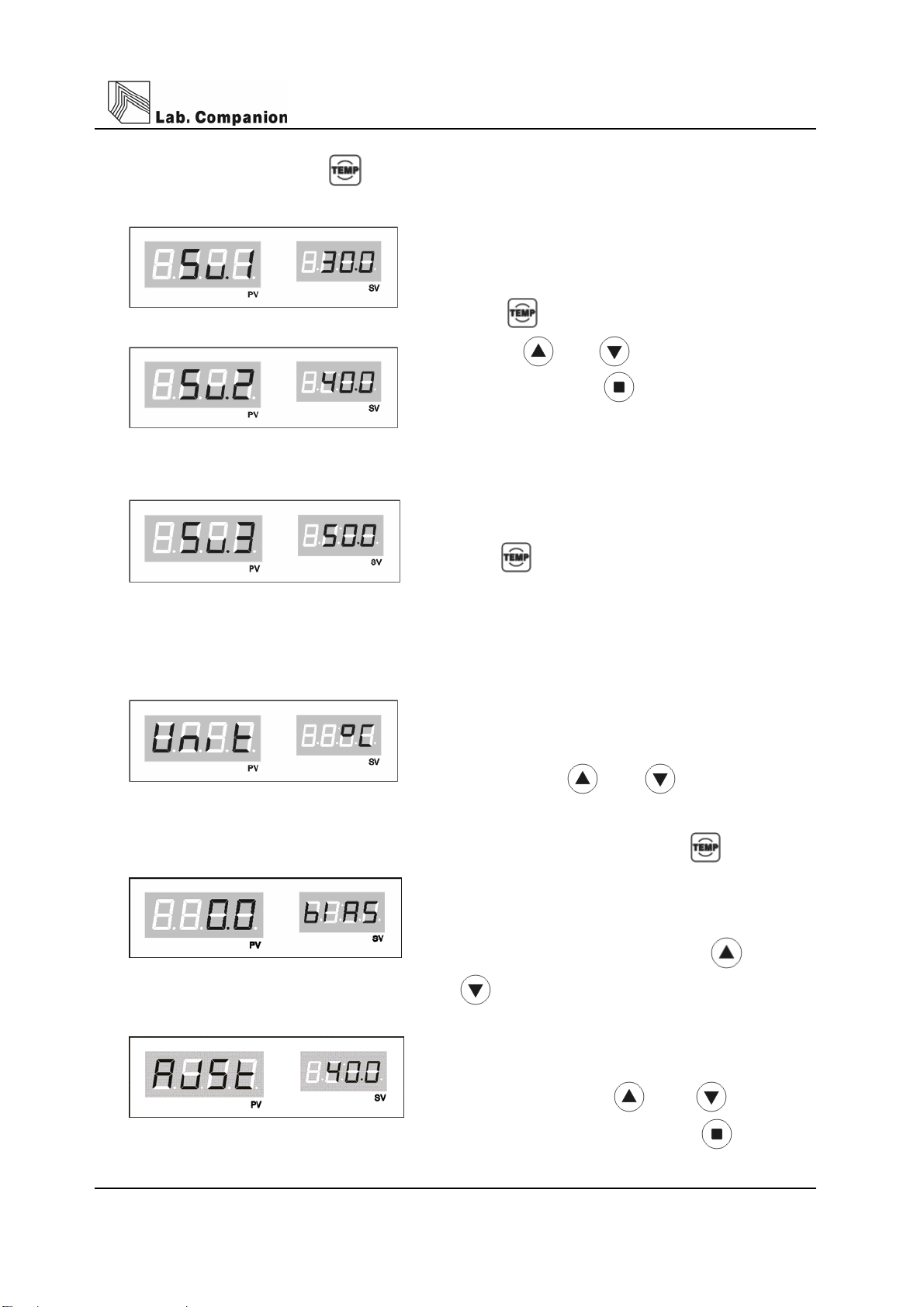
4) Additional function of button
(1) Favorite values can be stored at Sv.1, Sv2, Sv3
for each operation.
Press 2 times and set temp. values by
pressing and , and conclude the
setting by pressing
Set temperature is saved on memory and set
temperature varies Sv1, Sv 2, Sv 3 are applied
the same.
Press button repeatedly then Sv1, Sv2,
Sv3 are shown and temperature unit set mode
shown by pressing 5 times repeatedly.
(2) This is a function vary the unit of temperature
value.
Initial display is ℃ and it can be varied ℃ and
℉ by pressing and buttons.
(3) Next mode is shown by pressing 6 times.
This compensates the temp. value errors.
Requested values are put on PV display. Move
to the next mode by pressing and
00000buttons.
PV is put on the SV display and can be set
as exactly as shown on thermometer. Set the
value by pressing and , and
conclude the setting by pressing

Page 15
5) How to set Timer.
(1) Press button.
Timer (On Timer / Off Timer) is shown on PV and time is shown on SV display. Set time by
pressing button and Save by pressing button.
(2) W/ON LED turns on with Beep sound after finishing wait on timer set.
(3) Press button two times. You can set wait off timer.
Set time by pressing button and save and finish by pressing button.
(4) W/OFF LED turns on with Beep sound after finishing wait on timer set.
(5) The function of Timer is as follows.

Page 16
Wait on Timer Wait off Timer
Temperature
Time
☞ Wait On Timer
- The unit begins to work when the time programmed into ‘Wait On’ is attained.
- Maximum is 99hr 59mim. and minimum is 1min.
☞ Wait Off Timer
- The unit stops when the time programmed into ‘Wait Off’ is attained.
- Combination of Wait On Timer & Wait Off Timer.
- The unit works as picture above
(6) Set off Wait on/off Timer
Press button one (Wait on Timer) or two (Wait off Timer) times and set Z(0) by
pressing and finally press to set off.
6) Additional function of button.
The following Auto Run function is shown by pressing button thee times repeatedly.
(1) This is for compensating function after power failure.
If you set yes the unit will run or else the unit will not run after power failure situation
finished.

Page 17
7) Auto Tuning
Perform Auto Tuning in order to get precise and rapid temperature control. PID value saved
automatically after Auto Tuning.
(1) Set temperature you want.
(2) Press button for a while(3seconds) then Auto Tune shown display like right hand side
picture and A/T LED blinking.
(4) RUN LED is on by pressing button and Auto Tune is working with flickering A/T LED.
(5) Auto Tune time is various according to installed environment. LED turns off after finishing
Auto Tune and Present temperature & Set temperature meet.
8) Key Lock
This is to lock controller buttons.
(1) Press button for a while (3seconds), then Lock function is set with Beep sound and
the unit wouldn’t corresponding any more key pressing.
(2) In order to deactivate this function please Press button for 3 seconds again.
(3) This protects improper pressing of the controller buttons while operation.

Page 18
6. Maintenance
(1) Turn off the main power switch and pull out a power plug from wall outlet.
(2) Remove all liquid in the bath.
(3) Wash with soft cloth containing neutral detergent.
(4) Wash with soft cloth containing distilled water.
(5) Dry with dry cloth.
(6) Don’t use organic solvent.
(7) If user try to clean this unit with other method not mentioned on this manual please contact
us in order not to damage to the unit.
(8) Put on Safety glove for harmful chemicals and Safety Mask for harmful gas and then wash
out pollutant with dried cloth when harmful chemicals and gases are spread out on the unit.

Page 19
7. Dealing with Abnormal Condition
1) Check points when the unit doesn’t work.
(1) Check out power supply.
(2) Check out fuse if off.
(3) Check out Run LED on display is off.
Please press Start / Stop button if it is off.
(4) Please check the power is out.
2) Malfunction check list.
Malfunction symptom What to check and what to do.
Buzzer sound
continuously(1)
If Door is opened, Press START/STOP Switch once and check out Run
LED turns on.
No temperature
control.
Check if there are machines generating strong high frequency noise
near by the unit.
Check if Some contaminants are in the control panel.
Do Auto tune again.
Air circulation is not
made in the chamber
Check the door switch (open and close the door 2~3times)
Check the blower works correctly
Abnormal sound
Check the Impeller of blower is OK inside of the chamber.
Open the back plate of the instrument and Check the Impeller of Blower
touches any part.
No power
Check the Main power Switch is on.
Check the power supply is on in the room.
Check the power failure.
Check the fuse is OK
Temperature wouldn’t
rise
Check the RUN LED is on.
Press the START/STOP Switch once if the RUN LED is off.
Check the door is opened.
Buzzer sound
continuously(2)
Check the Over temp. limit is set lower than current set value of the
temperature.
If it is, please set the value of the Over temp. limit at least 15% higher
than PV.
Press the START/STOP Switch once and the check the RUN LED.
☞ If you can’t recover the instrument please call a repair service.

Page 20
8. Guarantee
1) Warranty service duration
It covers for 1 year since you purchase the unit and then after the duration you need to pay for
service parts.
You can get faster and precise service by telling us the information as below.
*Date of Purchase
*Serial number
*Symptoms and regions of break-down
*Using environment
2) The case user can’t get warranty service.
*wrong operation by users.
*Wrong usage and management.
*Wrong remodeling and repair by users.
*Break down by natural calamity.
*Different usage from operation manual
9. Equipment Disuse
keeps an abolition way if disposes of a product or parts, and please dispose of abolition.
An abolition way of main configuration parts
Configuration
Parts
Model Weight (Kg) Size (mm) An abolition way
Main Body IB-05G 45Kg 595×555×745
Main Body IB-15G 55Kg 675×605×855
Main Body IB-25G 62Kg 805×655×885
commits to a businessman
treating a waste, and
please dispose of abolition.
This manual suits for next models
2
Table of contents
Other Jeio tech Laboratory Equipment manuals


