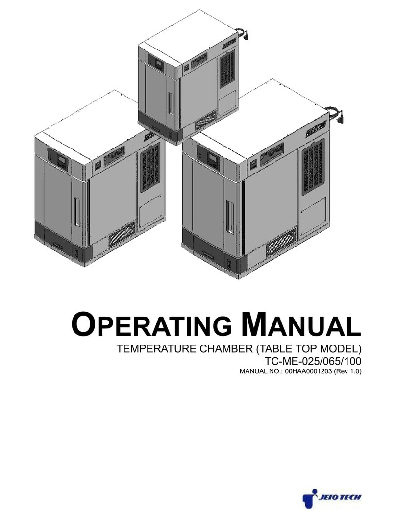
Jeio tech OV-11 User manual

Service Manual
(Model : OV-11 / 12)
작성일자 2008-3-31
개정일자 2008-3-31
개정번호 Rev.(0)

- 2 -
INDEX
1. Service
1-1. Temperature
- Temp doesn’t increase
- Temp trembling
- Variation Cause
- Temp keeps rising
1-2. Power
- No Power
- Power shut off during operation
- Power shut off after turning on
1-3. DISPLAY
- Push button error
- Display error
1-4. Door
- Can’t close door
1-5. Current leakage.
- Current breaker active.
1-6. Communication
- Can’t connect.
1-7. Vacuum
- How to check vacuum leaking point.
- Can’t get vacuum status.
- Vacuum leakage.
2. Disassembly and Inspection
2-1. Disassembly
2-1-1. Side Cover panel disassembly.
2-1-2. Door packing disassembly.
2-1-3. Main board PCB disassembly.
2-1-4. SSR disassembly.
2-1-5. Relay disassembly.
2-1-6. Noise Filter disassembly.
2-1-7. 3 way valve disassembly.
2-1-8. Heater disassembly.
2-1-9. Display PCB disassembly.
2-1-10. Temperature control Sensor disassembly.
2-1-11. High Temp Limit Sensor disassembly.
2-1-12. Keeper disassembly.
2-1-13. Communication Board disassembly.
2-2. Inspection
2-2-1. Main Board Relay output Inspection.
2-2-2. Main Board Heater output Inspection.
2-2-3. Main Board AC input Power Inspection.
2-2-4. Heater short circuit Inspection.
2-2-5. Heater leakage Inspection.
2-2-6. Noise Filter error Inspection.
2-2-7. Main Power Switch error Inspection.
2-2-8. SSR error Inspection.
2-2-9. Wire snaps Inspection.

- 3 -
1. Service
1-1. Temperature
Classification Symptom Service Factor
Temperature Temp doesn’t increase Heater Malfunction
Check point
1. After setting 100℃ then press Start Button to operate the unit.
2. Check the Heater temp itself. (Be careful heater is very hot.)
3. Measure resistance checking positive terminal of heater using of the multi meter.
Æ If resistance doesn’t measure, it is a malfunction
Solution
- Replace a heater.
1. “2-1-8. Heater disassembly” Reference
(When replacing a Heater, Inner Chamber Jacket, Chamber Disassembly are very complicated, Do not replace the heater in the field.)
2. The assembly is reverse order of disjointing.(Heater should be checked resistance for inferiority.)
Classification Symptom Service Factor
Temperature Temp doesn’t increase Relay Malfunction
Check point
1. 1. Press the Start Button to operate the unit, Measure Voltage of Output terminal using of the
multi meter.
Æ If Voltage doesn’t measure, it is a malfunction
Solution - Replace the Relay.

- 4 -
1. “2-1-1. Side Cover panel disassembly” Reference
2. “2-1-5. Relay disassembly” Reference
3. The assembly is reverse order of disjointing.
Classification Symptom Service Factor
Temperature Temp doesn’t increase SSR Malfunction
Check point
1. Set the SV value higher than PV, Press the Start Button.
2. Check the HEAT LED is lightning on Display. (No Flickering, Lightning)
3. Check Terminal Resistance using of the Multi meter. (Resistance MODE)
Æ If resistance doesn’t measure, it is a malfunction.
Solution
- Replace the SSR.
1. “2-1-1. Side Cover panel disassembly” Reference
2. “2-1-4. SSR disassembly” Reference
3. The assembly is reverse order of disjointing.

- 5 -
Classification Symptom Service Factor
Temperature Temp doesn’t increase PCB Malfunction
Check point
1. Set the SV value higher than PV, Press the Start Button.
2. Check the HEAT LED is lightning on Display. (No Flickering, Lightning)
3. Check Terminal Resistance using of the Multi meter. (DC MODE)
Æ If resistance doesn’t measure, it is a malfunction.
Solution
- Replace the PCB.
1. “2-1-1. Side Cover panel disassembly” Reference
2. “2-1-3. Main board PCB disassembly” Reference
3. The assembly is reverse order of disjointing.

- 6 -
Classification Symptom Service Factor
Temperature Temp doesn’t increase Wire from heating parts disconnection
Check point
1. Check the wire from Heater to SSR.
2. “2-2-9. Wiring disconnection ” Reference
Æ If resistance is not measured, it is disconnection.
3. Check the end terminal connection of the wire.
Æ If connection is not good, it is disconnection
Solution
- If it is disconnection, replace the wire.
1. “2-1-1. Side Cover panel disassembly” Reference
2. Replace the wire.
3. The assembly is reverse order of disjointing.
Classification Symptom Service Factor
Temperature Temp trembling Wrong PID Value
Check point
1. Press Temp button with turning on the Main power switch at the same time.
2. Press Auto tuning Button to check the PID value.
Æ If the unit PID value is different from a basis PID value, It’s error.
Solution
- Operate the Auto tuning.
1. Press Temp button to set the desired temp.
2. Press A/T button for a second, Auto Tune displayed on the temp display and A/T LED ON.
3. After pressing Start Button, RUN LED is ON. A/T LED flickers and then operates the Auto Tune.
4. Finishing Auto Tune, LED is off. The temp by Auto Tune keeps controlling temperature.

- 7 -
Classification Symptom Service Factor
Temperature Temp trembling PCB Malfunction
Check point
1. Operate the Auto tuning.
Æ, If the temp is trembling after Auto tuning, It is PCB Malfunction
Solution
- Replace the PCB.
1. “2-1-1. Side Cover panel disassembly” Reference
2. “2-1-3. Main board PCB disassembly” Reference
3. The assembly is reverse order of disjointing.

- 8 -
Classification Symptom Service Factor
Temperature Temp trembling Temp Sensor connection inferiority
Check point
1. Check the temp sensor terminal bolts of PCB.
Æ If bolts are loosening, it causes disconnection inferiority.
Solution
- Tighten the temp sensor terminal bolts of PCB.
1. “2-1-1. Side Cover panel disassembly” Reference
2. Tighten the temp sensor terminal bolts of PCB.
3. The assembly is reverse order of disjointing.
Classification Symptom Service Factor
Temperature Variation Cause PCB Malfunction
Check point 1. Replace the PCB to check the situation.
Æ If Variation is not caused, it is PCB Malfunction.
Solution
- Replace the PCB.
1. “2-1-1. Side Cover panel disassembly” Reference
2. “2-1-3. Main board PCB disassembly” Reference
3. The assembly is reverse order of disjointing.

- 9 -
Classification Symptom Service Factor
Temperature Variation Cause BIAS Value modification
Check point 1. Measure temp of the inner chamber using of A exterior temp detector installed in the middle.
Æ If displayed temp and the temp detector value are different, Modify BIAS Value..
Solution
- BIAS Value Modification -
1. Install A exterior temp detector verified inner chamber.
2. After setting the temp value, Wait for the temp that is stabilized.(About 2hours over)
3. Measure the temp detector installed inner chamber.
4. Press Temp Button six times to modify the Bias value.
5. Modify the BIAS value to set the temp is equal to the temp detector. And then press the ENTER Button to restore the value.
6. Modify the temp value.
Classification Symptom Service Factor
Temperature Variation Cause Measurement Inferiority
Check point 1. Check the temp detector position.
Æ If the temp detector is not in the middle position, It’s a malfunction.
Solution
- Measuring position change.
1. The sensor of temp detector positioned in the middle of inner chamber.
2. Fixture and the sensor of temp detector should be intervals minimum 15mm. (Standard Test Guide Reference)

- 10 -
Classification Symptom Service Factor
Temperature Temp trembling Temp Sensor connection inferiority
Check point
1. Check the temp sensor terminal bolts of PCB.
Æ If bolts are loosen, it cause disconnection inferiority.
Solution
- Tighten the temp sensor terminal bolts of PCB.
1. “2-1-1. Side Cover panel disassembly” Reference
2. Tighten the temp sensor terminal bolts of PCB.
3. The assembly is reverse order of disjointing.
Classification Symptom Service Factor
Temperature Temp keeps rising PCB Malfunction
Check point 1. Replace the PCB to check the symptom.
Æ If Variation is not caused, it is PCB Malfunction.
Solution
- Replace the PCB.
1. “2-1-1. Side Cover panel disassembly” Reference
2. “2-1-3. Main board PCB disassembly” Reference
3. The assembly is reverse order of disjointing.

- 11 -
Classification Symptom Service Factor
Temperature Temp keeps rising SSR Malfunction
Check point
1. Separate the Input SSR of Harness.
2. Measure resistance checking SSR output using of the multi meter. (Resistance MODE)
Æ If resistance measure, it is SSR malfunction.
Solution
- Replace the SSR
1. “2-1-1. Side Cover panel disassembly” Reference
2. “2-1-4. SSR disassembly” Reference
3. The assembly is reverse order of disjointing.

- 12 -
1-2. Power
Classification Symptom Service Factor
Power No Power Fuse disconnection
Check point 1. Check the Fuse using of the multi meter.
Æ If Resistance is not measured, Fuse disconnection.
Solution
- Replace the Fuse.
1. “” Reference
2. The assembly is reverse order of disjointing.
Classification Symptom Service Factor
Power Replace the Fuse. Replace the Fuse.
Check point
1. Measure output terminals No.2,5 When turning on the Main power.
Æ If Power is not measured, Switch Malfunction
Solution
- Replace the Switch.
1. “2-1-1. Side Cover panel disassembly” Reference
2. Separate Switch wiring. (When assembling, location is a caution.)
3. Pull out the parts which are involved in the Switch upper & bottom from the panel.
4. Assembly is in reverse disassembly.

- 13 -
Classification Symptom Service Factor
Power No Power PCB Malfunction
Check point
1. Check Voltage from output terminal of AC in PCB.
Æ If Voltage is measured without Power, PCB Malfunction.
Solution
- Replace the PCB.
1. “2-1-1. Side Cover panel disassembly” Reference
2. “2-1-3. Main board PCB disassembly” Reference
3. The assembly is reverse order of disjointing.
Classification Symptom Service Factor
Power No Power Laboratory power Malfunction
Check point 1.Check the electricity of socket with multi meter.
Æ If power doesn’t measure or value is lower or higher, Laboratory power Malfunction.
Solution -Make Power of Laboratory stabilization.

- 14 -
Classification Symptom Service Factor
Power No Power Power code line disconnection inferiority
Check point 1. Check between Fuse holder and Soldering part of power code line.
Æ If Soldering part is separated, disconnection inferiority
Solution
- Replace the relay.
1. “2-1-1. Side Cover panel disassembly” Reference
2. After soldering between Main cord and fuse holder, Tube it with Shirking tube.
3. The assembly is reverse order of disjointing.
Classification Symptom Service Factor
Power No power Short circuit of power or disconnection
Check point
1. “2-2-9 Wiring short circuit Inspection” Reference
Æ If resistance is not measured, it is short circuit.
2. Check the end terminal of wire.
Æ If wire connection is not good, disconnection Malfunction.
Solution
- If it’s short circuit, replace the wire.
1. “2-1-1. Side Cover panel disassembly” Reference
2. Replace the wire.
3. The assembly is reverse order of disjointing.

- 15 -
Classification Symptom Service Factor
Power Power shut off during operation PCB Malfunction
Check point
1. Turn on the Main power Switch.
2. Set the SV value 100°C, Press the Start Button to operate.
3. Check DC Voltage from heater output terminal in PCB.
Æ If Voltage is not measured, PCB Malfunction.
4. Check DC Voltage from Relay output terminal in PCB.
Æ If Voltage is not measured, PCB Malfunction.
Solution
- Replace the PCB.
1. “2-1-1. Side Cover panel disassembly” Reference
2. “2-1-3. Main board PCB disassembly” Reference
3. The assembly is reverse order of disjointing.
Classification Symptom Service Factor
Power Power shut off during operation Over current
Check point
1. Check the fuse and then replace it.
2. Check an electric current both ground terminal and Wire using of the multi meter. (Check the polar terminal of Wiring)
3. Check Heater leakage.
Æ 1. If fuse is down, replace it. If heater is not leakage and
2. If current Ground terminal and wire doesn’t apply current during measurement, It’s Over current.
Solution - Over current is possible, but check shot circuit for all wires and electric parts.

- 16 -
Classification Symptom Service Factor
Power Power shut off during operation. Electric capacity over in Multi outlet
Check point
1. Check an electric outlet capacity connected the unit.
2. Check total units connected the multi electric outlet.
Æ If total units connected the multi electric outlet is over than the outlet capacity, multi electric outlet malfunction.
Solution - Use the multi electric outlet under capacity.
Classification Symptom Service Factor
Power Power shut off after turning on Heater leakage
Check point
1. Check the fuse.
2. Separate the heater terminal and wire.
3. Measure Resistance both the heater terminal and heater exterior.
Æ If fuse is down and heater resistance is measured, Heater leakage.
Solution
- Replace the heater.
1. “2-1-8. Heater disassembly” Reference
(When replacing a Heater, Inner Chamber Jacket, Chamber Disassembly are very complicated, Do not replace the heater in the field.)
2. The assembly is reverse order of disjointing.(Heater should be checked resistance for inferiority.)

- 17 -
Classification Symptom Service Factor
Power Power shut off during operation. Wiring insulation malfunction
Check point
1. Check the fuse.
2. If fuse is down, replace it..
3. Check Resistance both ground wire and Main plug using of the multi meter.
Æ If resistance is measured, it is Wiring insulation malfunction.
Solution - Replace the wire. (“2-2-9. Wiring short circuit Inspection” Reference)
Classification Symptom Service Factor
Power Power shut off after turning on Electric capacity over in Multi outlet
Check point
1. Check the fuse.
2. Check an electric outlet capacity connected the unit.
3. Check total units connected the multi electric outlet.
Æ If total units connected the multi electric outlet is over than the outlet capacity, multi electric outlet malfunction.
Solution - Use the multi electric outlet under capacity.

- 18 -
1-3. DISPLAY
Classification Symptom Service Factor
Display Push buttons error DISPLAY PCB error
Check point
1. Disconnect Display board from the panel, test pushing all buttons one by one
ÆIf you don’t detect any reaction from button, the Display board is out of order
Solution
- Replace the Display board
1. Refer to “2-1-1. Display Panel disassembly”
2. Refer to “2-1-9. Display PCB disassembly” .
3. The assembly is reverse order of disjointing
Classification Symptom Service Factor
Display Push buttons error Assembly error on Display board
Check point
1. Check Display board is installed firmly.
2. Disconnect Display board from the panel, test pushing all buttons one by one.
ÆIf all buttons works good, while there is some space on installing the Display board, this means assembly error
Solution
- Replace the Display board
1. Refer to “2-1-1. Display Panel disassembly”
2. Refer to “2-1-9. Display PCB disassembly” .
3. The assembly is reverse order of disjointing

- 19 -
Classification Symptom Service Factor
Display Display error DISPLAY PCB error
Check point 1. Disassemble the Harness on the Display board, and re-assemble correctly.
ÆIf you still notice display error, the Display board is out of order
Solution
- Replace the Display board
1. Refer to “2-1-1. Display Panel disassembly”
2. Refer to “2-1-9. Display PCB disassembly” .
3. The assembly is reverse order of disjointing
Classification Symptom Service Factor
Display Display error Main PCB error
Check point
1. Disassemble the Harness on the Display board, and re-assemble correctly.
2. Replace a new Display Panel.
ÆÆIf you still notice display error, the Main PCB is out of order
Solution
- Replace main PCB
1. Refer to “2-1-1. Side Cover panel disassembly”
2. Refer to “2-1-3. Main board PCB disassembly”
3. The assembly is reverse order of disjointing.

- 20 -
Classification Symptom Service Factor
Display Display error Temp Sensor error
Check point 1. Replace a new Temp. Sensor.
ÆIf display is OK, the previous Sensor is out of order
Solution
- Replace a temp sensor.
1. “2-1-1. Side Cover panel disassembly” Reference
2. “2-1-10. Temperature control Sensor disassembly” Reference
3. The assembly is reverse order of disjointing.
Classification Symptom Service Factor
Display Display error Temp. sensor contact error
Check point
1. Check the bolts of Temp. Sensor on the Main control board.
ÆIf you detect bolting is loose, contact error
Solution
- Fasten the bolts of Temp. Sensor on the Main control board.
1. “2-1-1. Side Cover panel disassembly” Reference
2. Fasten the blots of Temp. Sensor on the Main control board
3. The assembly is reverse order of disjointing.
This manual suits for next models
1
Table of contents
Other Jeio tech Laboratory Equipment manuals
Popular Laboratory Equipment manuals by other brands
M&C
M&C CSS Series instruction manual
Heidolph
Heidolph Hei-VOLUME Distimatic Pro operating instructions
Metrohm
Metrohm 917 Coulometer Manual - Short Instructions

Hanil
Hanil Supra R30 quick guide
Desco
Desco Viper Ion Gun 19595 Installation, operation and maintenance

novocure
novocure Optune Patient Information and Operation Manual

WPI
WPI NANOLITER2010 quick start guide
TORREY PINES SCIENTIFIC
TORREY PINES SCIENTIFIC EchoTherm IC20 operating manual
bioMerieux
bioMerieux PREVI Color Gram user manual

Etaluma
Etaluma LS620 Operator's manual

ThermoFisher Scientific
ThermoFisher Scientific Q Exactive GC quick start guide
HP
HP 5973 MSD Hardware manual


