Jeio tech Lab companion SI-300 User manual

-~
ARTISAN
®
~I
TECHNOLOGY
GROUP
Your definitive source
for
quality
pre-owned
equipment.
Artisan Technology
Group
Full-service,
independent
repair
center
with
experienced
engineers
and
technicians
on staff.
We
buy
your
excess,
underutilized,
and
idle
equipment
along
with
credit
for
buybacks
and
trade-ins
.
Custom
engineering
so
your
equipment
works
exactly as
you
specify.
•
Critical
and
expedited
services
•
Leasing
/
Rentals/
Demos
• In
stock/
Ready-to-ship
•
!TAR-certified
secure
asset
solutions
Expert
team
ITrust
guarantee
I
100%
satisfaction
All
tr
ademarks,
br
a
nd
names, a
nd
br
a
nd
s a
pp
earing here
in
are
th
e property of
th
e
ir
r
es
pecti
ve
ow
ner
s.
Find the Lab Companion SI-300R at our website: Click HERE

Page 1
OPERATING INSTRUCTION
[SHAKING INCUBATOR]
Model : SI-300/300R/600/600R
Manual No: 00HAA0001134 ( Version : 5.0 )
This operating instruction describes the important subjects to maintain the product’s
functions and to use it safely. Especially, be sure to read <Safety Precaution> carefully
before you use this equipment. Please keep this instruction close to the equipment to use
it after reading through it once. Please place it where the new user can find it easily
for the safety use when you hand over or lend the equipment to others.

Page 2
■Introduction
Thank you for purchasing Jeio Tech’s product.
This operating instruction forms a definition of warning marks according to the
level of importance and danger in order to use the product safely and correctly and
prevent the users from accidents or injuries. Hence, please use the product in
accordance with the instructions.
Caution about the operating instruction
1. Always keep this instruction near to the instrument.
2. All users must read this operating instruction carefully to operate the product
properly.
3. This operation describes the detailed function of the product so the above
exclusions may not apply to you.
4. Copying and distributing part or the whole of this the operating instruction with
no permission are prohibited with the law.
5. The operating instruction promised perfection but please ask an agent or us if you
have any question about insufficient points, error and omission on the operating
instruction.
Warning mark of the product
1. This operating instruction uses the warning Signal Word for safe operation to
prevent the users from accidents or damage beforehand.
2. It defines warning marks according to the level of importance and danger in order
to use the product safely and correctly.
3.
“Warning” means that the user may have serious
damage and even die by improper handling on this
unit.
“Caution” means that the user may have minor
damage and unit may have physical damage by improper
handling on this unit.
Protective Ground Terminal
It marks the terminal must be connected Ground prior
to operating the product.
It marks additional information on the operation and
features of the product.
4. Be fully aware of the warning contents during operation.
5. The most important thing of warning is a warning label attached to the product. It
is located in front of the door.
6. Please exchange original label to the new warning label when it is unreadable from
warning out. ☞ Please request the new label to an agent or us.

Page 3
Caution for safe operation and reorganization of the product
1. In order to protect the product and system, please use the product in accordance
with the instructions.
2. We shall not be responsible for any incidental or abnormal operation for breach of
any express or implied warranty on this product or any part thereof.
3. It forbids reorganization of Inside of the product or adds.
4. Do not assemble, repair, modify by entities than Jeio Tech’s representatives. It
becomes the cause of electric shocks, fires and improper operations.
5. Please contact the agent or us in case of the component and the consumable parts
of the product will be replaced.
6. Do not give a strong shock to the product. It becomes the cause of product damage
and wrong operations.
Disclaimer
1. In no event will Jeio Tech industries be liable for any incidental or
consequential damages for breach of any implied warranty relating to the product.
2. Any special indirect or consequential property or commercial damage of any nature
whatsoever. Some cases do not allow the exclusion of incidental or consequential
damages, so the above limitation may apply to you.

Page 4
■Confirmation of transport
Please follow the direction to handle the unit.
1. Confirmation of a unit
1. Check the front and rear sides of the unit under packed condition.
2. Carefully unpack the package.
3. Check with care any damage during the transportation of the unit
4. Check the parts (i.e. accessories) of the unit.
2. Dealing with a damaged unit
1. If the unit is damaged, contact the delivery service company immediately.
2. Keep the condition as it delivered and wait for the confirmation by the
carrier.
3. Within 15 days, submit an application be made in writing to the delivery
service company.
3. Compensation regulation of transport
1. Any damage that is occurred during the transport is responsible to the
delivery service company.
2. Except for all damage from the transport, we Jeio Tech will service or refund.
3. If Jeio Tech or our authorized dealers do not deliver the unit, Jeio Tech
disclaims all the responsibility for the damage.
Page 5
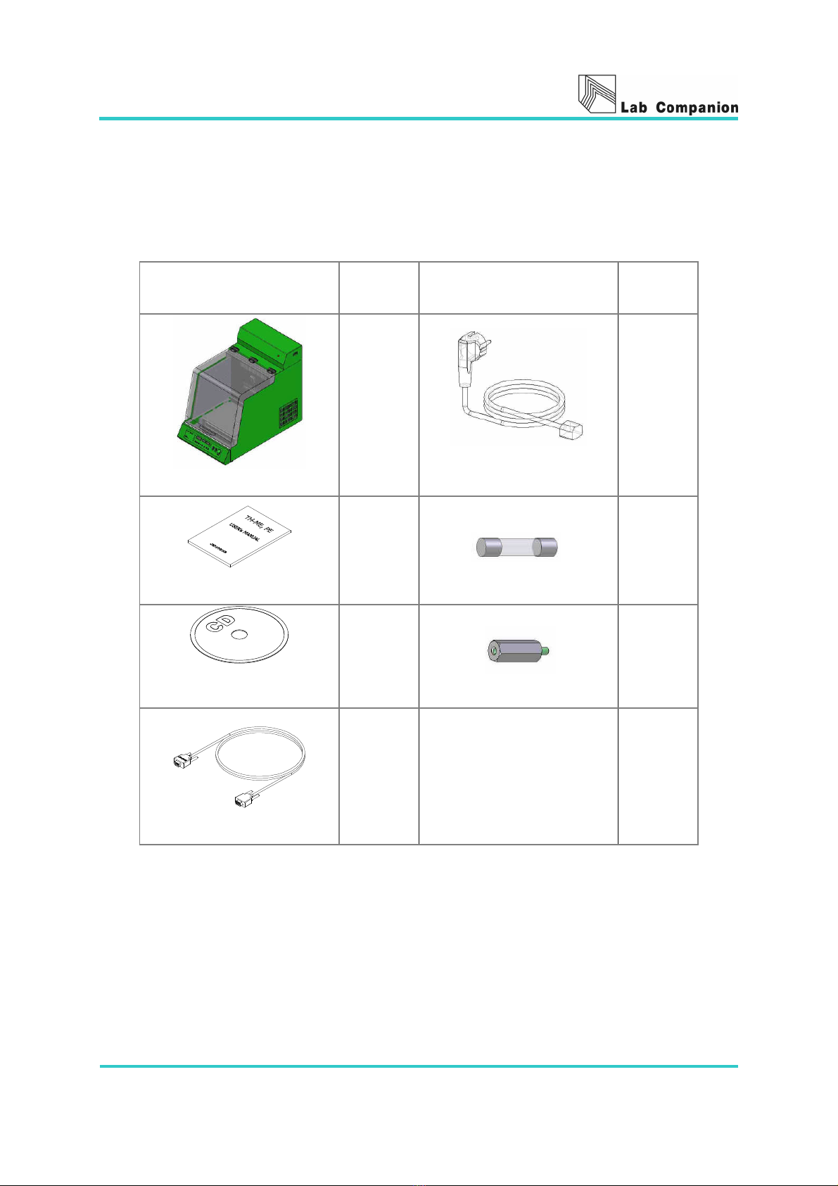
■Components of SI-300/300R/600/600R
After unpacking the unit, check the following components.
In addition, check the features and electric condition.
Components EA Components EA
unit
1
Power Cord
1
Operating instruction
1
Fuse
2
Software CD for
communication
1
Spacer
4
Cable for communication
1

Page 6
Table of Contents
◆ Introduction 2
◆ Confirmation of transport 4
OPERATING MANUAL
1. Warning for safe operation 7
2. Caution for safe operation 9
3. Safety alert definitions 10
4. System composition of SI-300R,600R 11
5. Introduction 13
6. Controller instruction 16
7. How to change the orbital motion and reciprocation motion 38
8. Accessories 39
9. Cause of malfunction and its repairs 46
10. Inspection cycle 49
11. Maintenance and cleaning 50
12. Specification 51
13. Warranty standard 52
14. How to waste 53
15. Warranty 54
16. Setting monitoring program 55
17. Operating monitoring program 56

Page 7
1. Warning for safe operation
Warning means that failure to follow this safety
statement could result in serious personal injury, or
death.
1. Please check the voltage, phase and capacity of power supply and connect properly.
☞ Abnormal connection causes fire or electronic shock.
☞ Power cord must be plugged into a wall outlet with grounded terminal.
2. Do not insert a lot of plug into the outlet at once.
☞ Using of unreasonable electronic power causes electric shock and fire.
☞ Must use a separate electronic wiring for the Temp & Humidity Chamber.
3. Power supply must be properly grounded.
☞ Abnormal grounded connection causes serious damage. Grounded connection must
not be on the water pipe and gas pipe.
4. Please check the power supply and frequency on the ID plate before installation.
☞ The unit requires an independent line (100V, 120V, 230V, single phase), a
grounded and polarized.
(100V, 120V:16AWG,12A,1.25SQ ; 230V:18AWG,10A,0.75SQ)
5. Do not install the product in the place that the gas could leak out.
6. Do not use in the place that has the industrial oil smoke and the metallic dust.
☞ It causes fire or electric shock.
7. Unplug, when there is strange sound, smell and smoke from the product.
☞ Please request the service.
☞ It causes fire or electric shock.
8. Keep out of the direct sunlight.
☞ It may cause fire and abnormal operation.
☞ When use in the direct sunlight, please set up a proper interception to make
shade.
9. Do not use in the place that has the industrial oil smoke and the metallic dust.
Keep in the dry place.
☞ It may cause fire and makes the product does not work well.
☞ Request service, if the product is flooded.
10. Do not assemble, repair, modify on your own.
☞ It may cause fire and electric shock.
☞ The product may not work well and fall off in the efficiency of the product.
☞ Please do not use with the exception of the origin purpose.

Page 8
11. Do not use or keep the inflammables near by the product.
☞ Inflammable gas or dust may cause fire.
☞ It may cause fire or explosion.
☞ Do not operate the product in a dangerous article area.
12. Never put inflammables and explosives in the product.
☞ A sample may explode in the chamber at a high temperature. The explosives are
acetic acid, ester, nitro compounds etc. and the inflammables are peroxides,
inorganic peroxides, acetate, and organic solvent.
☞ This product was not designed to prevent from any explosion.

Page 9
2. Caution for safe operation
Warning means that failure to follow this safety
statement could result in serious personal injury, or
death.
1. Do not pour water or put liquid on the top of the product when cleaning.
☞ It causes abnormal operation or trouble.
☞ Please intercept the main power immediately and request the service when water
may be in the product.
2. Do not let the product take any strong shock or vibration.
☞ It causes abnormal operation or trouble.
☞ It may deteriorate the ability of the product and not obtain correct results.
3. Do not put a heavy object on the main cord or let the cord be pressed down by the
product.
☞ It may take off the wire coating and causes the electric shock.
4. Do not touch it with wet hands and put the main plug correctly.
☞ Abnormal connection may cause fire,
☞ It may cause the electric shock or injuries.
5. Do not sprinkle insecticide or flammable spray on the product.
☞ It may cause trouble, the electric shock or fire.
6. Do not clean it with a strong cleanser (like solvent type) and use a soft cloth.
☞ It may cause fire or modification of the product.
☞ Clean it with a soft cloth dipping in neutral detergent.
Warnings and confirmations when operating the product
1. Insure a enough space because the cover is opened up to 70°.
2. Do not pull down the product and give a shock. Operate it on a flat place.
3. Please leave space between lighting fixtures (1.5m), wall (20cm) from the product.
4. Please maintain the horizontality of the product on a flat place to prevent
unusual vibration and sound.
5. Please set the product in a place which maintains the normal temperature and
humidity (less than 30°C, 80%RH), far from a heat source like a heater.
6. Please pay attention in transportation with propel equipment because it is heavy.
Confirmations after operating the product
1. Please check all wires have been operated accurately.
2. Please check the ground wire has been grounded accurately.
3. Please insure a enough space to operate.
4. Connect a hose to the Drain Hose Nipple. ( Refer to Page 18, #20)
5. After considering the safety regulations fully, use the product.

Page 10
3. Safety alert definitions
The safety alerts, attaching on the product, provide information of danger and safety
about it. All users must read this operating instruction carefully to operate the
product properly. The safety alerts should be attached in the same place below until
disusing the product. If the safety alerts are damaged, please request new labels to
an agent or us.
* Caution
It shows the caution when opening and shutting the inner
class door and the out door.
* Warning
It is to forbid putting inflammables and explosives
inside of the product.
* Caution
If the air filter is being stopped up, refrigeration
efficiency would be decreased and correct temperature
controlling would be impossible.

Page 11
4. System composition of SI-300R, 600R
CLS (Custom Logical Safe)-Control System
The CLS-Control system (Patent no.0328729) is our enhanced
safety controller developed by our engineers. Designed to allow
our equipment to be operated in environments that require
perfect thermal safety-including areas where flammable
chemicals are used.
In most cases with other brands of lab equipment, the CPU comprises both control and
safety features together. In the event of the CPU failing, the logic controlling the safety
features will often be compromised.
Jeio Tech has separated these two important elements and now has an independent
safety system running alongside the performance controller.
When any risk factors are sensed (ex: voltage peaks, short circuit, over temperature
etc.) the machine will go into a recoverable safety mode as follows.
The power supply to individual components is isolated by a magnetic switch,
leaving only the earth in circuit.
Details of the fault are displayed (indicator codes)
Audio and visual alarms are set off to alert the user and remain on until attended.
Shaking System
■ Stop the one regular position
The automatic system with Brake function allows the shakers can always stop at
the same position.
■ Turn Right and Left both ways
Our original Auto Reverse function allows it turns right and left both ways, in
addition to control the each turning time period by setting with the timer.
■ Speed recovery
The motor often check the set rpm and memorize the speed value. If there is
any outside interruption, it can recover the set speed.
■ Auto-control
To control speed and stop the one regular position accurately, it can memorize
the settle parameter value automatically.
■ Wide working range
From minimum 10 rpm to maximum 300 rpm, it works very stably.
■ Prompt acceleration and deceleration
It can accelerate/ decelerate promptly with the speed recovery function and the
brake function at once minimizing Over shoot/ Under shoot.

Page 12
Uniform temperature control
■ If the cover is opened, fan and heater will be stopped immediately to keep away
meeting inner air with outer air.
■ We use a cross type fan to make good uniformity.
Prevention against inner air leakage
■ To prevent against inner air leakage, external chamber is treated with heat
insulators and the open cover is stuck to the body unit with Packing.
■ To observe inside of chamber without opening the open cover, we are using a
translucent acrylic cover and setting a lamp up.
Programmed auto-run function
■ Our integrated controller allows controlling the inner circulating fan speed on
three steps. The 9-Step Programmed Control system can make to auto-run on
nine different temperatures and times (Max. 99hr. 59min.) and maximum 200
times for each time.
Safety device
■ Independent IC logic detects and intercepts electronic interference before the
main control board to give added safety to both user and product.
■ Built in Over Temp. protector warns (beep and LED lighted) and shuts off the
heater in the event of overheating problems.

Page 13
5. Introduction
(1) Cover
Easy to observe the sample through Acrylid.
(2) Over Temp. limit
This the safety device which is independent of the circuit.
The Heater reaches over the setting value, the controller shutdown of the
main power
Completely. the over temp. LED illuminates with audible Beep sound.
When the power is shut down, Please set the Knob over 15% than the setting
value.
Press the Start/Stop switch, and then Check the Temp LED illumination.
(3) Communication Port
The serial interface RS-232 can connect the PC through COM1 or COM2 port.
It’s allow to check the condition of the unit and the setting value.
This interface can restore the data and then print out.
(4) Body
※Back side
※ SI-300/600
※SI-300R/600R

Page 14
(5) Compressor Cover
The cover for the refrigeration System A/S.
(6) Foot
The foot for protected the unit from the dust..
(7) Shaking table
The shaking table relates to the shaking system. This can be installed the Universal
Platform, Spring wire wrack and other accessories.
(8) Main switch
Turn power on / off switch to unit
(9) Shaker I/O Switch
Turn On / Off switch to Shaker
(10) Lamp Switch
Turn on / Off for the inner chamber.
(11) Controller
- Shaking Control
Shaking Control can be set the left, right, pause function and each motion.
- Temp. Control
Temp Control has the Microprocessor(CPU) can be performed Digital PID Auto
tuning.
(12) Chamber Air Out
Inner air is out to go through the heater or Evaporator.
(13) Temperature Sensor
With Thin Film PT-100Ω
(14) Blower(Inner)
Blower for the temperature uniformity.
(15) Gas Spring
Gas spring is for changing the sample conveniently.
(16) Door Switch
There is door limit switch between door and the appliances mainframe upper parts,
and discontinuance gets operation of Shaking unit, Blower and Heater done by the
Logic IC which received an open signal if it opens Door. And Door LED is turned on.
(within five minutes)
Door LED twinkles for warning ventilation of a user after a door opened if a user does
not shut a door so that five minutes pass, and an alarm sound continuously rings.

Page 15
And it blocks off the power to be authorized with a power switch, and Off gets a
power switch done and all blocks off 2 phase of the power supplied with to an each
part of appliances, and configuration does the safe state that only a Ground part is
connected. At this time light is effective on Temp LED if closes a door again and
presses a Button.
(17) Lamp
Lamp is for observing the inside.
(18) Power Code
(19) Fuse
Fuse is for protecting the unit from the momentary overpower.
When exchanging the Fuse, check the main power.
Model Electric requirements Fuse Quantity Remarks
100V, 50/60Hz 2 EA
120V, 60Hz
AC 250V, 10A
Slow-blow 2 EA
SI-300/600
230V, 50Hz AC 250V, 5A
Slow-blow 2 EA
100V, 50/60Hz 2 EA
120V, 60Hz
AC 250V, 12A
Slow-blow 2 EA
SI-300R/600R
230V, 50Hz AC 250V, 8A
Slow-blow 2 EA
(20) Drain Hose Nipple
Drain hose nipple is for draining the moisture in evaporator.
(21) Filter
Filter by outboard is protecting the condenser from the dust.
(22) Hose Coupling(SI-300/600)
Circulating the heating medium in Evaporator when decreasing the inner temperature.

Page 16
6. Controller instruction
Planning for the shaking incubator
This controller is divided into the Temp LED and shaking LED.
Once setting the controller, the operator can use the Temp &
shaking function simultaneously.
Know well the operator to perform functions like temp, shaking,
programmed all on the controller in right process.
1. PV Display
Indicates the present value.
2. SV Display
Indicates the set value or remaining time
of the timer
3. rpm Display
Indicates the actual rpm or rotation
direction.
1 2 3 4
5 7 8 96

Page 17
4. Shaker LED
Shake LED
Illuminates When setting the time.
Flashes during the timer mode.
F/Ward
Illuminates when settting the clockwise
timer.
Flashes during the timer mode or anti
clockwise mode.
B/Ward
Illuminates when setting the anti clockwise
timer.
Flashes during the timer or clockwise timer
Pause LED
Illuminates when setting the pause timer.
Flashes
during the timer mode or pause mode.
5. Temperature LED
Temp LED
Set the temperature using of the TEMP Button,
Illuminates when pressing the START/STOP Button.
Heater LED
Indicates the heater output.
Auto-tune LED
Flahses during Auto-tune function.
Wait on timer LED
After setting time,indicates starting point
of the unit. Illuminates while operating.
Wait off timer LED
After setting time, indicates the unit
stops.Flashing the timer LED during
operation. The timer LED is lit, the timer
is standing by.
Door LED
When opening the door, shaking table,
heater,circulation fan stops operation.
After 5minutes, break the mainpower then
Door LED is flashing with audible Beep
sound.
Over temp. LED
When the inner temp is over the over temp.
limit, the unit stops then, flahsing the
Over temp LED with audible Beep sound.
Page 18
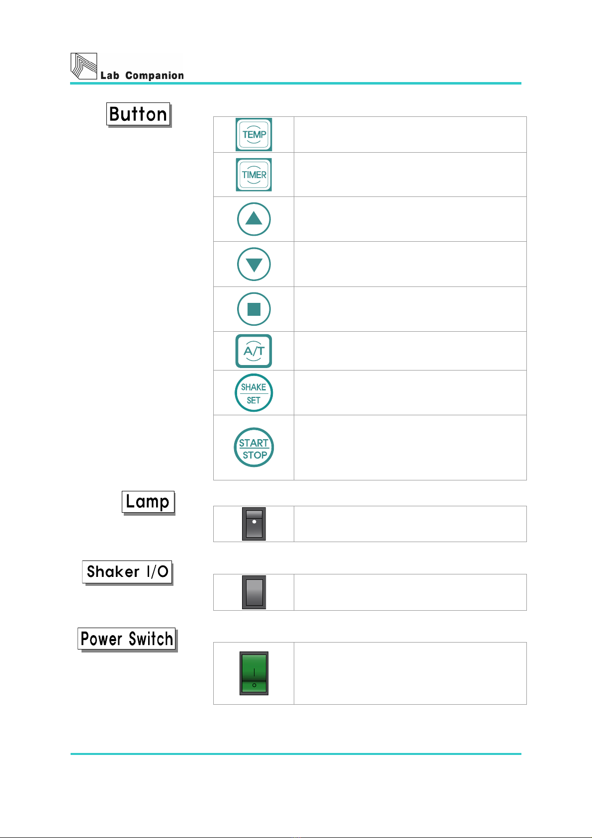
6. Entering button for the setting value
Temp Button
Setlects for the temp
Timer Button
Selects for the timer.
Up Button
Increases the set value.
Down Button
Decreases the set value.
Enter Button
After setting the value, store the set value
using of Enter button.
Auto-tune Button
Auto-tune Fu
nction operates while pressing
the button for a second.
SHAKE/SET Button
For Checkng the setting and present rpm
and entering the new rpm value
START/STOP Button
Starts and Stops the unit.
When the unit stops operating, user can
remove the beep sound and flashing LED with
Start/Stop Button.
7. Lamp Button
Turns On / Off the inner Lamp.
8. Shaker I/O Button
Shaker I/O Buton
Starts/ Stops the shaking table.
9. Power switch
Power switch
Turns On / Off the Power to shaker.

Page 19
The unit Operation
Before using the unit, Make sure the shaking direction to
protect the unit from the dust
Position the appropriate accessaries on the shaking
table and toghten securely.
If using the temp function, the unit should be operated
5minutes before.After maintaining the temp uniformity,
install the vessels and accessarries on the shaker table.
Select the desired value, Starts the operation
Control of the Temperature
This control is for the chamber of the inner temp.
Controlling the temp, other function and programming temp
using of the Temp button.
Method of the setting temp
① Turns on the power switch and wait for the unit
stabilized.
② Press Temp button.
③ Flashing the number activated on the SV display.
④ Set the desired temp with Up button and Down button
⑤ Press Enter button to finish setting.
⑥ After pressing the Start/Stop butoon, the unit operates
following the setting temp.
If not setting the temp for
10seconds, the display
will be back in the main.
This manual suits for next models
3
Table of contents
Other Jeio tech Laboratory Equipment manuals


Popular Laboratory Equipment manuals by other brands

Molecular Devices
Molecular Devices StakMax user guide

Sutter Instrument
Sutter Instrument MT-75 Series Assembly instructions

Bibby Sterilin
Bibby Sterilin Stuart SW5 Instructions for use

MMM Group
MMM Group ECOCELL 22 operating instructions

Specac
Specac Gateway ATR user manual

Faro
Faro SK07 Series instruction manual


Tuttnauer
Tuttnauer T-Top 10 Operation and maintenance manual

Endress+Hauser
Endress+Hauser Liquistation CSF48 operating instructions

Monmouth Scientific
Monmouth Scientific Circulaire HLFT1000 operating & maintenance manual

Bullard
Bullard Eclipse LD user manual

Elmi
Elmi CM-50M user manual

CURIOSIS
CURIOSIS Celloger Mini Plus Quick manual