CONTENTS
Page
l o
INTRODUCTION
·
.......
.
..................
.
.......................
1-
1
1 . 1
General
..................................•........•.......
1
-1
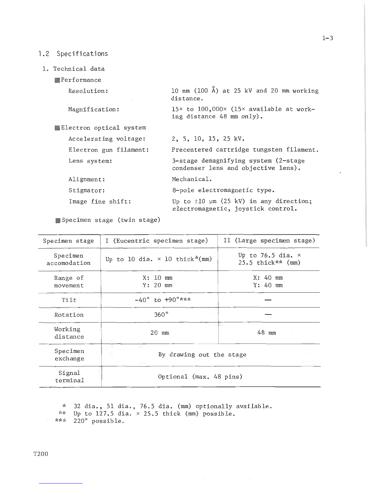
1. 2
Specifications
...................•..•....•....•...........
1
-3
1.
3
Layout
,
dimensio
ns
and
weight
...........•..••..........•..
1
-6
2.
DESCRIPTION
OF
MAIN
UN
IT
S
......................................
2-1
2.1
Column
and
specimen
s t a ge
•....................•.........•.
2-2
2 . 2
Display
panel
.....................................•.......
2- 3
2. 3
Checker
•....
..
.......
.
.....................••..•........
' .' 2- 5
2 . 4
Control
panel
···········
·
···················
. .
............
2-7
3.
OPERATION
·
..
....
.
..
..
..........................................
3
-1
· 3. 1
Startup
and
shutdo
wn
...................•......
.
..
.
........
3-1
3. 1 . 1
Star
t
up
'"
................•........................
3-1
3 . 1 . 2
Shutdown
····
···
·······
·
·················
·
··
·
·······
3-1
3.1
. 3
Power
failure
.........•............................
3
-1
3. 1 . 4
Water
failure
•...................
.
..........
...
....
3
-1
3.2
Specimen
mounting
. .
....
.
...................•..............
3
-2
3.
2.1
Specimen
preparation
....
.
...
.
.................•....
3-
2
3.
2.2
Eucentric
specimen
stage·
············
·
··
...
.
.......
3-
2
3. 2. 3
Large
specimen
stage
.
...
.
...
.
...........•......
. . . .
3-3
3. 3
Image
observation
....
.
.........................
.
..
.
......•
3-
5
3.3
. 1
Secondary
electron
image
(SEI)
. .
......
.
.......
.
....
3-
5
3.3
. 2
Backscattered
electron
image
(BEl)
. .
....•..........
3-7
3.3
. 3
Adjusting
the
rapid
ex
posure
marker
. .
..
...
..
..•.
. . ..
3-8
3.3.4
Astigmatism
correct
i
on
...
.
....
.
.....
..
. .
......
..
..
. 3- 9
3. 3. 5
Autom
a
tic
foc
us
mode
...............................
3-1
0
3. 4
FULL
AUTO
SEM
image
.....................
.
.........
.
•......
3-1
0
3. 5
Photograph
y··.··
......
.
.................•
.
..
.
...
.
...
.
.....
3-
11
3. 5
.1
Photographic
recording
sy
stems
.....................
3-1
1
3. 5
.2
Photog
r
aphing
the
sca
n
nin
g
image
....
.
...
. . .
........
3
-1
4
3. 5. 3
Film
speed
and
f-numb
er
..
......
.
....
.
..
.
...
.
..
.
....
3-
15
3. 5 . 4
Use
of
ultrahigh
speed
Polaroid
Land
sheet
film
(type
107
,
57
,
etc
.)
..
..
..
.
........
.
.............
. . 3-
15
3. 5 . 5
Data
readout
on
micr
ogr aph
.......
.
......
.
..........
3-1
6
3. 6
Aligning
the
mi
c
ros
c
op
e
......
.
...........
.
.....
. .
...
.
..
...
3-18
4.
MAINTENANCE
I
(General
Precautions)
......
.
.......
.
•.......
.
..
. . 4
-1
5.
MAINTENANCE
II (Parts
Replaceme
n
t)
. .
...........
.
.....
..
......
..
. 5
-1
5 . 1
Electron
gun
filament
r
eplacement
.................•.......
5-
1
5 . 2
Removing
the
condense
r l
ens
aper
t
ure
.........
..
...
.
......
. 5- 4
5 . 3
Removing
the
objective
lens
aperture
...
...................
5- 6
5.4
Disassembling
the
beam
deflecto
r . .
........
.
.........
.
..
. . .
5-8
5.5
Replacing
the
scintill
a
tor
........
.
..
..
..............
.
....
5- 9
5 . 6
Replacing
the
oil
diffusion
pump
heater
. .
..
..
.
........
.
...
5-
11
5 . 7
Oil
rotary
pump
maintenance
....
.
..
.
..
.
.........
.
...
...
. .
..
5-12
5.8
Fuse
replacement
....
.
...
. . .
.............
. . .
...
.
..
.
....
....
5-
13
7907001
01
T200