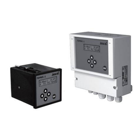
Jesco TOPAX DE User manual

TOPAX®DE
Two-Channel Controller
EN 01 Operating instructions
Read this operating manual before using the equipment.
To be retained for future reference.

2 | BA-40400-02-V14
Two-Channel Controller TOPAX DE
Table of Contents
1 Safety Instructions ............................................................................... 3
1.1 General ................................................................................................ 3
1.2 Identification of safety instructions in the operating manual ..................... 3
1.3 Personnel qualification and training........................................................ 3
1.4 Electrical device safety instructions ........................................................ 3
1.5 Hazards due to non-compliance with the safety instructions .................... 3
1.6 Working in a safety-conscious manner ................................................... 3
1.7 Safety instructions for the operator......................................................... 3
1.8 Safety instructions for installation, maintenance and inspection................ 4
1.9 Modifications and obtaining spare parts ................................................. 4
2 Before using the equipment................................................................. 4
2.1 Use for intended purpose....................................................................... 4
2.2 Scope of delivery .................................................................................. 4
2.3 Steps to take for start-up....................................................................... 4
3 Technical data....................................................................................... 5
3.1 Recommended cables........................................................................... 6
4 Assembly and Installation.................................................................... 7
4.1 General Notes....................................................................................... 7
4.2 Dimensions .......................................................................................... 7
4.3 Wall assembly....................................................................................... 7
4.4 Technical components ........................................................................... 8
4.5 Power connections................................................................................ 9
4.6 TOPAX on the EASYPRO water sampling station.................................... 10
4.7 Terminal clips of the main board and the technical components ............. 11
4.8 Input configuration .............................................................................. 13
4.9 Output configuration............................................................................ 14
4.10 Operation and keyboard layout........................................................... 17
4.11 First set-up and programming guidelines............................................ 17
4.12 Next steps ........................................................................................ 19
5 Measuring values inputs.................................................................... 19
5.1 Measurement input Disinfection (amperometric measurement cells)....... 20
5.2 pH value measurement input ............................................................... 21
5.3 Measurement output Redox potential .................................................. 23
5.4 Temperature measurement input.......................................................... 23
6 Explanation of digital signal inputs ................................................... 24
6.1 Start-up delay..................................................................................... 24
6.2 Deactivation of the controller function with alarm signaling in the case of lack
of sample water........................................................................................ 24
6.3 Low level alert, alarm and warning "level dosing pump" ........................ 24
7 Explanation of measuring values outputs ......................................... 24
7.1 General .............................................................................................. 24
7.2 Output types....................................................................................... 24
7.3 Output restriction ................................................................................ 25
7.4 Actuator ............................................................................................. 25
8 Controller explanation........................................................................ 25
8.1 Definitions .......................................................................................... 25
8.2 Proportional controller (P controller)...................................................... 25
8.3 Proportional-integral-derivative controller (PI, PID controller) .................. 25
8.4 Calculation of setable values................................................................ 26
8.5 Controller parameters.......................................................................... 27
8.6 Control direction ................................................................................. 27
8.7 Basic load dosing................................................................................ 27
8.8 Manual mode ..................................................................................... 27
9 Alarms................................................................................................. 27
9.1 Measurement alarms .......................................................................... 27
9.2 Safety cutout (Y alarm) ....................................................................... 27
10 Analogue power outputs 0/4…20 mA for remote displays .......... 28
11 Log book function............................................................................. 28
12 Menu configuration and main settings............................................ 29
12.1 Menu of TOPAX................................................................................. 29
13 Default settings ................................................................................ 37
14 Memory card..................................................................................... 37
15 Troubleshooting and diagnostics..................................................... 38
15.1 Self-setting alarms............................................................................ 38
15.2 Displays that must be confirmed with "OK"......................................... 38
15.3 Remedy............................................................................................ 38
16 terminal connection diagram for own configurations .................... 39
16.1 measurands .................................................................................... 39
16.2 Output types..................................................................................... 39
17 Device revision ................................................................................. 40
18 Warranty claim.................................................................................. 41
19 EC Declaration of Conformity........................................................... 42
20 Index ................................................................................................. 43

BA-40400-02-V14 | 3
Operating instructions
1 Safety Instructions
1.1 General
This manual contains essential information for the installation, start-up,
operation and maintenance of the equipment. Please have your staff and
any person in charge of the unit read and understand this manual be-
fore starting any work with it. Store this manual safely in a place where
mechanics, installers and other technical staff as well as operators can
rapidly access it in case of emergency. Attention must also be paid to all
the safety instructions in this manual.
1.2 Identification of safety instructions in the operating
manual
This operating manual contains essential safety instructions. Failure to
observe this information may endanger other people and the unit. The
safety instructions are identified by the following symbols:
WARNING!
Refers to a potentially hazardous situation. Failure to follow
this instruction may lead to death or severe injury.
CAUTION!
Refers to a potentially hazardous situation. Failure to fol-
low this instruction may lead to minor injury or damage
to property.
ATTENTION! or NOTICE!
Failure to comply with this safety instruction may result in
damage to the device and endanger its operation.
IMPORTANT!
This refers to additional information to facilitate operation
and ensure the smooth running of the equipment. Appropri-
ate reference attached directly on the unit or any of its other
parts must absolutely be considered and held in completely
readable condition for future reference.
1.3 Personnel qualification and training
Your installation, operation, maintenance and inspection staff must be
trained and qualified for these tasks. Personnel areas of responsibility,
tasks and supervision must be controlled and ensured by the operat-
ing company at all times. Unskilled personnel must be trained and in-
structed. If necessary, this can also be performed by the manufacturer
or certified supplier on behalf of the operating company. The operating
company must also ensure that the operating manual has been under-
stood.
1.4 Electrical device safety instructions
Basic safety precautions should always be followed when installing and
using this electrical equipment. These include the following:
WARNING!
1.) Read and follow all instructions.
2.) To reduce the risk of injury, do not permit children
to use this product unless they are closely super-
vised at all times.
3.) Risk of electric shock. Ensure that the device is
secured with a ground fault - circuit breaker (GFCI
= earth-leakage circuit breaker). Contact a qualified
electrician if you cannot verify whether the connec-
tion is protected by a GFCI.
4.) Do not bury cord. Fix the cable to minimise pos-
sible damage due to lawn mowers, hedge trimmers,
and other equipment.
5.) To reduce the risk of electric shock, replace the
cable immediately if damaged.
6.) To reduce the risk of electric shock, do not use an
extension cable to connect the device to the power
supply; use an appropriately located socket.
7.) Keep these instructions for future reference.
1.5 Hazards due to non-compliance with the safety
instructions
Failure to comply with the safety instructions may endanger not only
people, but also the environment and the unit. Failure to follow the safety
instructions will invalidate any damage claims.
The following hazards in particular may arise: Failure of major func-
tions of the device. - Danger to persons from electrical, mechanical and
chemical influences. Danger to the environment due to leakage of haz-
ardous substances.
1.6 Working in a safety-conscious manner
The safety instructions contained in this operating manual must be ob-
served. The operating company is responsible for ensuring compliance
with local safety regulations. Any faults that could affect safety must be
rectified immediately.
1.7 Safety instructions for the operator
Statutory regulations must be observed. Consumables and replacement
parts must be disposed of safely and in an environmentally friendly man-
ner. Avoid possible hazards from electric current (for further details refer
to section 1.4).

4 | BA-40400-02-V14
Two-Channel Controller TOPAX DE
1.8 Safety instructions for installation, maintenance and
inspection
The operating company must ensure that all installation, maintenance
and inspection work is carried out by qualified and authorised personnel.
WARNING!
Installation and maintenance work on the equip-
ment must only be carried out after the de-
vice has been disconnected from the power
supply. The device must be prevented from
being switched on again during the above work.
Auxiliary modules should be fitted/removed in this
condition. Cables should also only be attached in this
condition.
ATTENTION!
Before opening the device, ensure that it cannot suf-
fer damage through electrostatic discharge. The fit-
ter is to perform all necessary measures to this end
(e.g. touch a metal conductor which is grounded).
Use ESD-compliant, conducting tools when chang-
ing electronics components and connecting the ca-
ble. Wherever possible, avoid contact with electronic
components with bare hands or uninsulated tools.
Neglecting of these instructions can lead to severe damages of
TOPAX and loss of warranty.
All safety mechanisms and guards must be refitted and reactivated as
soon as the work is completed.
ATTENTION!
As well as faulty installation, incorrect controller set-
tings (setpoint, parameter and configuration level
data, and device-internal modifications) can impair
the process or result in damage.
There should always be a safety device independent of the controller.
Configurations may only be carried out by technical personnel! If neces-
sary use password protection. Always comply with the safety regulations
of the country of use.
1.9 Modifications and obtaining spare parts
TOPAX may be converted or changed only by qualified technical person-
nel.
If the configuration of the TOPAX is wrongly made by assembly or ser-
vice personnel, errors and dangers in the function of the machine can
result. In this case, the manufacturer declines any liability.
ATTENTION!
Only genuine manufacturer spare parts and sensors
may be used. Failure to comply will invalidate the
warranty.
2 Before using the equipment
2.1 Use for intended purpose
The TOPAX is exclusively designed and meant for metering and control
applications in water treatment plants and waste water management.
The operational safety of the unit can only be ensured if used according
to its purpose.
All other types of use are prohibited and will invalidate the warranty.
2.2 Scope of delivery
Carefully check the delivery prior to installation and refer to the delivery
note to ensure the delivery is complete and to check for any transport
damage. Contact the supplier and/or carrier regarding any questions
concerning the delivery and/or transport damage.
Do not operate defective devices.
The scope of delivery includes:
• TOPAX casing (as per the model)
• Tool (M4 screw) to open the casing
• Memory card
• Mounting material
• Operating instructions
• Measuring protocol
• Terminal plan for the sensors
• Electrodes (optional)
• Cable connection TOPAX to the electrodes (optional)
The device is delivered either as detached or mounted onto a measuring
water table.
2.3 Steps to take for start-up
The following steps are recommended by the manufacturer in order to
install the TOPAX successfully:
• Reading the operating instructions
• Installing the device
• Attach the sensors and actuating element (to the controlling
pumps and switch, etc.)
• Calibrate the sensors to the measuring output
• Adjusting the input measuring ranges
• Controller explanation
• Configuration of the regulating output

BA-40400-02-V14 | 5
Operating instructions
3 Technical data
Supply voltage 90 … 264 V AC, 47 … 63 Hz
Power consumption Approx. 24 W
Housing dimensions 302 x 231 x 108mm (W x H x D) wall-mounted housing
Display Graphic colour display 5.7 inch, 320 * 240 pixels (RGB), with LED backlight (lighting dims automatically after 10 minutes)
Keyboard Keyboard with touch keys
Measurement inputs
(potential-free)
Inputs for disinfection, pH value, REDOX potential, temperature
Control characteristic for 2 inputs
(disinfection, pH value)
P, PI, PD or PID performances
Fixed value regulation, standard channel selectable with disturbance variable feed forward
2-side controller
Control parameters Xp: 1…500%, Tn: 1…200 minutes, Tv: 1...1200 seconds
Measurement input Disinfection Open amperimetric electrode with mechanical cleaning (excess chlorine detector with 2 electrodes, CS 120)
Measuring range adjustable from: 0-1,00 mg/l, 0-2,00 mg/l, 0-5,00 mg/l oder 0-10,00 mg/l. Connection via series terminals*
Potentiostat (PM)
Measuring range adjustable from: 0-1,00 mg/l or 0-2,00 mg/l
Encapsulated electrode 20 mA type with supply of the measuring cell (24 VDC), measuring range depending on
measuring cells
Measuring range adjustable from:
0 – 1,00 mg/l, 0 – 2,00 mg/l or 0 – 10,00 mg/l
Measuring input for pH value Measuring range pH 0 … 14 Connection via series terminals*
REDOX potential measuring input
(for disinfection)
Measuring range
0...1000mV
Connection via series terminals*
Temperature measuring input - Pt
100
Measuring range
-10°C…+100°C
Two-leader connection by means of line-up terminals*
Total chlorine measuring input Encapsulated electrode Measuring range adjustable from:
0 – -1,00 mg/l, 0 – 2,00 mg/l or 0 – 10 mg/l
Disturbance variable input (option-
ally available)
0...20 mA or 4...20 mA
Disturbance factor: 0.1 … 10 times amplification
Digital inputs - Low level alert input for metering pump 1
- Alarm level input for metering pump 1
- Low level alert input for metering pump 2
- Alarm level input for metering pump 2
- Measuring water shortage disconnection of the regulating function with alarm (external switch off)
Controller outputs Electronic output
(optocouplers)
- 48 V DC; 250 mA
(Pulse frequency 10 … 350 Impulses/min)
Relay output - ON/OFF
- Pulse frequency 10 … 100 Impulses/min
- Pulse length 10 … 3600 seconds
- 3-point step output with
- Position feedback
value of the Potentiometer 1 … 10 kOhm
Continuous output 0/4…20 mA, max. load 500 ohms
Alarm output Relay output as collective alarm for the measuring size of Disinfection, pH value, redox potential, temperature and conductivity as
potential free changer
Measurement alarm Min. and max. alarm freely adjustable, time delay adjustable: max. 200 min
Safety cutout To prevent over metering (Y-alarm), time delay adjustable: max. 200 minutes
Current outputs for remote trans-
mission of measuring values
- Disinfection
- pH value
- Redox potential
- Temperature
0/4 … 20 mA possible spreading; max. load 500 ohms potential free
Useful spreading >50% with measuring input Disinfection and 0/4...20mA
>10% during measurement input of pH-value and redox potential
Computer interface (optional) RS 485
Load capacity of the relay 230VAC, 3A
Protection class IP65 with locked screw connections
Ambient temperature -5°C … +45°C
Air humidity 95% non-condensing
*) max. 0.5mm² with cable end sleeve and max. 1.0mm² without cable end sleeve.

6 | BA-40400-02-V14
Two-Channel Controller TOPAX DE
3.1 Recommended cables
Recommended cables for the different connections and applications:
Connections and applications Dimensions Types
Mains voltage M20 X 1.5 NYM-I 3 x 1.5 mm (9.1 mm)
Relay output (ATE- engine) M20 X 1.5 NYM-I 4 x 1.5 mm (9.8 mm)
Relay output (pulse frequency), (pulse length) M16 X 1.5 NYM- O 2x 1.5 mm ( 8.7 mm)
Relay output alarm) M16 X 1.5 NYM- O 3x 1.5 mm ( 9.1 mm)
connection to PC, computer cable Cat 5 M12 X 1.5 Type 2X2XAWG24/1 ( 5.7 mm)
Connection of current outputs (remote communication cable) M12 X 1.5 J-Y (St) Y 4 x2x0,6 mm ( 6.5 mm)
Position feedback ATE- engine (remote communication cable) M12 X 1.5 J-Y (St) Y 2x2x0.6 mm ( 5.0 mm)
Continuous controller output (remote communication cable) M12 X 1.5 J-Y (St) Y 2x2x0.6 mm ( 5.0 mm)
Input measuring cell M12 X 1.5 LIYY 2x 0.25 mm
Digital inputs (for each input) (remote communication cable) M12 X 1.5 J-Y (St) Y 2x2x0.6 mm ( 5.0 mm)

BA-40400-02-V14 | 7
Operating instructions
4 Assembly and Installation
4.1 General Notes
For installation, the local directions and regulations have to be adhered
to. Any mounting position is possible. The ambient conditions are to be
maintained in accordance with the technical data. Exposure of the unit
to direct heat and sunlight must be avoided.
4.1.1 Diagram TOPAX housing
The TOPAX device is composed of two parts, a rear and a front housing.
The rear shell of the housing is electrically connected with a flat cable
with the front one.
The front housing aand the rear housing bof the controller are fitted
together with two pivots (cand d). The unit is designed so that the
controller can be opened from either side.
db
c
a
⑤
f
aFront housing
bRear housing
cHinge pivot (fitted)
dHinge pivot (disassembled)
⑤Pivot head (unscrewed)
fPivot disassembly tool
4.1.2 Opening the housing
To open the housing it is preferable to remove the right pivot. To do this,
unscrew head ⑤of the pivot. The pivot disassembly tool fserves the
purpose.
ATTENTION!
In order to open the housing remove only one pivot
from the equipment. If both pivots are removed at
the same time, the front housing will no longer be
attached to the bottom section.
ATTENTION!
The equipment must only be opened when it is dis-
connected from the power supply.
4.2 Dimensions
Fig.1: Dimensions TOPAX
4.3 Wall assembly
For the wall assembly 4 mounting holes are to be found in the lower part
of the housing. The hardware for wall fixation is provided with the unit
by the manufacturer.
171 mm
267 mm
Fig.2: Spacing of hole for mounting the device
4.3.1 Rear housing
consists of rear housing with the motherboard, in which the cable con-
nections are screwed in.
On the motherboard there are the main modules for the functioning.
Depending upon the model, two input assemblies are available together
with one output assembly. For networking purposes with connection to
a PC, an additional interface (RS485) is available. All assemblies are at-
tached to the main board by plug connectors and fastened with several
nuts.
4.3.2 Front housing
The front housing contains the display board and the keyboard. A colour
display is included to show measurements and allow for adjustment. The
operation takes place with 6 function keys as well as a control cross with
"OK" key. The keys are integrated in a keyboard and react to contact. All
displays of the individual menus appear as plain text.
302 mm
240 mm

8 | BA-40400-02-V14
Two-Channel Controller TOPAX DE
4.4 Technical components
Besides the main board, the following can be fitted in addition
• up to 2 input components
• an output component and
• an Interface module (RS 485)
To operate the TOPAX at least one entry component has to be built in.
output block
mainboard
DO4 DO3 DO2 DO1
DO7 DO6 DO5
DO0
PC interface RS 485
+-
+-+-+-+-+-+-+-
1
2
3
4
5
6
7
8
9
10
11
12
13
14
15
16
17
18
19
20
21
22
23
24
25
26
27
28
29
30
31
32
20 mA Power Outputs Digital Outputs
36
37
38
PE
N
L
power generator
33
34
92
93
94
87
88
89
90
91
86
-+
81
82
83
84
85
- -+ +
56
57
58
59
60
-+
51A
52A
53
54
55
61
51B
52B
- -+ +
-
+
71
72
73
74
75
76
77
78
5-fold input block
Alarm relays
39
40
41
43
44
45
46
42
35
95
96
B
A
3-fold
input block
Plugin connector
to the display circuit board
Fig.3: Arranging the components on the main board
4.4.1 Main board
Besides this function, to incorporate the further components, the main
board is made up of the following connections:
• 5 analogue power inputs (0/4 … 20mA)
• 5 digital inputs
• Alarm relay
• power supply
4.4.2 5-fold Input block
with 5 measurement inputs for:
• Dinsinfection (single amperimetric electrode or encapsulated
electrode) (0/4...20 mA)
• pH single-rod measuring cell
• Redox single-rod measuring cell
• Temperature sensor Pt100
• Position feedback of a servo motor with potentiometer
4.4.3 3-fold Input block
with 3 measurement inputs for:
• Disinfection (potentiostatic measuring cell)
• Position feedback of a servo motor with potentiometer
• 0/4 20 mA power entrance for the connection of a disturbance
variable
4.4.4 Output board
On the output block there are 5 integrated relay output and 3 electronic
outputs (optocouplers).
The following output can be configured:
• Control output Disinfection
with various output functions
• Control output pH-value
with various output functions
The software configuration automatically assigns these outputs to the
respective terminals in a sequential order- depending on the configura-
tion of the TOPAX:
1. Disinfection controller
2. Controller pH value
Depending upon output type, TOPAX selects the next free relay output or
optocoupler. The clamps are assigned in a firm order: clamps 87/88 to
95/96 for relays, or 81/82 bis 85/86 for optocouplers.
NOTE!
For further information on the terminal connection,
refer to section “4.7 Terminal clips of the main board
and the technical components” on page 11.
4.4.5 Interface board RS 485
The TOPAX has the option of being fitted with a serial interface RS 485.
The RS 485 allows you to transfer data to a PC. The MODBUS protocol
serves as data transmission protocol.
With the RS 485 interface it is possible to connect more than one TOPAX
to a network. For this an address is to be assigned to each TOPAX. In
addition to this each TOPAX is fitted with a computer-interface RS 485.
It is possible to have a maximum of 1000 m of data transfer with the
RS 485 interface. Up to 14 TOPAXs can be connected to a network with
a PC.
ATTENTION!
The data line is to be attached direct to the con-
necting terminals of the TOPAX (clip A and B, see
Fig.4). Separate external connection or distribution
boxes must not be set. The network address 10 is
not permitted.
IMPORTANT!
For the realization of a network with the TOPAX and
the structure of a bus system to a PC a computer
cable "KAT.5 type 2X2XAWG24/1 (Lapp cable)" or
better is to be used. Using other cables can cause
data errors and affect the data transmission. The
manufacturer is not liable for this.
Most modern computers are equipped with the serial computer interface
R-S 232 and/or with USB - interfaces. For the connection to a RS 485
network, an additional connector converter (RS 485 to RS 232 or RS
485 to USB) is necessary.
There are interface components in the under casing part of the main
board in the TOPAX. It is partially hidden from view by the output module.

BA-40400-02-V14 | 9
Operating instructions
Fig.4: RS 485 connections on the interface module board, partially obscured by
the output module
CAUTION!
The data line must be locked at both sides with a
120 Ohm line resistance and must be supplied a
firm potential using the two link plugs on the two
jumpers on the circuit board of the display of all la-
test TOPAX versions.
Two link plugs/jumpers have to be connected to the TOPAX (the last one
in the network) for the 120 ohm switch, Pull-up and Pull-down resist-
ances. The resistances are not active when the system is delivered. The
resistance of 120 ohms on the PC side is applied via the connector
converter.
The jumper slots are located in the front of the housing on the display
board, above the flat band-connection to the main board.
Resistors deactivated
(delivery status)
Resistors activated
(last device in the network)
Jumper position: OFF Jumper position: ON
The resistors are NOT active.
The jumpers are set DOWN
The resistors are activated.
The jumpers are set UP
Fig.5: Position and setting of the jumper to activate the RS 485 resistances on
the last TOPAX in the network.
4.4.6 TopView software
For remote viewing on a PC the manufacturer offers the full version of
the TopView display program and a freeware version with limited func-
tionality. The "TopView mini" freeware version is free on the internet and
can be downloaded from the manufacturer's website.
4.5 Power connections
The equipment may be installed and attached only by authorized and
qualified electricians. Connections must be made according to the en-
closed wiring diagrams.
ATTENTION!
Only work on electrical connections while the device
is disconnected from the power supply.
Insert the cables in the various connections screwed on the bottom side
of the housing. After the installation, tighten all cable connections so
that the required protection class is provided.
Fig.6: Cable connections for protected cable passage to the rear part of the
housing.
For the connection to the power supply and to the actuators, TOPAX is
equipped with special terminal clips.
Fig.7: The principle of the connecting terminal to the technical components.
For a better assembly these clamps are designed plug-ins, whereby the
maximum cross section is 2.5 mm2for the power cord and 1.5 mm2for
all other cable to the terminal clips.

10 | BA-40400-02-V14
Two-Channel Controller TOPAX DE
Fig.8: Individual connecting terminals, removable for installation, of the technical
components.
ATTENTION!
When choosing the line material, for installation and
electrical connection of the device, observe the regu-
lations of VDE 0100 “Provisions for setting up elec-
tric power plants with nominal voltages below 1000
V“ or the individual national rules.
ATTENTION!
The equipment is not suitable for the installation in
explosive conditions!
4.5.1 Connection of the in- and outputs
NOTICE!
Terminal clips allocation depends on the software
configuration of TOPAX. Terminal clips allocation de-
pends on the delivered equipment.
The delivered equipment is listed in the protocol, which is attached to
the device. Use this terminal plan to wire the device and to put it in
operation.
4.5.2 Voltage supply
This instrument has no power switch and is immediately operative after
the creation of the operating voltage. For this reason an external switch
and/or protective switch is to be planned.
For the connection to the power supply at the main board, refer to the
enclosed terminal plan (see “4.7 Terminal clips of the main board and
the technical components” on page 11).
ATTENTION!
DO NOT let power be switched on via timer opera-
tion!
4.5.3 Sensor technology
Measuring cables may not be parallel when too close (less than 15 cm)
to power switches and/or cables for power installation. Separate cable
channels are to be used. Disturbing stray effects could otherwise falsify
the measurement. Power supply and measuring lines at close proximity
should only cross at a 90° angle.
The maximum permissible length of the measuring cables depends on
the kind of the sensor. When performing very ohmic measurements (e.g.
pH or REDOX measurements) the following is to be considered:
• Connections and patch cords must be clean and dry.
• The permissible bending radius of the cable must be respected.
• The quality of the holding wires must correspond to the defaults
from the data sheet of the sensor.
IMPORTANT!
If possible a continuous cable is to be used from the
sensor to the measuring entrance. An extension of
the cable by plugs or terminal socket increases the
risk of disturbances due to contamination, humidity
or excessive transition resistances.
4.5.4 Connecting the actuators
When connecting your actuator the equipment must be switched off to
prevent uncontrolled starting and malfunctioning.
WARNING!
If devices e.g. dosing pumps with inductive loads
from a nominal current of 1 A are connected to
a relay, the contacts in the relay may be bonded.
Thus, the device will operate in an uncontrolled
manner. This may also result in an overdosing of
chemicals. To prevent the output relays from bond-
ing if the load circuit shorts, they must be protected
separately on the maximum relay switching current.
For inductive loads, protective circuit must be ap-
plied to the relay contacts (spark suppression). The
manufacturer recommends the use of the interfer-
ence suppression module / spark suppression de-
vice (article 78614).
4.5.5 Replacing the batteries
The life of the batteries (Type VARTA, CR1/2 AA, 2 Volt, Lithium) provided
with the internal instrument clock is approx. 5 – 10 years. When the bat-
teries wear out causing a power shortage, a warn-ing message will be
displayed on the instrument. The battery is welded on the display circuit
board. It must be replaced by a skilled technician.
Fig.9: Battery for internal clock, on the display circuit board.
4.6 TOPAX on the EASYPRO water sampling station
If the TOPAX is set up on an EASYPRO water sampling station, it controls
the illumination of the LEDs. The LEDs of the sensors are controlled via
the measured values. The LEDs illuminate green when the measured
values lie within the set range. Leaving these ranges causes the LEDs
to illuminate red.
TThe DIN contact must be activated in the control.

BA-40400-02-V14 | 11
Operating instructions
4.7 Terminal clips of the main board and the technical
components
output block
mainboard
DO4 DO3 DO2 DO1
DO7 DO6 DO5
DO0
+-
+-
+-+-+-+-+-+-
1
2
3
4
5
6
7
8
9
10
11
12
13
14
15
16
17
18
19
20
21
22
23
24
25
26
27
28
29
30
31
32
20 mA Power Outputs Digital Outputs
36
37
38
PE
N
L
power generator
33
34
92
93
94
87
88
89
90
91
86
-+
81
82
83
84
85
- -+ +
56
57
58
59
60
-+
51A
52A
53
54
55
61
51B
52B
- -+ +
-
+
71
72
73
74
75
76
77
78
5-fold input block
Alarm relays
39
40
41
43
44
45
46
42
35
95
96
B
A
3-fold
input block
Plugin connector
to the display circuit board
Fig.10: Rear part of the housing with the main board, the input module 5-fold,
the input module 3-fold, the output module and the partly hidden PC interface.
4.7.1 Main board
Terminal Function
Analogue power outputs 0/4...20 mA (also see chapter 11)
1 + Measurement output
0/4...20mA
Disinfection
2 -
3 + Measurement output
0/4...20mA
pH value
4 -
5 + Measurement output
0/4...20mA
Redox
6 -
7 + Measurement output
0/4...20mA
Temperature or programmed as
controller output
8 -
9 + Measurement output
0/4...20mA
combined chlorine or programmed
as controller output
10 -
11 + Measurement output
0/4...20mA
conductivity or programmed as
controller output
12 -
13 + Continuous control
output
0/4...20mA
programmed as controller output
14 -
15 + Continuous control
output
0/4...20mA
programmed as controller output
16 -
ATTENTION!
The constant regulating outputs 0/40 ... 20 mA of
the main board are also allocated automatically in
the software configuration as per a fixed rank order
of the terminals, in accordance with the allocation
procedure for the output components.
Ranking of the outputs for automatic allocation:
1. Control output Disinfection
2. Control output pH value
3. Controller output for combined chlorine
4. Controller output for conductivity
5. Flocculation pump output
In the same way the clamps are assigned in a firm order.
• Terminals 15/16
• Terminals 13/14
• Terminals 11/12
• Terminals 9/10
• Terminals 7/8
The clip allocation is automatically displayed at the end of the configura-
tion.

12 | BA-40400-02-V14
Two-Channel Controller TOPAX DE
Terminal Function
Digital inputs
17 potential free input measuring water shortage *)
18
19 potential free input filter cleaning *)
20
21 potential free input low level alert Controller 1 **)
22
23 potential free input level alarm Controller 1 **)
24
25 potential free input low level alert Controller 2 **)
26
27 potential free input level alarm Controller 2 **)
28
29 potential free input activate night mode operation
30
31 potential free input not used
32
*) normally ON or normally OFF
**) normally ON or normally OFF or not active
33 A internal
PC interface
interface for software updates
34 B
35 GND
36 alarm relay as common
alarm
Opener
37 middle contact
38 Closer
39 PE protective conductor Voltage: 90 up to 264 V AC
40 PE
41 N neutral conductor
42 N
43 N
44 L phase
45 L
46 L
4.7.2 Input module (5x)
Terminal Function Cable colour Comment
51A + Disinfection
(amperometric
measuring cell type
CS 120)
Electrode mating
copper/platinum
or silver/platinum
possible
CS 120 (Cu/Pt)
Cu/ : blue (-)
Pt/ : red (+)
CS 120 (Ag/Pt)
Ag/ : purple(-)
Pt/ : red (+)
variant A and
variant B can be
only used as an
alternative
52A -
51B + - total chlorine measuring cell
(4...20mA)
- membrane covered cell
Disinfection (0/4...20 mA)
(20 mA input with 24 V DC sensor
power)
52B -
53 + pH value
54 -
55 + Redox
56 -
57 Temperature
(polarity at wish)
58
59 potentiometer with positional feedback for servo motor
(polarity of clips 59 and 61 at wish)
60 Driver
61
4.7.3 Input module (3x)
Terminal Function Cable colour
71 Reference electrode
(with integrated cable)
Disinfection
(potentiostatic
measuring
cell)
Reference electrode
(Glass): black
Counter electrode (Stain-
less steel): red
Measuring electrode (gold):
purple
72 Counter electrode
Stainless steel
73 Measuring electrode
(gold)
74 + 20 mA passive (no supply to the sensor)
- conductivity measurement or disturbance
variable
75 -
76 Potentiometer with positional feedback for
Servo motor. (polarity of clips 76 and 78
at wish)
77 Driver
78
4.7.4 Output module
Termi-
nal
Output
81 + Electronic output (DO7) (Optocoupler) configurable
82 -
83 + Electronic output (DO6) (Optocoupler) configurable
84 -
85 not available
86
87 Relay output (DO 4) configurable
88
89 Relay output (DO 3) configurable
90
91 Relay output (DO 2) configurable
92
93 Relay output (DO 1) configurable
94
95 Relay output (DO 0) configurable
96
ATTENTION!
The constant regulating outputs 0/40-20 mA of the
output components are also allocated automatically
in the software configuration as per a fixed rank or-
der of the terminals, in accordance with the alloca-
tion procedure for the main board.
The outputs are allocated according to ranking:
1. Disinfection controller
2. Controller pH value
3. Controller combined chlorine
4. Controller conductivity
5. DIN contact
6. Eco-contact
7. Flocculation contact
Depending upon output type, chloriDES selects the next free relay output
or optocoupler. The clamps are assigned in a firm order: clamps 87/88
to 95/96 for relays, or 81/82 to 83/84 for optocouplers.

BA-40400-02-V14 | 13
Operating instructions
4.8 Input configuration
No. Article name Function Terminal
1 Conductivity Transmitter and Measuring Cell 20/60 mS/cm Conductivity 74 + 75
2 Diaphragm-covered Measuring Cell Type CD 4 MA Chlorine dioxide 51B + 52B
3 Diaphragm-covered Sensor 4...20 mA Type Cl 4.1 A 2 Free chlorine 51B + 52B
4 Disturbance variable 4-20 mA Disturbance variable* 74 + 75
5 Measuring Cell for Total Chlorine Total chlorine 51B + 52B
6 Measuring Electrode for Disinfection Measuring, Reference Electrode for Disinfection Measuring Free chlorine 71 + 72 + 73
7 pH Single-Rod Measuring Cell PE110 pH 52 + 53
8 Redox Single-Rod Measuring Cell ME110 ORP 54 + 55
9 Reference Electrode for Potentiostat; SS Electrode for Potentiostat 1.4571; Gold Electrode for Potentiostat Free chlorine 71 + 72 + 73
10 Residual Chlorine Measuring Cell CS120 Free chlorine 51A + 52A
11 Resistance Thermometer TE 110, PT100 Temperatur 56 + 57
Overview
56
57
58
59
60
-+
51A
52A
53
54
55
61
51B
52B
- -+ +
-
+
71
72
73
74
75
76
77
78
Sliding contact
Measuring Cell for Total Chlorine (Pos. 5),
4...20 mA Typ Cl 4.1 A 2 (Pos. 3)
or
CD 4 MA (Pos. 2)
CS 120 (Pos. 10)
+ = red
- = blue/violet
PE 110 (Pos. 7)
ME 110 (Pos. 8)
TE 110, PT 100 (Pos. 11)
Disinfection (Pos. 6)
or
Potentiostat (Pos. 9)
Conductivity (Pos. 1)
or
Disturbance variable 4...20 mA (Pos. 4)
Feedback
servomotor
Feedback
servomotor

14 | BA-40400-02-V14
Two-Channel Controller TOPAX DE
4.9 Output configuration
No. Article name Output Configuration Signal type Terminal
1 C7700 20mA Current output Current output (20mA) analogue
See TOPAX menu configuration 0.6.3
2 C7700 3-p-s Relay (3 step) 3 point step with poti digital
3 EASYZON D/Da Current output Current output (20mA) analogue
4 MAGDOS DE, DX, LT, LDp, LD, LK, LP Opto coupler output Impulsefrequency (opto) digital
5 MAGDOS LA, LP, DX Current output Current output (20mA) analogue
6 MAGDOS LB bis 2018 Relay (with power relay*) On/off digital
7 MAGDOS LDp, LD, LK, LP, LB ab 2018 Relay On/off digital
8 MEMDOS DX, LA, LP Current output Current output (20mA) analogue
9 MEMDOS DX, LP Opto coupler output Impulsefrequency (opto) digital
10 MEMDOS E, LB Relay (with motor protection*) On/off digital
11 MEMDOS SMART LB, LD, LK, LP Relaisausgang On/off digital
12 MEMDOS SMART LD, LK, LP Opto coupler output Impulsefrequency (opto) digital
13 MEMDOS SMART LP Current output Current output (20mA) analogue
14 MIDIDOS E Relay (with motor protection*) On/off digital
15 MINIDOS A Relay (with motor protection*) On/off digital
16 Peristaltic pump Relay (with motor protection*) Impulselength (relais) digital
17 Technoline SC Relay Impulselength (relais), min. 300s digital
18 Technoline SC Relay On/off digital
19 Technomat PS Relay Impulselength (relais), min. 300s digital
20 Technomat PS Relay On/off digital
21 Technostar 2000 AT Current output Current output (20mA) analogue
22 Technostar ST-30 Current output Current output (20mA) analogue
* accessories
Menu configuration 0.6.3
DANGER!
Open the housing of the TOPAX controller with disconnected power supply only! Secure the power supply to prevent it from
being switched on again.
The assignment of the output terminals depends on the connected devices and their configuration. The required terminals are shown in the menu 0.6.3.
The following steps will take you in that menu.
Precondition for action:
• The TOPAX controller has been successfully installed in accordance with section “4.5 Electrical installation” on page 9.
• The TOPAX controller is disconnected from the power supply.
• The housing of the TOPAX controller is closed.
Perform the following steps:
1. Establish the power supply of the TOPAX controller.
2. Wait until the device is booted.
3. Now press the following keys to get to the configuration menu:
• „OK“,
• „menu 2“,
• „service“,
• „OK“,
• „edit“.
4. Now you are able to change the configuration of the different input and output terminals. Choose the configuration of the output terminals appropiate
to the table above and confirm each entry with „next“ until you reached menu 0.5.
5. Press „save“ and confirm with „OK“. Now you can see the new configuration and the required terminals.
6. Press „next“ until you reached menu 0.6.3. Now you see the output terminals you have to connect your devices with. Note the numbers of the required
terminals.
7. Press „next“ and confirm with „OK“.
8. Disconnect the power supply of the TOPAX controller, open the housing and connect your devices to the required terminals.
9. Check the correct control of your devices and make corrections if necessary.
The TOPAX controller can now control the connected devices.

BA-40400-02-V14 | 15
Operating instructions
4.9.1 Installation example with C 7700
Sensors connection
Disinfection: Potentialstatic electrode
pH value: Single-rod measuring cell
Redox: Single-rod measuring cell
DO4 DO3 DO2 DO1
DO7 DO6 DO5
DO0
C7700
2 31
11 10 12
+-
+-+-+-+-+-+-+-
1
2
3
4
5
6
7
8
9
10
11
12
13
14
15
16
17
18
19
20
21
22
23
24
25
26
27
28
29
30
31
32
36
37
38
PE
N
L
33
34
92
93
94
87
88
89
90
91
86
-+
81
82
83
84
85
- -+ +
56
57
58
59
60
-+
51A
52A
53
54
55
61
51B
52B
- -+ +
-
+
71
72
73
74
75
76
77
78
39
40
41
43
44
45
46
42
35
95
96
A
B
A
B
pH value dosing pump
PC interface
Temperature
pH value
Redox
90 - 264 V AC
Input module 5-fold
CPRT(ATE) 5-fold
Power supply unit
Output components
Digital inputs
20 mA power outputs
Main board
Disinfection (potentiostat):
Reference electrode
Measuring electrode (gold)
Counter electrode (steel)
Measuring water shortage
Alarm relay
CLOSED
OPEN
Input module
3-fold
C(P) 20 mA (ATE)
RS 485
Controller connection
Disinfection: C 7700 (servo motor with potentiometer)
pH value: Solenoid-driven dosing pumps
(Pulse frequency optocoupler)
Other: Connection of PC interface RS 485

16 | BA-40400-02-V14
Two-Channel Controller TOPAX DE
4.9.2 Installation example with peristaltic pumps
Controller connection
Disinfection: Peristaltic pump
pH value: Peristaltic pump
+-
+-
+-+-+-+-+-+-
1
2
3
4
5
6
7
8
9
10
11
12
13
14
15
16
17
18
19
20
21
22
23
24
25
26
27
28
29
30
31
32
36
37
38
PE
N
L
33
34
92
93
94
87
88
89
90
91
86
-+
81
82
83
84
85
- -+ +
56
57
58
59
60
-+
51A
52A
53
54
55
61
51B
52B
- -+ +
-
+
71
72
73
74
75
76
77
78
39
40
41
43
44
45
46
42
35
95
96
20 mA power outputs
Input module 5-fold
CPRT(ATE) 5-fold
Input module
3-fold
C(P) 20 mA (ATE
Power supply unit
Output components
Digital inputs Alarm relay
90 - 264 V AC
Suppressors

BA-40400-02-V14 | 17
Operating instructions
4.10 Operation and keyboard layout
171 mm
267 mm 302 mm
240 mm
a
b
c
d
⑤
f
Fig.11: Housing of the TOPAX with operating panel.
Keys Functions
Arrow key cross
• Menu change in the "Service" menu
• Change between individual numbers
• Change numerical values, adjust parameters
Press the key to change from one menu item to
the other. Numeric values are entered and modi-
fied continuously.
"OK" key between the
arrow keys
Accept and store inputs
Saving is confirmed by a long beep noise.
Key a: „ESC“ Exit the menu, one level back
Terminate input without saving
Key a: „ESC“
(press down for 5
seconds)
Return to the main menu
Keys b- fThe functions of the keys vary according to the
menu and are displayed respectively.
If the device is not operated for approx. five minutes, the controller re-
turns automatically to measuring mode. Changed parameters not con-
firmed with the “OK” key are not saved.
Exception: this time restriction does not apply during calibration and
configuration.
NOTICE!
If no values or settings are to be changed,
press "ESC" to exit the selected menus at any
time. The controller uses the inital settings.
Values and settings are confirmed
and saved with the "OK" button.
The exception to this rule are the "clock" and "timer"
functions. They can be modified without confirma-
tion.
General input rules:
• All values can only be changed within the permissible range.
• Some functions can be protected by a password against unauthor-
ized access (see “12.1.23 Menus 5.9 and 5.10: Code und service
password” on page 35).
4.11 First set-up and programming guidelines
After correct installation, switch on the power supply.
The TOPAX is programmed by the manufacturer based on customers’
specs before shipment and is supplied along with a terminal connection
diagram.
IMPORTANT!
All menus of TOPAX are shown a ID-number marked
in the bottom line on the left display corner.
4.11.1 Backlight
The backlight of the chloriDES controller is dimmed automatically after
10 minutes and a blue LED under the arrow key cross is lit.
Once any key is pressed, the LED goes out and the backlight turns on
again.
4.11.2 Choice of Language
After a short hardware test the during the initial start-up, the TOPAX
displays the home page for configuration. This screen is shown until a
language has been chosen by pressing the key b(German), c(Eng-
lish), ⑤(French) or f(further languages “>>”).
Deutsch
English
Francais
0.1 Software Version: ...........
Fig.12: Home page for the configuration of language choice
4.11.3 Further languages - Memory card
Besides the fixed installed languages of German and English there
is other language data for the TOPAX. These may be loaded from a
memory card.
The memory card with the language data is inserted on the display
board in the upper casing.
4.11.4 Help-Menu
The Help Menu is available as a point of help for many menu points. By
pressing a random key the TOPAX returns to the previous menu again.
4.11.5 Menu 0.4.1: Input Disinfection
The disinfection connection will be pre-configured according to the or-
der and cannot be changed.
The following options are possible:
• 2-electrodes measuring cell CS 120
• Potentiostat (PM)
• Encapsulated electrode
• Redox single-rod measuring cell
• Total chlorine measuring cell
The selected option is highlighted in grey.

18 | BA-40400-02-V14
Two-Channel Controller TOPAX DE
4.11.6 Menu 0.4.2: Output Disinfection
With the arrow keys▲and ▼you can select between the options:
• Servomotor with potentiometer
• Servomotor without potentiometer
• Pulse frequency (Optocoupler)
• Pulse frequency (relay)
• Pulse length (relay)
• Continuous control output (20 mA)
• ON/OFF (relay)
• No controller function
The selected option is highlighted in grey. The entry is confirmed with
the "OK", "Next" key or ▶. The TOPAX then goes to the next menu.
The key "back" or ◀leads to the previous menu.
4.11.7 Menu 0.4.3: pH output
With the arrow keys▲and ▼you can select between the options:
• Servomotor with potentiometer
• Servomotor without potentiometer
• Pulse frequency (Optocoupler)
• Pulse frequency (relay)
• Pulse length (relay)
• Continuous output (20 mA)
• 2-sides pulse frequency (relay) (Optocoupler)
• 2-sides pulse frequency (relay) (Relay)
• 2-sides pulse length (relay)
• ON/OFF (relay)
• No controller function
The selected option is highlighted in grey. The entry is confirmed with
the "OK", "Next" key or ▶. The TOPAX then goes to the next menu.
The key "back" or ◀leads to the previous menu.
4.11.8 Menu 0.4.5: Input temperature
With the arrow keys▲and ▼you can select between the options:
• ON
• OFF
The selected option is highlighted in grey. The entry is confirmed with
the "OK", "Next" key or ▶. The TOPAX then goes to the next menu.
The key "back" or ◀leads to the previous menu.
4.11.9 Menu 0.4.13: Input disturbance variable (optionally avail-
able)
With the arrow keys ▲and ▼you can select between the options:
• 0...20mA
• 4...20 mA
• OFF
The selected option is highlighted in grey.
To go back to the previous menu, press the key "back" or ◀.
4.11.10 Menu 0.5: Completing the configuration
The TOPAX moves immediately on to the configuration, at the latest after
menu 0.4.13, in the finalising menu (menu 0.5) and shows the chosen
configuration with all the previously chosen options in the total overview.
The configuration is saved with the “save” key and the finalising confir-
mation key “OK” and the TOPAX moves to the next menu 0.6.1.
The configuration starts from the beginning again with the key “back”.
The TOPAX then goes to menu 0.4.1.
4.11.11 Menu 0.6: Terminal connection clips
According to the chosen Options the TOPAX determines the relevant
terminal connections and shows this in menus 0.6.1 to 0.6.4 (each by
number of connections).
Disinfektion
input clamps analog
Next
check clamps and setup
pH value
Temperature
new configuration
51A - 52A
53 - 54
57 - 58
0.6.1
connect only with
main voltage off
Fig.13: Menu 0.6.1. - Example of a new configuration and the relevant terminal
connection plan. A changed configuration will be displayed red.
NOTICE!
Make a note of the given connections on the pre-
print in chapter “16 terminal connection diagram for
own configurations” on page 39..
In order to move between the individual menus 0.6.1 to 0.6.4, press
either the "next” or the “back” key, or the arrow keys ▲and ▼.
To finalise the total configuration confirm the connection plan with the
“OK” key. After confirming the configuration the TOPAX restarts and
switches to the standard display.
More information about the TOPAX menu structure are given in chapter
“12 Menu configuration and main settings” on page 29.
mg/l
Disinfection pH value
7.040.39
°C
temperature
26.3
Fig.14: Standard display with the measuring values.

BA-40400-02-V14 | 19
Operating instructions
NOTICE!
At start-up the controller outputs of your TOPAX will
be function-less for approx 60 seconds. This time
is required to stabilize the electrochemical sensors
connected. During the start phase the status display
indicates “Start in ….. s“ (seconds are shown). After
this period of time, the TOPAX is ready for operation.
NOTICE!
In order to prevent unauthorised manipulation, the
TOPAX has a password protection (see chapter
“12.1.23 Menus 5.9 and 5.10: Code und service
password” on page 35
4.12 Next steps
After a successful configuration the next steps are:
• Connect the sensors and the actuators - if not already connected
• Calibrate the sensors to the measuring output (see chapter “5
Measuring values inputs” on page 19)
• Set up the set point of the measuring inputs (see chapter “12.1.4
Menu 1.1: Target values” on page 30)
• Set up the controller (see chapter “12.1.8 Menu 2.1: adjust
controller” on page 32)
• Configuration of the regulating outputs (see chapter “7 Explanation
of measuring values outputs” on page 24)
NOTICE!
The configuration of the in- and output can be re-
called via the point “configuration” in the menu “ser-
vice” whilst in operation (see chapter “12.1.13 Menu
5: Service” on page 34). Here the changes to the
terminal plan are written in red figures.
5 Measuring values inputs
This section describes the chemical and physical correlations which are
necessary to understand the behaviour of the measurement inputs.
The measurement inputs are processed for:
• Disinfection
• pH value
• Redox potential
• Temperature
A key element is the calibration of the sensors.
ATTENTION!
When set up the unit for the first time, care should be
taken to perform individual calibration of each out-
put immediately after connecting the sensors in the
system. The TOPAX monitors all calibration processes
based on reasonable parameters (zero point and
transconductance). The readings are recorded. Non
calibrated and "poorly" calibrated measurements
inputs are shown in text form. "Poorly calibrated"
measurements are shown in the main display in red.
ATTENTION!
Note that time delays are possible due to the run-in
periods for the sensors.
The limits for "poorly calibrated" are:
Measurement Limits
pH value transconductance <40 mV/pH or
> 61 mV/pH
pH zero point < -40mV or
> 40mV
slope rate Redox < 0,85 mV / mV or
> 1,2 mV / mV
slope rate chlorine at
amperometric or potentiostatic measur-
ing cell
< 3 µA / mg/l or
> 100µA / mg/l
slope rate chlorine with encapsulated
electrode (0..2.00 mg/l)
< 3mA / mg/l or
> 13mA / mg/l
slope rate chlorine with encapsulated
electrode (0…5.00/10.00 mg/l)
< 1mA / mg/l or
> 5.2mg/l
The "poorly calibrated" display is only for reference and provides infor-
mation on the calibration quality and the state of the electrochemical
sensors.
Look for calibration faults and eliminate them. Replace the sensors as
soon as possible, if necessary. You can use the sensors unchanged until
replacement.

20 | BA-40400-02-V14
Two-Channel Controller TOPAX DE
5.1 Measurement input Disinfection (amperometric
measurement cells)
To measure the disinfection, amperometric measuring cells are used.
These measuring cells are used to measure the concentration of the free
hypochlorous acid ions if chlorine is used and/or the chlorine dioxide
ions. The ion concentration at the work electrode results in an electric
current flow which is analysed in the measurement amplifier.
Amperometric measuring cells can be classified according to the fol-
lowing criteria:
• open measuring cells,
• encapsulated electrodes.
If chlorine is used for disinfection, the dissociation of chlorine in the
water depending on the ph value is to be observed.
free chlorine
Hyperchlorous acid
Fig.15: The dissociation curve shows the dependence on the pH value
For photometric measurements the pH value of the sample is buffered
to approx. pH 6.5. As a result the measurement has a higher effective
chlorine content than is actually in the process water. For high pH-values
significant differences will therefore occur between the expected and
actual disinfection if assessed by photometric analysis. The main display
will show therefore two free chlorine values: The photometry value and
the effective chlorine content ("eff. chlorine") to kill germs at the cur-
rent pH value. For adjusting the display of effective chlorine see chapter
“12.1.28 menu 5.17: Display” on page 36.
5.1.1 Technical data
Amperometric measurement of disinfection can be done using am-
perometric 2-electrode measurement cells, amperometric 3-electrode
measurement cells with potentiostatic control or encapsulated elec-
trodes (measurement signal 4...20 mA).
Following measuring ranges are possible:
Sensor type Measuring range
Amperometric electrode
(Excess chlorine detector with 2 electrodes
type: CS120)
0…1.00 mg/l
0…2.00 mg/l
0…5.00 mg/l
0…10.00 mg/l
potentialstatic electrode
type: PE (for free chlorine or chlorine
dioxide)
0…1.00 mg/l or
0…2.00 mg/l
Encapsulated electrode
type: Cl 4.1 A 2 (for free chlorine)
type: CD 4 MA (for chlorine dioxide)
20 mA type;
Set measuring range based on
type of detector
Accuracy ± 1 % after calibration
5.1.2 Calibration
Calibration of amperometric, excess chlorine detector with 2
electrodes (CS120)
Before starting the calibration, the upper value of the measuring range
of the sensor must be defined in the TOPAX (see chapter “12.1.17 Menu
5.1: Inputs” on page 35).
Then the input must be calibrated using a two-point calibration (see
section “12.1.5 Menu 1.2: Calibration” on page 30):
The physical measurement (µA) measured on the measuring cell is
shown on the display during calibration.
Reference value 1: Zero point calibration
To perform zero-point calibration, operate the detector in chlorine-free
water or just stop the water flow through the instrument. The value of the
physical quantity shown on the display (approx 5-10 µA) can be saved
as soon as it stops changing. The device automatically changes to the
next menu section.
Reference value 2: DPD
The sensor is operated with sample water. If the physical value on the
display does not change anymore, the chlorine concentration in the sam-
ple water is determined by means of the DPD method. In order to avoid
signal variations and consequent reading errors, water must be taken
at the sensing element and the actual signal must be saved directly
in the TOPAX upon taking of the water sample. The chlorine content
in the sample water is determined by means of the DPD method. The
measurement must be set in the controller and saved by pressing OK.
After storage the transconductance value of the chlorine sensor is
shown. The typical resistivity value is approx. 25–35 µA (depending on
water type) per mg/l of free chlorine. The plausibility of the transcon-
ductance measurement is monitored throughout the process.
1-point calibration is sufficient (reference value 2) for validation of the
chlorine content after optimization.
Calibration of amperometric 3-electrode measurement cell
with potentiostatic control (PE)
Before starting the calibration, the upper value of the measuring range
of the sensor must be defined in the TOPAX (see chapter “12.1.17 Menu
5.1: Inputs” on page 35).
Then the input must be calibrated using a one-point calibration (see
section “12.1.5 Menu 1.2: Calibration” on page 30):
Calibration method: DPD
The sensor is operated with sample water. A nearly stable physical value
should be displayed. In order to avoid signal variations and consequent
reading errors, water must be taken at the sensing element and the
actual signal must be saved directly in the TOPAX upon taking of the
water sample. The chlorine content in the sample water is determined
by means of the DPD method. The measurement must be set in the
controller and saved by pressing OK.
After storage the transconductance value of the chlorine sensor is
shown. The typical resistivity value is approx. 35 µA (depending on water
type) per mg/l of free chlorine. The typical slope value is approx. 10 µA
per mg/l of free chlorine dioxide.
The plausibility of the transconductance measurement is monitored
throughout the process.
Table of contents
Other Jesco Controllers manuals
Popular Controllers manuals by other brands

Emerson
Emerson AW Series Installation and operation manual
Wenglor
Wenglor LV250 operating instructions
Sauter Components
Sauter Components ASM 124 F120 quick start guide
Regin
Regin ED-RU-FO instruction manual
Siemens
Siemens SIMATIC EMS400S PSB-S operating instructions

Geotech
Geotech Geocontrol PRO Installation and operation manual
