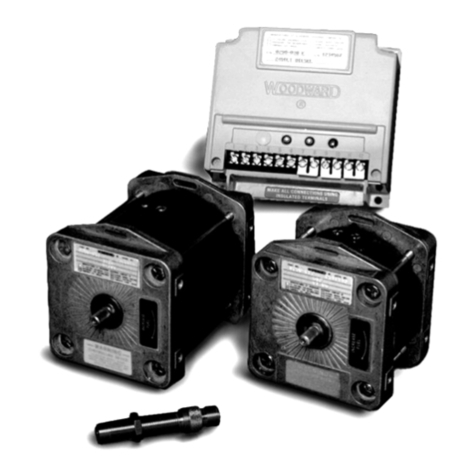
BEIER-Electronic UFR-1230 User manual

GB Speed Controller UFR-1230
28.08.2018 BEIER-Electronic 1
Operating Manual
Speed Controller
UFR-1230
V1.12
BEIER-Electronic
Winterbacher Str. 52/4, 73614 Schorndorf - Weiler
Phone: 07181/46232, Telefax 07181/45732
eMail: modellbau@beier-electronic.de
Internet: http://www.beier-electronic.de/modellbau

GB Speed Controller UFR-1230
2 BEIER-Electronic 28.08.2018
Contents
Contents..................................................................................................................... 2
Description.................................................................................................................. 3
Safety notes ............................................................................................................... 4
Technical data............................................................................................................ 5
Pin assignment........................................................................................................... 6
Wiring diagram........................................................................................................... 7
Installation of speed controller.................................................................................... 8
Connection of speed controller................................................................................... 8
Connection to sound module USM-RC-2 ................................................................. 12
DIP switches............................................................................................................. 13
Load regulation......................................................................................................... 13
Cruise control ........................................................................................................... 14
Brake function .......................................................................................................... 14
Handbrake................................................................................................................ 14
Selection of battery type........................................................................................... 15
Setup (teaching function).......................................................................................... 15
Driving mode ............................................................................................................ 16
Additional functions.................................................................................................. 16
Control channel X3................................................................................................... 18
Simulation of a control stick with switches................................................................ 19
Nautic/Multiswitch..................................................................................................... 20
Switching outputs ..................................................................................................... 21
Short circuit protection at motor output..................................................................... 24
Temperature monitoring........................................................................................... 24
Low voltage monitoring............................................................................................. 25
Current monitoring of outputs................................................................................... 25
Monitoring of proportional inputs/failsafe.................................................................. 25
LEDs on UFR-1230.................................................................................................. 26
Installation of software „UFR-1230 Drive-Teacher“.................................................. 27
How to use the software „UFR-1230 Drive-Teacher“ ............................................... 28
Diagnosis.................................................................................................................. 38
Firmware update....................................................................................................... 40

GB Speed Controller UFR-1230
28.08.2018 BEIER-Electronic 3
Description
The speed controller has been designed specially for RC vehicles with brushed DC
motors, such as trucks.
With the various setting options the speed controller can be easily adjusted to all
model requirements and driving behaviours. All settings can be adjusted with DIP
switches and the software "Drive-Teacher".
The speed controller is equipped with 8 switching outputs to connect LEDs and other
lights directly. In addition the speed controller has an extra output for connecting the
infrared diode from the light module SM-IR-16-2.
The speed controller UFR-1230 has following characteristics:
•Supply voltage 6 – 18 V
•Maximum motor current 30 A (short-term 60 A)
•PWM pulse frequency 20 or 40 kHz
•8 switching outputs for lights (for instance for braking, driving backwards,
parking, flashing)
•Powerful BEC with 5,2 V and 3 A continous current (short circuit proof)
•3 proportional channels (throttle, steering, and control channel)
•2 proportional outputs (output for sound module and steering servo)
•Additional functions (controllable with nautic and multiswitch modules)
•Failsafe in case of receiver signal disturbances (motor stop)
•Protection when switching on supply voltage
•Output for infrared diode for light module SM-IR-16-2 in trailer
•Battery voltage monitoring
•Temperatur monitoring
•Short circuit protection at motor output stage
Options adjustable with DIP switches:
•Load regulation on/off
•Cruise control on/off
•Brake function on/off
•Parking brake on/off
•Battery type: LiPo/other
•Teaching function (setup) for throttle channel on/off

GB Speed Controller UFR-1230
4 BEIER-Electronic 28.08.2018
Additional functions are adjustable with the software "Drive-Teacher" and can be
transferred with the data cable K-USB-2 (optional available):
•Firmware update
•Diagnosis
•Invertion of channels
•Deactivation of low voltage monitoring
•Reduction of driving backwards speed to 50 %
•Selection of PWM pulse frequency between 20 or 40 kHz (for bell-armature
motors)
•Adjustment of load regulation
•Activation / adjustment of inertia
•Activation / adjustment of steering inertia
•Adjustment of hand brake sensitivity
•Activation of emergency stop function
•Limitation of steering angle
•Adjustment of throttle curve
•Configuration of switching outputs (output type, brightness, Xenon effect, etc.)
•Configuration of light switch (controllable with proportional channel)
•Configuration of control channel
•Configuration of nautic / multiswitch modules
•Configuration of servo outputs of light module SM-IR-16-2
Safety notes
•Please read this operating manual carefully and keep it for future use!
•The integrated circuits on the speed controller are sensitive to electrostatic
charge. Therefore it is important that you don’t touch these components,
before discharging yourself (e.g. through a grip onto a grounded device).
•Under certain circumstances unfavourable placement and wiring of the speed
controller in the model may lead to restriction of transmitter range (mainly with
35/40 MHz transmitter).
•The speed controller should only be used with supply voltages that are given
in the technical data.
•Always switch off power before connecting the speed controller!
•The speed controller is not suitable for children under 14 years.

GB Speed Controller UFR-1230
28.08.2018 BEIER-Electronic 5
Technical data
Supply voltage (Ub):
6 – 18 V DC
Power consumption:
Stand-by current: approx. 40 mA
Motor current:
Max. 30 A continous current,
60 A short-term current (1 minute)
BEC voltage:
5,2 V
BEC current:
Max. 3 A continous current,
5 A short-term current (10 seconds)
Proportional inputs:
3 pieces (1,000 – 2,000 ms):
•Throttle channel
•Steering channel
•Control channel (for lights)
Proportional outputs:
2 pieces (1,000 – 2,000 ms):
•Output for sound module
•
Servo output for steering servo
Switching outputs:
8 pieces (npn – open collector),
max. 1,5 A per output, sum of all outputs must no
exceed 3,0 A
Protection features:
•Short circuit protection at motor output stage
•Short circuit protection at switching outputs
•Short circuit protection at BEC
•Temperature monitoring
•Battery voltage monitoring
•Protection while switching on power supply
•Failsafe for proportional inputs
Additional ports:
•Programming interface for data cable
•Port for infrared diode of light module
SM-IR-16-2
Cables for connection:
•For battery: 2 x 2,5 mm², length approx. 15 cm
(with Deans T female connector)
•For Motor: 2 x 2,5 mm², length approx. 15 cm
•For receiver: servo patch 3 x 0,14 mm²,
length approx. 30 cm
Permitted ambient
temperature:
0 – 60 °C
Permitted humidity:
Max. 85 %
Size:
65 x 45 x 23 mm
Weight:
75 g

GB Speed Controller UFR-1230
6 BEIER-Electronic 28.08.2018
1
1
12
2
10
orange
red orange
red
black
Battery + Battery -
Throttle channel
Steering channel
Control channel
Steering servo
Sound module
Switching outputs
+
+
orange
red
red
orange
Data cable
IR-Diode
Battery-
Battery+
Pin assignment
Connections at the speed controller:
Battery
red: battery +, black: battery - (Deans T female connector)
Motor
yellow: motor +, blue: motor -
X1
Proportional input: throttle channel
X2
Proportional input: steering channel
X3
Proportional input: control channel
X4/1
Proportional output: sound module
X4/2
Proportional output: steering servo
X5
Switching outputs 1 – 8
X6/1
Port for data cable K-USB-2
X6/2
Connection for infrared diode of light module SM-IR-16-2

GB Speed Controller UFR-1230
28.08.2018 BEIER-Electronic 7
Battery
6 - 18V
M
+
-
Control
channel
Steering
Throttle
Receiver
grey
purple
blue
green
yellow
orange
red
brown
white / black
+
to
sound
module
X2/1
Steering
servo
Data cable K-USB-2
IR-transmitter diode
for SM-IR-16-2
X1
X2
X3
X4
X5
X6
1 2
21
1
10
Motor
Battery+
Battery-
Wiring diagram

GB Speed Controller UFR-1230
8 BEIER-Electronic 28.08.2018
Installation of speed controller
For a safe installation of the speed controller, we recommend to use Velcro tape on
the UFR-1230 cover.
Pay attention not to connect components and conductor tracks with any metal parts!
This may cause a short circuit, which destroys the speed controller!
Connection of speed controller
Always switch off power before connecting the module!
Connection of supply voltage (battery):
The speed controller is suitable for 6 – 18 V DC. In order to connect the power
supply the red cable is connected to the positive pole of the battery and the black
cable to the negative pole of the battery.
For an easy connection, the speed controller is delivered with a Dean T female
connector.
Pay attention to a correct connection of the supply voltage poles! A wrong
connection destroys the speed controller immediately!!!
Connection of motor:
The yellow cable is used to connect the positive pole of a motor. The blue cabel is
connected to the negative pole of the motor.
In case the driving direction is wrong (forwards and backwards are opposite), you
can change the connection cables of the motor or you can invert the driving direction
in your Sound-Teacher, see page 29.
Connection of receiver (X1, X2 and X3):
3 servo cables (X1 - X3) are soldered to the speed controller UFR-1230, for
connecting the speed controller to the receiver.
Servo cable
Channel of receiver
X1
Throttle channel
X2
Steering channel (optional for indicator lights, bending lights and
steering inertia)
X3
Control channel (optional to control light functions)

GB Speed Controller UFR-1230
28.08.2018 BEIER-Electronic 9
Throttle channel X1 must be connected to the receiver in order to control the pace of
the speed contoller.
Steering channel X2 needs to be connected in case one of the folllowing functions
should be used:
•Activation of indicator lights by steering
•Automatic flashing of indicator lights while steering
•Steering inertia and steering angle limitation
•Transmission of steering signals to light module SM-IR-16-2 via infrared
Control channel X3 needs to be connected in order to trigger light functions at the
speed controller, such as parking light, low/high beam and fog lights or in case the
brake function (DIP switch 3) is activated (to change the driving direction).
The speed controller has its own BEC supply voltage (only with X1) an additional
receiver battery is not required.
In case the BEC voltage of the UFR-1230 should not be used, the red cable from
servo cable X1 and the red servo cable from X4/1 (sound module connection) must
be disconnected.
Connection of sound module (X4/1)
The UFR-1230 has a special output for connecting a sound module (for example the
USM-RC-2). This output X4/1 (lower pins) is connected with a servo patch cable
directly to the throttle channel of the sound module (at the USM-RC-2 it is prop#1,
X2/1). See page 12 for additional information.
Connection of steering servo (X4/2)
To use the steering inertia and the steering angle limitation of the UFR-1230, the
steering servo must be connected to pin X4/2 (upper pins). The steering inertia
needs to be activated with the software Drive-Teacher. With the data cable K-USB-2
the changed configurations can be transferred to the speed controller UFR-1230.
Without using the steering inertia and steering angle limitation the steering servo can
be connected directly to the receiver.
Connection of switching outputs (X5):
To connect the switching outputs we recommend to use the supplied flat ribbon
cable or the terminal clamps AKL-10/AKL-10-W. Other cables and clamps with a size
0,14mm² – 0,5mm² can be used as well.
The speed controller switches always the negative pole to the connected load.
The positive pole is therefore always connected to the load, see page 7 (wiring
diagram).
The joint positive pole for all outputs is at X5 on pin 9 and 10. It is also possible to
connect the load directly to the positive pole of the battery.

GB Speed Controller UFR-1230
10 BEIER-Electronic 28.08.2018
Assignment of flat ribbon cable:
Output
Flat ribbon cable
1
brown
2
red
3
orange
4
yellow
5
green
6
blue
7
purple
8
grey
Positive pole
white
Positive pole
black
When connecting the flat ribbon cable the black cable points up to the edge of the
board.
The switched voltage of the outputs (with 100 % brightness) is always as high as the
supply voltage of the speed controller.
LEDs always require series resistors! Pay attention to the correct polarity. The
resistor values depend on the LED colour and the LED current.
The values below are for standard LEDs with a current of 15 mA.
Supply voltage
Series resistor
6 V
270 Ohm
7,2 V
330 Ohm
8,4 V
470 Ohm
9,6 V
510 Ohm
12 V
680 Ohm
14 V
820 Ohm
16 V
1 kOhm
For an exact calculation you can use a resitor calculator, like
www.leds.de/widerstandsrechner.
If more LEDs should be connected to one output (indicator front and back) it is better
to use for each LED its own resitor. A series connection should be avoided.
General remarks for wiring:
Always use cables with a core diameter of at least 2,5 mm² for connecting the power
supply and the motor. For all other connections, such as lights you can use smaller
cables such as 0.25 mm².

GB Speed Controller UFR-1230
28.08.2018 BEIER-Electronic 11
Unfortunately motors are often strong interference sources, which could disturb other
electronic modules in your model. Therefore all motors should be absolutely
interference-suppressed!
It is important to pay attention to „clean" wire routing. Always use short wires and
avoid any unnecessary loops. The supply voltage wires of the speed controller
should be connected to the driving-battery as direct as possible.
A separate installation of interfering cables (for example motor cables) can achieve
significant improvements.
Connection of infrared (transmitter) diode of light module SM-IR-16-2 (X6/1)
At pin X6/1 (upper pins) the transmitter infrared diode for the light module SM-IR-16-
2 is connected.
All 8 outputs/light signals are transmitted 1:1 from the speed controller to the light
module. The outputs 9 – 12 and the light functions (rotating, flashing and lightning
lights) at output 13 – 16 of the SM-IR-16-2 can be switched with the control channel
X3.
The servo outputs can be controlled by steering (for steerable axles at the trailer) or
by fix (programmed) positions.
The light module SM-IR-16-2 can be connected either to the sound module USM-
RC-2 or to the speed controller UFR-1230.
Connection of data cable K-USB-2 (X6/2)
The data cable K-USB-2 is connected to X6/2 (lower pins).
Following functions require a data cable:
•Transmission of Drive-Teacher configurations
•Read-out configurations of speed controller
•Run diagnosis functions
•Update of firmware
The speed controller is not powered by the data cable. For using the data cable, the
UFR-1230 must be supplied with power via the battery as normal.

GB Speed Controller UFR-1230
12 BEIER-Electronic 28.08.2018
Connection to sound module USM-RC-2
In combination with the sound module USM-RC-2, the throttle channel from the
receiver is connected directly to the speed controller (X1). The sound module (prop
#1, X2/1) is connected with a servo patch cable to X4/1 (lower pins) of the speed
controller and receives information through this connection.
The sound module receives the actual speed information directly from the speed
controller, even if the cruise control and the load regulation are active. The sound
module is operated in digital mode.
Despite using the UFR-1230 brake function, the option „speed controller has a
braking feature“ must be deactivated in the USM-RC-2 Sound-Teacher (configuration
- engine sound).
Digital transmission to sound module
With the Drive-Teacher software V1.10 and higher versions, it is possible to transfer
speed and light data digital to the sound module USM-RC-2. The connection from
X4/1 (speed controller) to X2/1(USM-RC-2) is used in combination with the activation
of the digital communication in the Drive-Teacher (Configuration Speed Controller
Other Digital communication with sound module), see more information on
page 29.
The digital communication offers several advantages:
•The sero point (driving diagram) is always correct
•More precise transfer of speed data
•Additional outputs from the USM-RC-2 can be used for connecting lights, in
case the 8 light outputs at the UFR-1230 are not enough. For this, only the
types for the outputs must be selected in the Sound-Teacher. This works with
these light functions:
oDaytime running light
oParking light
oLow beam headlight
oHigh beam headlight
oIndicator left / right
oBending light left / right
oFog light
oRear fog light
oBrake light
oReversing light
•The sound module monitors all functions of the UFR-1230. For example, if the
speed controller is flashing the sound module activates the corresponding
indicator sound automatically
•No additional wiring is necessary in order to transfer light signals from the
UFR-1230 to the sound module and further to the IR-light module SM-IR-16-2.

GB Speed Controller UFR-1230
28.08.2018 BEIER-Electronic 13
For digital communication at least Sound-Teacher V1.50 is required. You also need
to activate „Digital mode with UFR ESC“ in your Sound-Teacher (Configuration
General General Module configuration).
DIP switches
Following functions can be activated and deactivated with the DIP switches:
Switch
OFF
ON
1
Load regulation off
Load regulation on
2
Cruise control off
Cruise control on
3
Brake function off
Brake function on
4
Handbrake off
Handbrake on
5
Other type of battery
LiPo Battery
6
Normal driving
Setup (teaching) on
All DIP switches can be changed during driving, except of switch 5, which must be
used before turning on power supply.
Load regulation
With DIP switch 1 an optional load regulation can be activated. The speed controller
will check the current driving speed in case the throttle channel position differs from
the actual driving speed due to environmental impacts and will maintain the driving
speed.
For example a model starts to drive up a hill, this requires more throttle to keep the
pace. With the activated load regulation the throttle adjustment is automatically done
by the speed controller when driving up or down a hill.
This effect is particularly visible at a slow/medium driving speed. However, at a very
slow speed the load regulation may reach its limits.
How fast the load regulation should adjust the speed can be set in the Drive-
Teacher.
Depending on the motor the load regulation effect may vary. This function is still in
„development stage“ and we can not guarantee a perfect performance with all motor
types.
The load regulation can also be activated/deactivated (temporarily) with an additional
function (control channel X3). The dip switch 1 position indicates the standard setting
of the load regulation.

GB Speed Controller UFR-1230
14 BEIER-Electronic 28.08.2018
Cruise control
With DIP switch 2 the cruise control can be activated (ON).
With activated cruise control the throttle position controls not any longer the actual
driving speed but the change in speed. In neutral position (throttle stick) the cruise
control keeps the speed.
The speed increases when pressing up the throttle stick and decreases (until
standing) when pressing down.
While driving backwards the handling is the same (just opposite). The model
accelerates when the throttle stick is put down and slows down when it is put up.
The further the throttle stick is moved away from neutral, the stronger the speed
controller accelerates or decelerates.
With activated brake function (DIP switch 3 ON) the throttle stick must be moved up
for acceleration even when driving backwards. Control channel X3 must be used to
put in the reverse gear.
The cruise control can also be activated/deactivated (temporarily) with an additional
function (control channel X3). The dip switch 2 position indicates the standard
setting.
Brake function
With the brake function (DIP switch 3 ON) the vehicle can be slowed down by the
speed controller UFR-1230.
The stronger the throttle stick is pressed down, the stronger the vehicle brakes.
To drive backwards the driving direction must be changes with the control channel
X3. To accelerate backwards (in reverse gear) the throttle stick must be pressed up.
Handbrake
With activated handbrake (DIP switch 4 ON) the vehicle is stopped by the EMF
motor brake to prevent a roll away.
When accelerating, the handbrake is deactivated automatically. In the Drive-Teacher
you can set the handbrake hardness and wether it should be activated only while
standing or as soon as the throttle channel is in neutral position and the vehicle is
still rolling out.

GB Speed Controller UFR-1230
28.08.2018 BEIER-Electronic 15
However, the EMF brake is not as effective as a mechanical brake. At a steep incline
the vehicle may roll away despite the handbrake.
Selection of battery type
With a LiPo battery DIP switch 5 must be set ON. With all other types of batteries the
switch is OFF.
The battery setting is important for a correct low voltage monitoring (see page 25).
Setup (teaching function)
With the teaching function important parameters can be synchronised between the
radio and the speed controller, such as:
•Neutral position of throttle channel X1
•Neutral position steering channel X2
•Neutral position of control channel X3
•Maximum position of throttle channel X1
•Minimal position of trottle channel X1
The speed controller is delivered with following standard setting: neutral position (1,5
ms), minimal position (1,0 ms) and maximal position (2,0 ms).
We recommend to „teach“ the speed controller with the radio at least once. The
motor is not triggered during teaching, except of the peeper in step 4, 5 and 6.
1. Connect throttle channel X1, steering channel X2 and control channel X3 to
your receiver.
2. All channels must be in neutral position. Turn on receiver.
3. Put DIP switch 6 to ON.
4. Turn on supply voltage at speed controller the green LED is flashing fast. If
there is a good signal at throttle channel X1 the neutral position of the throttle
stick is saved. If the red LED is flashing, the speed controller can not detect a
correct signal at X1. Please check all connections again.
5. For a short while give full throttle and press the stick all the way up. Return to
neutral position the blue LED flashes two times and lights permanently
afterwards.
6. For 10 seconds press the throttle stick down and give full throttle backwards
and return to neutral position the blue LED flashes three times. The green
LED lights permanently afterwards.
7. The setup is completed. Turn the DIP switch 6 OFF.

GB Speed Controller UFR-1230
16 BEIER-Electronic 28.08.2018
Driving mode
There are 4 driving modes, combining the functions cruise control and braking.
Depending on the driving mode the throttle channel is used differently:
No cruise control
No brake function
No cruise control
with brake
with cruise control
no brake function
with cruise control
with brake
driving forwards
driving backwards
driving forwards
and backwards
braking
forwards accelerating
/ backwards slowing
down
forwards slowing
down / backwards
accelerating
forwards and
backwards
accelerating
slowing down and
braking
DIP switch 2: OFF
DIP switch 3: OFF
DIP switch 2: OFF
DIP switch 3: ON
DIP switch 2: ON
DIP switch 3: OFF
DIP switch 2: ON
DIP switch 3: ON
With activated braking function (DIP switch 3 ON) the driving direction must be
changed by control channel X3.
It is not always practical to drive backwards using the cruise control.
For this reaseon, it is possible to turn off the cruise control automatically while driving
backward. By selecting the option the cruise control is only active while driving
forwards.
Additional functions
Following additional functions can be triggered with control channel X3:
•Triggering outputs 1 – 8 static
•Daytime running light
•Low beam headlight
•High beam headlight
•Fog light

GB Speed Controller UFR-1230
28.08.2018 BEIER-Electronic 17
•Rear fog light
•Indicator left
•Indicator right
•Hazard light
•Light switch +
•Light switch -
•Changing driving direction
•Changing to throttle curve 2
•Load regulation on/off
•Cruise control on/off
•Inertia off
•Inertia light
•Inertia medium
•Inertia heavy
•Steering limit off
•SM-IR-16-2: servo 1 - position #1
•SM-IR-16-2: servo 1 - position #2
•SM-IR-16-2: servo 2 - position #1
•SM-IR-16-2: servo 2 - position #2
•SM-IR-16-2: output 9
•SM-IR-16-2: output 10
•SM-IR-16-2: output 11
•SM-IR-16-2: output 12
•SM-IR-16-2: rotating light
•SM-IR-16-2: flasher
•SM-IR-16-2: running light
•Flash
With a normal proportional channel a maximum of 8 functions can be triggered (see
page 32).
To trigger more additional functions we recommend to use a radio with nautic /
multiswitch module.
With the function „output 1 – 8“ the outputs are always switched as static (on/off),
independet from the defined output type. Flashing lights, such as indicators must be
switched with the specific light function „indicator left“ and „indicator right“ and not by
„output 1 – 8“.
The outputs 9 – 12 of the light module SM-IR-16-2 can only be switched as static
with a light intensity of 100 %. An adjustment or change is not possible.

GB Speed Controller UFR-1230
18 BEIER-Electronic 28.08.2018
Control channel X3
With control channel X3 lights and other additional functions can be switched (see
page 16). With the activated option „brake function“ (DIP switch 3) the driving
direction must be changed with control channel X3.
A proportional channel is divided in 5 areas, namely A, B, N, C and D, which indicate
the possible control stick positions.
Area N is the middle position and therefore neutral with no function.
Area A is on the left and D on the right side. Some radios have an opposite division.
In this case the channel must be inverted at the radio or with the Drive-Teacher to
trigger functions (left/right indicator) correctly.
Standard setting of control channel X3:
A
B
N
C
D
Short in
position
Indicator left
on/off
Indicator right
on/off
Long in
position Light switch - Change driving
direction Hazard light
on/off Light switch +
The assignment of functions can be changed with the Drive-Teacher (see page 32).
If the function „automatic indicator lights while turning“ is activated in the Drive-
Teacher the indicator lights can only be activated with the steering channel (X2) and
no longer with the control channel (X3)!
The driving direction can only be changed while standing.

GB Speed Controller UFR-1230
28.08.2018 BEIER-Electronic 19
Simulation of a control stick with switches
In most cases the control sticks of a radio are
occupied with other functions. Therefore you
need a different option to control the functions
of channel X3.
With one free channel and two switches the
different possitions of a poti / control stick can
be simulated. You can find the circuit plan on
the right. Example: if you press switch S1
position A of a control stick is simulated and the
programmed function (light) is activated or
deactivated.
For this setting you need 6 resitors and 4
switches (or 2 switches with neutral position).
You can built the circuit easily on a board in a
short time.
The resistor values should be sufficient for the
most comercially sold radios. The 5 thresholds
can be adjusted with the Drive-Teacher.
Depending on your radio type the circuit as well
as the installation might be different.
With some radios (Futaba/Robbe) you might
need one additional 68k Ohm resistor for
neutral „S“.
Hint:
The correct function can be checked with the diagnosis function of the Drive-
Teacher.
You can also buy „ready to use“ switch modules in our online shop. For Robbe
radios we recommend switch SMS-R and for all other types of radios SMS-G.

GB Speed Controller UFR-1230
20 BEIER-Electronic 28.08.2018
Nautic/Multiswitch
All additional functions of the UFR-1230-D can be controlled with nautic and
multiswitch modules.
Following switch modules can be used with the speed controller UFR-1230:
•BEIER-Electronic NMS-16-R, NMS-16-G and NMS-24-G
•BEIER-Electronic EMS-16-R, EMS-16-G and EMS-24-G
•BEIER-Electronic MSC-8-C, MSC-10-C and MSC-8-C-LCD
•Graupner Nautic-Expert Module (Nr. 4108), Multikanal
•Robbe Multi-Switch Module (Nr. 8084, 8101, 8413, F1511)
•Mergen/CP 12-Channel and 16-Channel Multiswitch
Some of the new radio types have „software-nautic-switches“ which might be used
as well. For more information please check the operating manual of your radio.
To use the nautic mode the option must be activated in the Drive-Teacher.
For each switch position additional functions (see page 16) can be set in the Drive-
Teacher (see page 32). When pressing the switch the assigned function is activated.
With the option „memory“ the function stays activated until the switch is pressed
again.
To use a nautic/multiswitch module the servo channel X3 of the UFR-1230 must be
connected to the correct receiver output (corresponding to the used transmitter
input).
If the UFR-1230 receives correct data from the nautic/multiswitch module, the blue
LED flashes regularly in short intervalls. With EMS modules the blue LED only lights
as long as one of the switches is pressed.
If the blue LED is not flashing regularly or the nautic/multiswitch module is not
working properly, please check the settings at your radio. In the operating manual of
your radio you can read more about the required settings for a nautic module.
At radios with Jeti Duplex 2,4 GHz the „output period“ of the receiver must be set
with the Jeti-Box to „by transmitter“ or „auto“. Further important settings are: ATV
high limit: 2,20 ms, ATV low limit: 0,80 ms.
Table of contents
Other BEIER-Electronic Controllers manuals

BEIER-Electronic
BEIER-Electronic SV3-1-8Z User manual
BEIER-Electronic
BEIER-Electronic SFR-1-HL User manual

BEIER-Electronic
BEIER-Electronic SFR-1 User manual
BEIER-Electronic
BEIER-Electronic UFR-1230-D User manual

BEIER-Electronic
BEIER-Electronic SV1-2-10Z User manual
BEIER-Electronic
BEIER-Electronic SFR-1-D User manual
