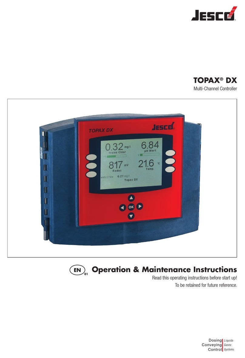
Jesco TOPAX L1 Instruction Manual

TOPAX L1 / L4 / L5
For free chlorine, chlorine dioxide or hydrogen peroxide
EN 02 Operation &
Maintenance Instructions
Read these operation and maintenance instructions
before start up!
To be held for future reference.
Dosing
Conveying
Control
Liquids
Gases
Systems

2 | Operation & Maintenance Instructions TOPAX L1/L4/L5 | Table of Contents
Table of Contents
1. General and Safety Instructions.......................................................................... 4
1.1 General.......................................................................................................... 4
1.2 Warning symbols used in this Operation & Maintenance Manual........................ 4
1.3 Qualification and training of personnel ............................................................. 4
1.4 Important safety instructions ........................................................................... 4
1.5 Hazards due to non-compliance with safety instructions ................................... 5
1.6 Safe operation................................................................................................ 5
1.7 Safety instructions for the owner/operator........................................................ 5
1.8 Safety instructions for inspection-, maintenance-, and installation work ............. 5
1.9 Unauthorized modifications and production of spare parts................................. 6
1.10 General notes of instruction!.......................................................................... 6
1.11 Scope of delivery.......................................................................................... 6
1.12 Disposal....................................................................................................... 6
1.13 Overview of device functions ......................................................................... 7
1.14 Technical data.............................................................................................. 8
2. Device Installation and Connection .................................................................... 9
2.1 Dimensions.................................................................................................. 10
2.2 Installation of built-in casing.......................................................................... 11
2.3 Installation of wall-mounted casing................................................................ 12
2.4 terminal connection diagram of built-in casing ............................................... 13
2.5 terminal connection diagram of built-in casing ............................................... 15
3. Instructions for Device Operation ..................................................................... 17
3.1 Parameter settings ....................................................................................... 18
3.2 Menu overview............................................................................................. 19
4. Password Codes and Languages ...................................................................... 20
5. Metering Unit Settings....................................................................................... 21
5.1 Calibration ................................................................................................... 21
5.2 Temperature compensation ........................................................................... 23
6. Controller Unit Settings ..................................................................................... 24
6.1 ON/OFF-Controller........................................................................................ 25
6.2 P-/PI-Controller as pulse-frequency controller ................................................ 26
6.3 P-/PI-Controller as pulse-pause controller...................................................... 27
6.4 Controller activation and deactivation............................................................. 28

Table of Contents | Operation & Maintenance Instructions TOPAX L1/L4/L5 | 3
6.5 Turn-on delay............................................................................................... 28
6.6 External controller stop ................................................................................. 28
6.7 Manual relay control ..................................................................................... 29
6.8 Alarm .......................................................................................................... 30
7. Data Readout ..................................................................................................... 31
7.1 Current output.............................................................................................. 32
7.2 RS485 Serial interface (optional) ................................................................... 32
7.3 Assembly of a Data Network (TopView)........................................................... 32
8. Operation and Maintenance .............................................................................. 34
9. Service ............................................................................................................... 35
9.1 Device data.................................................................................................. 35
9.2 Analog inputs ............................................................................................... 35
9.3 Erase Settings (Reset)................................................................................... 35
10. Error advisory .................................................................................................. 36
11. Index................................................................................................................. 37
12. Declaration of conformity................................................................................ 40
13. Revision............................................................................................................ 42
14. Warranty Application....................................................................................... 43

4 | Operation & Maintenance Instructions TOPAX L1/L4/L5 | General and Safety Instructions
1. General and Safety Instructions
1.1 General
This Operation & Maintenance Manual contains basic information to be noted during in-
stallation, operation and maintenance. It is therefore essential that the contractor read the
manual before installing and commissioning the pump/system as well as by the relevant
operating personnel/owner of the pump/system. It must remain accessible at the dosing
pump/system for reference at all times.
In addition to the general safety instructions under this main heading of Safety, the special
safety precautions outlined another section must also be observed.
1.2 Warning symbols used in this Operation & Maintenance Manual
This Operation & Maintenance Manual contains vital information, which may endanger
people, the environment and the dosing pump/system if disregarded. These statements
are identified by the following symbols:
DANGER! Refers to an imminent danger. Non-compliance can lead to death or serious
injury.
WARNING! Refers to a potentially hazardous situation. Non-compliance can lead to death
or serious injury.
CAUTION! Refers to a potentially hazardous situation. Non-compliance can lead to minor
injury or property damage.
NOTICE! or INFORMATION! Appear in conjunction with safety instructions, which may
endanger the pump/system and its operation if disregarded.
IMPORTANT! Draws attention to supplementary information to make the work easier and
ensure trouble free operation.
1.3 Qualification and training of personnel
The personnel employed for installation, operation, inspection and maintenance work
must be qualified to do so. The areas of responsibility, competence and supervision of the
personnel must be precisely defined by the owner. Personnel who do not have the required
knowledge must be duly rained and instructed. If necessary, this training can also be
provided by the manufacturer/supplier on behalf of the dosing pump’s owner. In addition,
the owner of the system must ensure that the relevant personnel are fully familiar with and
have understood the contents of this Operation & Maintenance Manual.
1.4 Important safety instructions
When installing and using this electrical equipment, basic safety precautions should
always be followed, including the following:
1.) Read and follow all instructions!
2.) WARNING! To reduce risk of injury, do not permit children to use this product
unless they are closely supervised at all times.
WARNING!

General and Safety Instructions | Operation & Maintenance Instructions TOPAX L1/L4/L5 | 5
3.) WARNING! Risk of electric shock. Connect only to a grounding type receptacle
protected by a ground-fault circuit-interrupter (GFCI). Contact a qualified electri-
cian if you cannot verify that the receptacle is protected by a GFCI.
4.) Do not bury the cord. Locate the cord to minimize abuse from lawn mowers, hedge
trimmers, and other equipment.
5.) WARNING! To reduce the risk of electric shock, replace damaged cord imme-
diately.
6.) WARNING! To reduce the risk of electric shock, do not use an extension cord
to connect the unit to the electricity supply; provide a properly located outlet.
7.) Save these instructions!
1.5 Hazards due to non-compliance with safety instructions
Failure to comply with safety instructions may endanger not only people, but also the
environment and the dosing pump/system. Non-compliance with the safety instructions
can lead to the loss of all entitlement to damages.
The following hazard in particular may arise:
• Danger to people due to electrical, mechanical and chemical effects.
• Failure of system functions.
• Danger to the environment due to leakage of hazardous substances.
1.6 Safe operation
The safety instructions in this Operation & Maintenance Manual must be observed.
The owner is responsible for ensuring the compliance with local safety regulations.
1.7 Safety instructions for the owner/operator
Leakages (e.g. due to ruptures in the lining) of hazardous substances (e.g. toxic or
abrasive) must be discharged in such a way as to exclude all danger to people and the
environment. Statutory regulations must be observed.
Danger due to electric current must be excluded (for further details, refer to the German
VDE standards as well as local regulations or chapter 1.4).
1.8 Safety instructions for inspection-, maintenance-, and installation work
The owner must ensure that all inspection, maintenance and installation work is under-
taken by authorized and duly qualified personnel who have also studied this Operation &
Maintenance Manual.
The dosing pump must always come to a complete stop before starting any work on the
pump. The procedure specified in this Operation & Maintenance Manual for shutting down
the Dosing/pump/system must be observed without fail.
Dosing pumps or systems in contact with potentially harmful media must be decontami-
nated.
WARNING!
WARNING!
WARNING!

6 | Operation & Maintenance Instructions TOPAX L1/L4/L5 | General and Safety Instructions
All safety mechanisms and guards must be refitted and reactivated as the work is comple-
ted.
1.9 Unauthorized modifications and production of spare parts
The device may only be modified or converted in consultation with the manufacturer. Ge-
nuine spare parts and accessories authorized by the manufacturer ensure greater safety.
The use of other parts can void the liability for the subsequent consequences.
1.10 General notes of instruction!
Measuring cables must not be laid parallel or close to power supply or high-voltage current
lines. Interferences would mutilate the measurement. At close distances, power supply and
measuring lines may only cross at a 90° angle.
The admissible length of the measuring cables must be adhered to with regard to the sen-
sor used. It is of decisive importance whether high-impedance (e.g. pH value) or low-im-
pedance (e.g. free chlorine sensor) measurements are carried out. In the case high-impe-
dance measurements, make sure that the (plug) connections are clean and dry (plug) and
the lines do not become brittle due to sharp buckling. The screened cables normally used
for such measuring lines must be handled according to the prescribed quality. Screening
may only be connected to ground at one end of the cable (preferably at the controller).
Interface lines must be twisted and screened (see recommended cables).
IMPORTANT!
If possible, a continuous cable from sensor to measuring input should be used.
An extension of the cable by plugs or terminal socket increases the risk of
disturbances due to contamination, humidity or excessive transition resistances.
1.11 Scope of delivery
IMPORTANT!
Please unpack the dosing pump and ordered accessories with great care in or-
der not to miss any small parts. Immediately compare the scope of delivery with
the delivery note. The cause of any discrepancies must be determined.
1.12 Disposal
Should the device need to be permanently taken out of operation, please bear in mind that
it contains electrolytic capacitors and must therefore be disposed of accordingly.
IMPORTANT!
IMPORTANT!

General and Safety Instructions | Operation & Maintenance Instructions TOPAX L1/L4/L5 | 7
1.13 Overview of device functions
Metering Unit
TOPAX L1 TOPAX L4 TOPAX L5
Free chlorine
0.0 - 4.0 mg/l Cl2
Chlorine dioxide
0.0 - 20.0 mg/l ClO2
Hydrogen peroxide
0.0 - 100.0 mg/l H2 O2
Temperature -30.0 – +140.0 °C
Displays Measurement values with units
Temperature with units
Status signal sensor, calibration, controller & alarm
Temperature
compensation
manual or automatic with Pt100
Controller Unit
Switch points 2 switch points with programmable effective direction
Controller variants IN/OUT-Controller, with optional hysteresis
P-Controller as pulse-pause, pulse-frequency or continuous output controller
PI-Controller as pulse-pause, pulse-frequency or continuous output controller
Hysteresis Freely adjustable over the metering range
P-Range XPFreely adjustable over the metering range
Integral time TN0 – 2000 sec.
Minimum pulse 0.1 – 9.9 sec.
Puls+pause-time 02 – 99 sec.
Pulse frequency 100 – 7200 pulses/h
Turn-on delay 0 – 200 sec.
Alarm function min. and max. threshold values und delay time
Connections
Relays 3 potential free contacts (2x controller, 1x alarm)
6 A, 250 V, max. 550 VA
Analog output 0/4-20 mA electrically isolated
max. load 500 Ohm
Analog inputs 1 Measurement input for Cl2or ClO2
1 Measurement input for Pt100
Digital input water deficiency safety
Digitale Interfaces
(Optional)
RS485, Baud rate 9600, dataformat 8Bit,
1start and 1stop bit, no even parity

8 | Operation & Maintenance Instructions TOPAX L1/L4/L5 | General and Safety Instructions
1.14 Technical data
Feature Built-in casing Wall-mounted casing
Installation site in control cabinet on panel or wall
Dimensions 96 x 96 x 127 mm
(W x H x D)
165 x 160 x 80 mm
(W x H x D)
Weight 0.8 kg 1.0 kg
Connections Plug terminals for wiring up to
max. 1.5 mm2
spring clamps for wiring up to max.
1.5 mm2
Protection rating front IP54, with front door IP55 IP65
Supply voltage 230 V +6/-10%, 50/60 Hz
alternating 110 V 50/60 Hz or 24 V 50/60 Hz
Internal safety none 230 V: 63 mA delayed
110 V: 125 mA delayed
24 V: 800 mA semi-delayed
Performance input 10 VA
Displays 2-row LCD display, 2x16 characters, backlit,
display of measurement values with relative units, additional temperature
display, display of relay position
Current output 0/4-20 mA, electrically isolated, max. load 500 Ohm
Interfaces (Option) RS485, baud rate 9600, data format 8 bit, 1 start and 1 stop bit
Controller ON/OFF-Controller with optional hysteresis, P- or PI-Controller as pulse-
pause or pulse-frequency controller or continuous output controller, dual-
direction PI-control possible, adjustable Turn-on delay, manual operation
of relays, controller stop
by external switch or gauge (water deficiency safety)
Switch points 2 switch points, free set point within the measurement range
Alarm function with minimum and maximum limit values and time delay
Contact load 6 A/ 250 V, max. 550 VA ohmic resistive load (with RC protective circuit)
Operating tempe-
rature
0 – 50°C
Storage temperature -20 – 65°C
Atmospheric humidity 0 – 90% non-condensing

Device Installation and Connection | Operation & Maintenance Instructions TOPAX L1/L4/L5 | 9
2. Device Installation and Connection
Installation
Schematic diagrams and dimensions are provided over the next few pages.
An opening of 92x92mm is necessary for the device casing.The device is to be inserted
from the front and fastened with the lock-on clips provided on delivery.
The wall mount casing can be hung up or pushed under into the mounting slots. It must
then be fastened on with two screws.
CAUTION
The device assembly site should be chosen such that the device is not subject to
any mechanical load or chemical exposure!
Please note that the corresponding protection classes are:
Built-in casing: IP54 for the front end, with IP55 at the front door
Wall-mounted casing: IP65 (when the clamp cover is closed)
Connections
Connection diagrams are provided on the following pages.
Please be aware of the supply voltage indicated on the rating plate at all times.
CAUTION
Input, output, and control lead wires and cables must always be installed sepa-
rated from one another and, above all, separated from high voltage lines!
All input and output wires and cables need to be shielded. The shielding can only be
applied on one side.
Potentiostatic measurement is sensitive to parasitic induction. Be sure to use a special,
double-shielded cable. The membrane sensors are shipped with the cable included.
For Pt100 temperature sensor connection, be sure to use a heavy gauge cable with the
lowest resistance possible.
When connecting to the relays, bear in mind that inductive loads need to be interference-
suppressed. If this is not possible, the device terminal strip relay contacts need to be
provided with an RC-protective circuit. With direct current voltage, the relays or contactor
coil need to be interface-suppressed using a freewheeling diode.
Current up to Capacitor C Resistance R
60 mA 10 nF 260 V 390 Ohm 2 Watt
70 mA 47 nF 260 V 22 Ohm 2 Watt
150 mA 100 nF 260 V 47 Ohm 2 Watt
1,0 A 220 nF 260 V 47 Ohm 2 Watt
R
C
CAUTION!
CAUTION!

10 | Operation & Maintenance Instructions TOPAX L1/L4/L5 | Device Installation and Connection
2.1 Dimensions
Built-in Casing
Option: Front door
Wall-mounted Casing

Device Installation and Connection | Operation & Maintenance Instructions TOPAX L1/L4/L5 | 11
2.2 Installation of built-in casing
Prepare an opening of 92
x 92 mm.
Insert the device from the
fore end firmly, and fixed
it on using the appropriate
lock-on clips provided on
delivery.
Use a screwdriver to adjust
the lock-on clip screws
until the device is firmly in
place.

12 | Operation & Maintenance Instructions TOPAX L1/L4/L5 | Device Installation and Connection
2.3 Installation of wall-mounted casing
First, remove the terminal
covering.
Prepare three drill holes
(max. M5). Check the top
hole, to ensure that the
wall-mount casing can
either be safely hung on or
pushed under. If it is hung
on, the top hole must be
120 mm above the bottom
two. If it is pushed under,
this distance must be 135
mm.
In both cases the screws
must protrude outwards at
least 3mm.
Hang the device onto the
top screw or push it under,
then fix it on via the two
bottom screws. Either fit
the terminal covering back
on, or proceed directly with
the various connections.

Device Installation and Connection | Operation & Maintenance Instructions TOPAX L1/L4/L5 | 13
2.4 terminal connection diagram of built-in casing
Electrode/
Clips
Potentiostatic
Type PM-J
Potentiostatic-
Type PM-K
Amperometric Hydrogen
peroxide
1 = Shield
2 = Measuring-
3 = Reference-
4 = Counter-
electrode
= -
= Gold- (violet)
= (black)
= stainless steel- (red)
elektrode
= -
= (Pin 1)
= (Pin 2)
= (Pin 3)
= -
= Platin- (rot)
= Brigde to 4
= Copper- (blue)
or Silver electrode
= Shield
= (brown)
= (white)
= green (blue)
TOPAX L1 (Cl2) X (<4 mg/l) X (>4 mg/l) X -
TOPAX L4 (ClO2) X (<4 mg/l) X (>4 mg/l) - -
TOPAX L5 (H2O2) - - - X
Connection Terminals Directions
Pt100 5 + 6
Analog Output 9 + 10 9 = +, 10 = -, maximum 500 Ohm load
Digital Input 11 + 12 11 = +, 12 = -, external controller stop or water deficiency
Relay 1 18 + 19
Relay 2 20 + 21
Relay 3 22 + 23 Alarm-Relay
Power Supply 24 + 25 + 26 Check indications on rating plate!
RS485
(Optional)
Sub-D 3 = +, 8 = -
Sub-D 4/7 Bridge circuits = termination impedance activated
Terminal connection of electrodes
Potentiostatic electrode, Type PM-J, <4 mg/l
1
2
3
5
4
6
7
8
9
10
11
12
13
14 1
2
3
4
5
9
8
7
6
15
16
17
18
19
20
21
22
23
L
N
PE
Relay 1
Relay 2
Relay 3
24
25
26
Measurement, Gold electrode (violet)
Reference electrode (black)
Counter, stainless steel electrode (red)
RS 485
(OPTION)
Measurement, platinum electrode (red)
Copper (blue) or silver electrode (violet)
1
2
3
5
4
6
7
8
9
10
11
12
13
14 1
2
3
4
5
9
8
7
6
15
16
17
18
19
20
21
22
23
L
N
PE
Relay 1
Relay 2
Relay 3
24
25
26
RS 485
(OPTION)
Shield
1
2
3
5
4
6
7
8
9
10
11
12
13
14 1
2
3
4
5
9
8
7
6
15
16
17
18
19
20
21
22
23
L
N
PE
Relay 1
Relay 2
Relay 3
24
25
26
RS 485
(OPTION)
Measurement electrode (brown)
Reference electrode (white)
Counter electrode (green / blue)

14 | Operation & Maintenance Instructions TOPAX L1/L4/L5 | Device Installation and Connection
Terminal connection of electrodes
Amperometric electrode
Hydrogen peroxide electrode
1
2
3
5
4
6
7
8
9
10
11
12
13
14 1
2
3
4
5
9
8
7
6
15
16
17
18
19
20
21
22
23
L
N
PE
Relay 1
Relay 2
Relay 3
24
25
26
Measurement, Gold electrode (violet)
Reference electrode (black)
Counter, stainless steel electrode (red)
RS 485
(OPTION)
Measurement, platinum electrode (red)
Copper (blue) or silver electrode (violet)
1
2
3
5
4
6
7
8
9
10
11
12
13
14 1
2
3
4
5
9
8
7
6
15
16
17
18
19
20
21
22
23
L
N
PE
Relay 1
Relay 2
Relay 3
24
25
26
RS 485
(OPTION)
Shield
1
2
3
5
4
6
7
8
9
10
11
12
13
14 1
2
3
4
5
9
8
7
6
15
16
17
18
19
20
21
22
23
L
N
PE
Relay 1
Relay 2
Relay 3
24
25
26
RS 485
(OPTION)
Measurement electrode (brown)
Reference electrode (white)
Counter electrode (green / blue)
1
2
3
5
4
6
7
8
9
10
11
12
13
14 1
2
3
4
5
9
8
7
6
15
16
17
18
19
20
21
22
23
L
N
PE
Relay 1
Relay 2
Relay 3
24
25
26
Measurement, Gold electrode (violet)
Reference electrode (black)
Counter, stainless steel electrode (red)
RS 485
(OPTION)
Measurement, platinum electrode (red)
Copper (blue) or silver electrode (violet)
1
2
3
5
4
6
7
8
9
10
11
12
13
14 1
2
3
4
5
9
8
7
6
15
16
17
18
19
20
21
22
23
L
N
PE
Relay 1
Relay 2
Relay 3
24
25
26
RS 485
(OPTION)
Shield
1
2
3
5
4
6
7
8
9
10
11
12
13
14 1
2
3
4
5
9
8
7
6
15
16
17
18
19
20
21
22
23
L
N
PE
Relay 1
Relay 2
Relay 3
24
25
26
RS 485
(OPTION)
Measurement electrode (brown)
Reference electrode (white)
Counter electrode (green / blue)

Device Installation and Connection | Operation & Maintenance Instructions TOPAX L1/L4/L5 | 15
2.5 terminal connection diagram of built-in casing
Electrode/
Clips
Potentiostatic
Type PM-J
Potentiostatic
Type PM-K
Amperometric Hydrogen
peroxide
1 = Shield
2 = Measuring-
3 = Reference-
4 = Counter-
electrode
= -
= Gold- (violet)
= (black)
= stainless steel- (red)
elektrode
= -
= (Pin 1)
= (Pin 2)
= (Pin 3)
= -
= Platin- (rot)
= Brigde to 4
= Copper- (blue)
or Silver electrode
= Shield
= (brown)
= (white)
= green (blue)
TOPAX L1 (Cl2) X (<4 mg/l) X (>4 mg/l) X -
TOPAX L4 (ClO2) X (<4 mg/l) X (>4 mg/l) - -
TOPAX L5 (H2O2) - - - X
Connection Terminals Directions
Temperature 6 + 7 Pt100
Display Trimmer for adjustment of display contrast
Analog Output 11 + 12 11 = +, 12 = -, maximum 500 Ohm load
Relay 1 14 + 15
Relay 2 16 + 17
Relay 3 18 + 19 Alarm-Relay
Power supply 20 + 21 + 22 Check indications on rating plate!
RS485 (Opti-
onal)
23 + 24 23 = -, 24 = +
Jumper plugged in = termination impedance activated
Digital Input 26 + 27 26 = +, 27 = -, external controller stop or water deficiency
Terminal connection of electrodes
Potentiostatic electrode, Type PM-J, <4 mg/l
11
7
1
2
3
4
5
6
12
13
GND
Temperature
Pt 100
14
15
16
17
18
19
20
21
22
L
N
PE
GND
0/4 - 20 mA
RS 485
Measurement, gold electrode (violet)
Reference electrode (black)
23
24
25
-+
GND
26
27
28
GND
GND
+ -
Conter, stainless steel electrode (red)
Jumper RS 485
Termination impedance
11
7
1
2
3
4
5
6
12
13
GND
14
15
16
17
18
19
Relay 1
Relay 2
Relay 3
20
21
22
L
N
PE
Power Supply
GND
RS 485
Platinum electrode (red)
Copper (blue) or silver (violet) electrode
23
24
25
-+
GND
26
27
28
GND
GND
+ -
water deficiency
Jumper RS 485
Termination impedance
water deficiency
Relay 1
Relay 2
Relay 3
Analog. Outp.
Power Supply
11
7
1
2
3
4
5
6
12
13
GND
14
15
16
17
18
19
Relay 1
Relay 2
Relay 3
20
21
22
L
N
PE
Power Supply
GND
RS 485
23
24
25
-+
GND
26
27
28
GND
GND
+ -
water deficiency
Jumper RS 485
Termination impedance
Shield
Measurement electrode (brown)
Reference electrode (white)
Counter electrode (green / blue)
Display
Temperature
Pt 100
0/4 - 20 mA
Analog. Outp.
Display
Temperature
Pt 100
0/4 - 20 mA
Analog. Outp.
Display

16 | Operation & Maintenance Instructions TOPAX L1/L4/L5 | Device Installation and Connection
Terminal connection of electrodes
Amperometric electrode
Hydrogen peroxide electrode
11
7
1
2
3
4
5
6
12
13
GND
Temperature
Pt 100
14
15
16
17
18
19
20
21
22
L
N
PE
GND
0/4 - 20 mA
RS 485
Measurement, gold electrode (violet)
Reference electrode (black)
23
24
25
-+
GND
26
27
28
GND
GND
+ -
Conter, stainless steel electrode (red)
Jumper RS 485
Termination impedance
11
7
1
2
3
4
5
6
12
13
GND
14
15
16
17
18
19
Relay 1
Relay 2
Relay 3
20
21
22
L
N
PE
Power Supply
GND
RS 485
Platinum electrode (red)
Copper (blue) or silver (violet) electrode
23
24
25
-+
GND
26
27
28
GND
GND
+ -
water deficiency
Jumper RS 485
Termination impedance
water deficiency
Relay 1
Relay 2
Relay 3
Analog. Outp.
Power Supply
11
7
1
2
3
4
5
6
12
13
GND
14
15
16
17
18
19
Relay 1
Relay 2
Relay 3
20
21
22
L
N
PE
Power Supply
GND
RS 485
23
24
25
-+
GND
26
27
28
GND
GND
+ -
water deficiency
Jumper RS 485
Termination impedance
Shield
Measurement electrode (brown)
Reference electrode (white)
Counter electrode (green / blue)
Display
Temperature
Pt 100
0/4 - 20 mA
Analog. Outp.
Display
Temperature
Pt 100
0/4 - 20 mA
Analog. Outp.
Display
11
7
1
2
3
4
5
6
12
13
GND
Temperature
Pt 100
14
15
16
17
18
19
20
21
22
L
N
PE
GND
0/4 - 20 mA
RS 485
Measurement, gold electrode (violet)
Reference electrode (black)
23
24
25
-+
GND
26
27
28
GND
GND
+ -
Conter, stainless steel electrode (red)
Jumper RS 485
Termination impedance
11
7
1
2
3
4
5
6
12
13
GND
14
15
16
17
18
19
Relay 1
Relay 2
Relay 3
20
21
22
L
N
PE
Power Supply
GND
RS 485
Platinum electrode (red)
Copper (blue) or silver (violet) electrode
23
24
25
-+
GND
26
27
28
GND
GND
+ -
water deficiency
Jumper RS 485
Termination impedance
water deficiency
Relay 1
Relay 2
Relay 3
Analog. Outp.
Power Supply
11
7
1
2
3
4
5
6
12
13
GND
14
15
16
17
18
19
Relay 1
Relay 2
Relay 3
20
21
22
L
N
PE
Power Supply
GND
RS 485
23
24
25
-+
GND
26
27
28
GND
GND
+ -
water deficiency
Jumper RS 485
Termination impedance
Shield
Measurement electrode (brown)
Reference electrode (white)
Counter electrode (green / blue)
Display
Temperature
Pt 100
0/4 - 20 mA
Analog. Outp.
Display
Temperature
Pt 100
0/4 - 20 mA
Analog. Outp.
Display

Instructions for Device Operatio | Operation & Maintenance Instructions TOPAX L1/L4/L5 | 17
3. Instructions for Device Operation
1 Measurement value
2 Relay 1 activation mode
3 Relay 2 activation mode
Relais OFF
Relais ON
4 Temperature
5 Controller operation mode
AUTO: Controller ON
MANUAL: Controller OFF
(Manual relay operation)
6 Direction indicator
7 LEFT arrow key ()
8 UP arrow key ()
9 DOWN arrow key ()
10 RIGHT arrow key ()
11 „ESC“ key
Once switched on, the device will initially display the measuring value data with the opera-
ting mode of the controller (Auto/Manual) and the activation mode of relays S1 and S2.
It is possible to scroll through the menu using the operating keys:
Use key to go from the measuring value indication to the main menu.
Use key und to scroll upwards and downwards..
Use key to select a menu or a parameter.
Use key to exit a menu and to save/enter data.
To facilitate orientation, different triangles are visible on the display. They should serve
as direction indicators, advising you in which directions you can scroll from your current
position.
The “ESC” key will always bring you back to the measuring value indication.
1 2 3 4 5 6
0.29 mg/l 25.0°C
S1 S2 Manual
7 8 9 10 11

18 | Operation & Maintenance Instructions TOPAX L1/L4/L5 | Instructions for Device Operatio
3.1 Parameter settings
1) When a parameter is selected its current setting is
displayed.
2) Change to the next option by pressing the key.
3) After scrolling through all the options, pressing the key
again will return you to the original setting displayed.
Selection of the various options
In most cases, all that is required is a selection between the various options provided. For
example, when you need to select either manual or automatic temperature compensation,
simply use the key to scroll across from one option to the next, until you come back to
the start point or until you reach the option required.
For these parameters, any changes are effective immediately upon selection. There is no
need to enter an extra saving command for setting activation.
1) Select the parameter by pressing the key.
2) A double triangle appears behind the number and indicates
that the number can now be changed using the and
keys.
3) When you have set the desired value, save the setting by
pressing the key. The double triangle will disappear
– the new value has been saved.
Numeric parameter settings
Numeric parameter settings can generally only be modified when a double triangle is
visible behind the number. This double triangle will first become visible when the number is
selected with the key.
Change the number using the and keys. A short press of the key will increase or
decrease the last digit by 1. When the key is held longer, the numeric value begins to
change and will continue until the key is released.
Save your settings by pressing the key. The double triangle will disappear.
NOTE
If you do not wish to save a setting, press the “ESC” key instead of the key.
Enter Password
058 Code
Enter Password
058 Code
Enter Password
062 Code
Temp. comp.
Manual comp.
Temp. comp.
Automat. comp.
Temp. comp.
Manual comp.
NOTE!

Instructions for Device Operatio | Operation & Maintenance Instructions TOPAX L1/L4/L5 | 19
3.2 Menu overview
Measurement value display
The main menu is reached by
pressing the key:
Calibration funtion
Temperature compensation
Password function
Controller settings - Set
points, P range, I-gain range
Alarm function
All parameters that, in princi-
pal, only have to be set once
- when putting the device into
operation the first time - are
found in the “Basic settings”
menu.
Main menu and basic settings
The parameters are divided into two menus. In the main menu all the functions which are
used on a regular basis are listed. The basic settings menu includes those parameters
which are only set once, when the device is being put into operation for the first time.
The manner in which parameters can be set and which parameters are important for your
needs are described in the following pages. They are arranged according to the order of
operational start-up:
1) Basic settings: Password codes and languages
2) Metering unit settings: calibration, temperature compensation
3) Controller setting: Selection of controller variant and corresponding parameters
4) Data readout settings: analog, digital and/or as alarm
Calibrieren
Temp. comp.
Enter Password
Set points
Limit values
Basic settings
Service
0.28mg/l 25.0°C
S1S2 Auto
Main menu
Correct. Pt100
Contr. settings
Turn-on delay
Analog output
Language
Bus adress
Cleaning
Basic settings

20 | Operation & Maintenance Instructions TOPAX L1/L4/L5 | Password Codes and Languages
4. Password Codes and Languages
Entering password codes
Before setting functions can be accessed, the corresponding password code must be
entered:
Password code 11 allows access to commonly used functions such as “calibration”,
“temperature compensation” and “controller setting”.
Password code 86 allows access to all parameters and functions.
Any other codes will not enable access to any parameter or function.
Languages
There is a selection of languages available for device communication.
Since the language settings are part of the fundamental device settings, password code 86
is necessary. If a different password code has been set, you will immediately be requested
to enter the required code number.
.
.
Basic settings .
.
Language
Main menu
Basic settings
We speak
english
Languages
Enter Password
056 Code
.
.
Enter Password
Main menu
This manual suits for next models
2
Table of contents
Other Jesco Controllers manuals
Popular Controllers manuals by other brands
Deif
Deif AGC 200 Operator's manual

Panasonic
Panasonic FP7 Series user manual

NEC
NEC N8190-165 manual
ITALIANA SENSORI
ITALIANA SENSORI 8015-ISR011 Installation, operation and maintenance manual

Kramer
Kramer PT-12 user manual
Sistemes Electronics Progres
Sistemes Electronics Progres Agronic Smart user manual
