Jet Central Sequencer Plus User manual

Page 1
Jet Central Sequencer Plus
Features
The Jet Central Sequencer Plus is a multipurpose electronic device, the capabilities of the unit include:
•Three part sequencer, operating landing gear and two independent sets of doors.
•Choice of three different sequence modes.
•User selected operating times for all sequencing operations
•ATV settings for endpoints on all three outputs.
•The unit is compatible with both servo and electronically operated valves.
•Gear fail”-”safe with user selectable cutoff point.
•Gear fail”-”safe with user selectable low voltage cutoff point.
•Digital air pressure gauge and voltmeter.
•Gear down”-”lock safety feature prevents the gear from retracting if the radio is turned on with the switch in the retracted
position.
•Electronic output to operate landing lights when the landing gear have been extended.
•Electronic output to trigger strobe light operation when the unit is powered up.
•Display indicates visually whether the gear is in the retracted or extended position.
Installing the Unit
Installation is straightforward, begin by plugging the unit in to the retract channel on the receiver. Then plug the main gear into the
uppermost set of pins and one or two sets of door servos or valves into their marked positions. Observe the polarity marked on the
case.
CAUTION: When connecting servos to the unit make sure that any linkages are not connected in order to reduce the chance of
damage during programming due to possible over travel and stall situations.
If the installation requires the closing of some doors with the gear extended but leaving some doors open as well (as with the F-15,
Rafale or T-45 for example), plug the doors that will close into door 1 position and the doors that will remain open into position 2.
Connect the airline to your main air system. Do not pull off the supplied tubing, as it will potentially damage the unit. The use of an
airline connector is recommended to connect the unit to the air system.
If landing lights or navigation lights are to be used, plug them into their respective slots, specifications for these outputs are listed in
Light Outputs section.
Attach the unit (e.g. with Velcro) in a location where it may be easily accessed and removed for programming, make sure to leave
enough servo wire and airline to allow easy access to the two programming push buttons in the lower right corner of the unit.
Power up the receiver and check to see that the display is operating, if you pressurize the system, you should see the numbers
increment as pressure builds.
Synchronizing the Retract Switch Position on the Transmitter
The switch position on the transmitter must be set to coincide with the sequencer indication of gear extended and gear retracted. The
transmitter ATV setting for the retract channel should be set to a typical value such as 100, please follow manufacturer’s instructions for
the brand of transmitter being used. The sequencer will display for extended mode or display for retract mode, use the
transmitter servo reverse setting as required to set the retract switch to the desired position, this is important in order for the
sequencer’s low air / voltage failsafe1to operate properly. The finial servo travel and direction for each function i.e. gear position, door
1, and door 2 is set with the sequencer ATV settings.
Example using Futaba 12FG Transmitter:
Retract Channel – Set to Reverse
Travel – Set to 100% & 100%
Measured Pulse Width:
Gear Retracted – 1100 uS
Gear Extended – 1940 uS
Note 1: On early production units an input voltage greater than 5.8V will not allow sequencer to operate.
Caution: The use of a voltage regulator for the system power will not indicate the true battery charge condition and therefore the low voltage fail safe
should not be depended upon for indication of low battery condition.

Page 2
Sequencing Modes
During programming of the Sequencer Plus, you may choose one of three available operating modes, or sequences.
They are:
Mode 1: Doors 1 and 2 open, landing gear extends, door 1 closes while door 2 remains open. On retraction, door 1 opens,
landing gear retracts and doors 1 and 2 both close.
Mode 2: Doors 1 and 2 open, landing gear extends, doors 1 and 2 remain open. On retraction, the landing gear retracts, and
doors 1 and 2 both close.
Mode 3: Doors 1 and 2 open, landing gear extends, and doors 1 and 2 close. On retraction, doors 1 and 2 open, the landing gear
retracts, doors 1 and 2 close.
Display
During operation, the unit displays the air pressure as the default display. As the display is limited to a maximum value of 9.9 therefore
the display does not indicate actual pressure.
The following table is approximate values of pressure vs. display readings:
Imperial Units
10 psi 15 psi 20 psi 25 psi 30 psi 35 psi 40 psi 45 psi 50 psi
.6 .9 1.2 1.4 1.7 2.0 2.3 2.6 2.9
60 psi 65 psi 70 psi 75 psi 80 psi 85 psi 90 psi 95 psi 100 psi
3.5 3.7 4.0 4.3 4.6 4.9 5.2 5.5 5.8
110 psi 115 psi 120 psi 125 psi 130 psi 135 psi 140 psi 145 psi 150 psi
6.4 6.7 7.0 7.2 7.5 7.8 8.1 8.4 8.7
Metric Units
.5 ba
r
1 ba
r
1.5 ba
r
2 ba
r
2.5 ba
r
3 ba
r
3.5 ba
r
4 ba
r
4.5 ba
r
.4 .8 1.2 1.7 2.1 2.5 2.9 3.4 3.8
5 ba
r
5.5 ba
r
6 ba
r
6.5 ba
r
7 ba
r
7.5 ba
r
8 ba
r
8.5 ba
r
9 ba
r
4.2 4.6 5.0 5.5 5.9 6.3 6.7 7.1 7.6
9.5 ba
r
10 ba
r
10.5 ba
r
11 ba
r
8.0 8.4 8.8 9.2
Voltage Indication
When the display is in its normal air pressure reading mode depressing the ““+”” button changes the display momentarily to read the
input voltage to the sequencer.

Page 3
Programming Menu
There are two push buttons marked “+” and “-” that are used for programming. The menu is accessed by pressing the “-” button once.
Each additional push of the button moves through the menu in the following order:
Note: The display consists of a two digit eight segment LED display; characters are created by illuminating various segments.
When Menu 7 is selected, the following submenus are accessed in the following order:
Menu 1 - ATV for landing gear extended
Menu 2 - ATV for landing gear retracted
Menu 3 - ATV for door 1 open
Menu 4 - ATV for door 1 closed
Menu 5 - ATV for door 2 open
Menu 6 - ATV for door 2 closed
Menu 7 – Access to Sequence time delays
(See sub-menu below)
Menu 8 - Sequence mode
Menu 9 - Cutoff pressure
(For pressure fail safe gear operation)
Menu 10 - Cutoff voltage for gear fail safe
(For voltage fail safe gear operation)
Sub Menu – extend landing gear
Sub Menu – retract landing gear
Sub Menu – open gear door 1
Sub Menu – close gear door 1
Sub Menu – open gear door 2
Sub Menu – close gear door 2

Page 4
Note: To reset the sequencer to factory defaults, depress either of the two buttons while turning the unit on.
Entering / Exiting Programming Mode
As previously mentioned, the menus are stepped through in sequence by pressing the “-” button. The advancing menu items are shown
in the display with each successive push of the “-” button.
Note: Button pressing must be done rather quickly, if a pause of over two seconds is detected between button depressions then the
menu will revert back to the pressure sensing mode.
To program a value for a particular menu item, hold the “+” button down for approximately two seconds, after which the value currently
programmed for that menu item will be displayed, release the “+” button at that time, (if the button is not released it will start to
increment the set value). The value may then be increased or decreased by 0.1 with each press of the “-” or “+” button. When the
desired value is reached, briefly depress both buttons simultaneously and the unit will store the value and exit programming mode and
revert back to the pressure displaying mode.
The display will now return to its default mode and display air pressure.
Note: To repeat this important concept; after each parameter is stored the unit exits the program mode. In order to program the next
parameter the programming sequence must be repeated to gain access to the desired parameter.
For example, let’s say you would like to set the sequence mode of the unit to Mode 3, opening and closing both doors after each
retraction and extension cycle.
Start by pressing the “-” button eight times to reach the sequence mode menu item. The display should show A.o. Then press the “+”
button and continue to hold the “+” button for a few seconds, the display will change to 0.1, indicating the unit is in mode 1. Press the
“+” button twice and the display will now read 0.3, which is the sequence mode you would like to select for this example. Depress both
“+” & “-” buttons simultaneously and the unit will store the value 0.3 and return to operating mode displaying air pressure.
Setting Sequencer Mode
The eighth item in the menu provides access to the sequencer mode selection, select either Mode 1, Mode 2 or Mode 3 based on the
desired door operation. This is accomplished as shown in the example above.
Setting ATV Values
The first six selections on the menu are for setting the servo travel / endpoints and direction on the three independent outputs.
These outputs are “Gear”, “Door 1”, and “Door 2”.
Page to the specific output setting as shown on page three by using the “-” button, as you reach the desired position release the
“-” button and then press the “+”button for two seconds to enter the value entry menu. Use the “+” and “-” buttons to set the
endpoints of travel, they will change by .1 increments with each push of either the “+” or “-” button. The use of a servo tester or
pulse width indicator such as the Jet Central System Analyzer (Micro Hand Data Terminal) is highly recommended during the
programming process which will help in determining the correct ATV settings.
This holds true for either servo operated valves or electronic operated valves to be used for the end application. If an
indicator/tester is not available then a servo can act as a programming aid to indicate the end points mechanically. When using a
servo please make sure that servo linkages are not connected in order to reduce the chance of damage during programming
due to possible over travel and stall situations.

Page 5
If electronic valves are to be used it is recommended that they be setup in accordance with the manufactures instructions when
connected directly to the receiver output channel for the retract function prior to connecting to the sequencer unit. After the
correct operation of the electronic valve is verified via the R/C system then it may be connected to the sequencer.
If using the a servo for the indication then it will move in real time as you change the value making it easy to visually select the
range of travel. If using a pulse indication device it will display the pulse width corresponding to the movement. When you are
finished programming the end point simultaneously press both “+” & “-” buttons to store the value.
Repeat this procedure for each of the six endpoints. The servo direction is reversed by either increasing or decreasing the end
point values for the individual output,
The following example will detail setting the gear or door up (extended) and down (retracted) endpoints. Select x. for the
(extended/open) or x. for (retracted/closed) position where x = 1 for “Gear”, 2 for “Door #1” and 3 for “Door #2”. See table on below.
Note: The Gear servo ATV settings in the following diagram are reversed from to the two door Servos ATV settings due to the
mechanical layout of the servos.
Example: Setting of the ATV value for landing gear in the extended position, pressing the “-“ button once will go to the Display as
shown:
Press the “+” button for two seconds to gain access to the ATV value, pressing the “+” or “-“ button to get the desired ATV time (using a
servo analyzer) or position if using a servo for the indication. In the diagram above it was found that a value of 5.6 was required for the
mechanical valve setting for gear extended.
Repeat the process to program Gear Retracted and doors 1 & 2 in open and close positions following the steps above and the displays
shown on page 3 and the table below:
ATV Values for Mechanical Air Valves as per diagram above
Function Menu
Item Setting / Pulse Width
Gear
Extended . 5.6 / 1950 uS
Gear
Retracted . 3.1 / 1600 uS
Door 1
Open . 3.1 / 1600 uS
Door 1
Closed . 5.6 / 1950 uS
Door 2
Open . 3.1 / 1600 uS
Door 2
Closed . 5.6 / 1950 uS

Page 6
Servo Movement Desired Position
Arm Travel rotated
Clockwise
Desired Position
Arm Travel rotated
Counter Clockwise
Pulse Width Ran
g
e 1500 uS to 2000 uS 1000 uS to 1500 uS
Set Value Ran
g
e 3.9 to 9.9 7.8 to 3.9
Typical Display indications related to pulse width
Displa
y
7.8 7.7 7.6 7.5 …3.9 3.8 3.7 3.6 …
Pulse
(
us
)
998 1010 1022 1034 … 1498 1510 1522 1534 …
Displa
y
0.3 0.2 0.1 0.0 9.9 9.8 9.7 …7.1 7.0
Pulse
(
us
)
1958 1970 1982 1994 2008 2022 2030 … 2368 2380
Note: The adjustable end point values on this sequencer range from 328 uS to 2382 uS, each 0.1 change on the display equals
approximately 12 uS of pulse width change. The display range is from 0.0 to 9.9, in order to access the full travel range. The
display will have to be incremented through the 0.0 to 9.9 range twice. This is why it is important not to have any linkages
connected to the servo when setting up the ATV settings as the servo may move past the mechanical limits causing permanent
damage to the servo.
Normal servo pulse signal ranges from 1000 uS to 2000 uS with 1500 uS being the center of range.
When setting up the travel on a sliding type air valve it is best to have one end of the linkage connected to the valve and the
other end loose above the servo arm so that the end points may be verified prior to the final linkage connection.
Typical ATV Values for Electronic Air Valves
Function Menu
Item Setting / Pulse Width
Gear
Extended . 0.3 / 1950 uS
Gear
Retracted . 7.4 / 1050 uS
Door 1
Open . 0.3 / 1950 uS
Door 1
Closed . 7.4 / 1050 uS
Door 2
Open . 0.3 / 1950 uS
Door 2
Closed . 7.4 / 1050 uS

Page 7
Programming Time Sequences
The seventh item in the menu provides access to a submenu that controls the variable time settings between each event in a
sequence. The display will show ‘. “ for this menu selection. The submenu is accessed by holding down the “+” key for a few
seconds after releasing the “-” key as before.
The six parameters in the submenu (see page 3) are cycled by pressing the “-” button, in a similar fashion to the main menu
items.
Holding the “+” button for a few seconds after releasing the “-” button at the selected submenu item will display the value
currently stored in the unit for that particular parameter.
As with air pressure, the values in the display do not represent seconds.
Each 0.1 unit on the display represents 1/3 of a second. For example if you wish to enter a time of 4 seconds, the value you
select should be “1.2”
0 Se
c
1/3 Se
c
2/3 Se
c
1 Se
c
2 Se
c
3 Se
c
4 Se
c
5 Se
c
6 Se
c
7 Se
c
8 Se
c
9 Se
c
10 Se
c
0.0 0.1 0.2 0.3 0.6 0.9 1.2 1.5 1.8 2.1 2.4 2.7 3.0
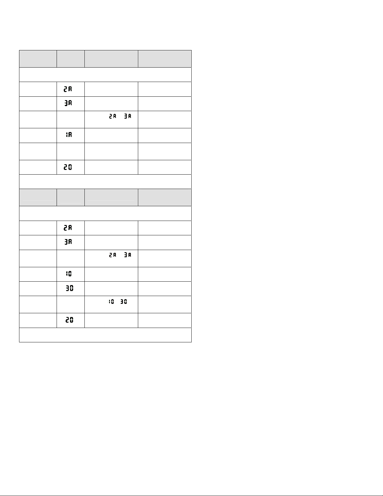
The last thing to understand about programming the time settings is that they represent the time between events in a sequence mode.
Mode 1 – Gear retraction event is as follows:
Command for gear retraction, Event 1 – Doors Open (2.A Time Delay applied), Event 2 – Door 2 opens (3.A Time Delay applied), Event
3 –Gear retracts (1.0 Time Delay applied), Event 4 – Door 2 Closes (3.0 Time Delay applied), Event 5 – Door 1 Closes (2.0 Time Delay
applied).
In the sequence described above the command for gear retraction (flipping the transmitter retract switch) will result in an immediate
opening of Door 1 (Event 1), and then the time delay that was entered for the Door 1 open sequence will be used to delay the opening
of Door 2 (Event 2), then the sum of the time delays that were entered for the Door 1 and Door 2 open sequence will be applied to
delay the retraction of the gear (Event 3).
Note: In the case of Mode 1 Door 2 is already open so the total delay for the Gear retraction is only the value entered for Door 1.
Continuing on from event 3, the time delay that was entered for the retract sequence will be applied to the trigger the closing of Door 2 (Event 4),
and finally the time delay that was entered for the Closing of door 2 will be applied to trigger (Event 5) Door 1 closes.
Formula View:
Event 1 + Event 2 = Total time for Event 3 to occur (Gear retraction)
Event 3 + Event 4 = Total time for Event 5 to occur (Door 1 Closure)
Hint: If you are not using Door #2 output you may choose to set program parameters 3.0and 3.Ato 0.0, as any time delay programmed in these
Door 2 delays will be added to the Door 1 delay times, by doing this you would need to set your total delay in the door 1 parameters.
Mode 1 timing sequence shown in table form:
Mode 1 Event 1 Event 2 Event 3 Event 4 Event 5
Switch to
Retract
Gear
No
delay
Door 1
Opens
.Time
Dela
y
Door 2
Already
Open in
Mode 1
.Time
Dela
y
Gear
retracts
.Time
Delay
Door 2
closes
.Time
Delay
Door 1
closes
__seconds No delay
applied __seconds __seconds
Mode 1 Event 1 Event 2 Event 3 Event 4 Event 5
Switch to
Extend
Gear
No
delay
Door 1
Opens
.Time
Dela
y
Door 2
Already
Open in
Mode 1
.Time
Dela
y
Gear
Extends
.Time
Delay
Door 2
Remains
Open
N/A Door 1
closes
__seconds No delay
applied __seconds
Page 8
For example, if you are programming a Mode 1 sequence where both doors open quickly, the gear retracts or extends after a delay of 2
seconds, and then door 1 closes quickly; the selected values would be entered as shown in the example Mode 1 table below.
Sample Mode 1 Table:
Mode 1 Menu
Item Desired Time
Set Value
From Table on
Page 7
Command Gear to Extend
Door 1
opens . 2 seconds 0.6
Door 2
opens .2 seconds 0.6
Time until
Gear
Extends
N/A (Sum of .& .)
4 seconds N/A
Gear
Extend .2 seconds 0.6
Door 2
Remains
Open
N/A N/A N/A
Door 1
closes . 1/3 second 0.1
End of Sequence
Mode 1 Menu
Item Desired Time
Set Value
From Table on
Page 7
Command Gear to Retract
Door 1
opens . 2 seconds Already Set Above
Door 2
Opens .2 seconds Already Set Above
Time until
Gear
Retracts
N/A (Sum of .& .)
4 seconds N/A
Gear
Retracts .2 seconds 0.6
Door 2
closes .1 second 0.3
Time until
Door 1
Closes
N/A (Sum of .& .)
3 seconds N/A
Door 1
closes .N/A N/A
End of Sequence
As before, each time you select a value, depress both buttons simultaneously to save the value.
Programming the sequencer becomes a little easier if you map out the values in a table before you begin programming. Blank tables have been
provided on the following page to copy and use for this purpose. The methods described above for Mode 1 apply for Modes 2 & 3.
Note: The unit remembers the last position it was in when powering down. It is important not to turn off power to the receiver until the
display indicates that the full sequence has completed and the air pressure in the system is once again displayed.

Page 9
Mode 1: Doors 1 and 2 open, landing gear extends, door 1 closes while door 2 remains open. On retraction, door 1 opens, landing
gear retracts and doors 1 and 2 both close.
Blank Mode 1 Table:
Mode 1 Menu
Item Desired Time
Set Value
From Table on
Page 7
Command Gear to Extend
Door 1
opens .
Door 2
opens .
Time until
Gear
Extends
Sum of .& .
Gear
Extend .
Door 2
Remains
Open
N/A N/A N/A
Door 1
closes .
End of Sequence
Mode 1 Menu
Item Desired Time
Set Value
From Table on
Page 7
Command Gear to Retract
Door 1
opens . Already Set Above
Door 2
Opens .Already Set Above
Time until
Gear
Retracts
Sum of .& .
Gear
Retracts .
Door 2
closes .
Time until
Door 1
Closes
Sum of .& .
Door 1
closes .N/A N/A
End of Sequence

Page 10
Mode 2: Doors 1 and 2 open, landing gear extends, doors 1 and 2 remain open. On retraction, the landing gear retracts, and doors 1
and 2 both close.
Blank Mode 2 Table:
Mode 2 Menu
Item Desired Time
Set Value
From Table on
Page 7
Command Gear to Extend
Door 1
opens .
Door 2
opens .
Time until
Gear
Extends
Sum of .& .
Gear
Extend .
Door 2
Remains
Open
N/A N/A N/A
Door 1
Remains
Open
N/A N/A N/A
End of Sequence
Mode 2 Menu
Item Desired Time
Set Value
From Table on
Page 7
Command Gear to Retract
Door 1
Already
Open . N/A N/A
Door 2
Already
Open
.N/A N/A
Time until
Gear
Retracts
On Command
Gear
Retracts .
Door 2
closes .
Time until
Door 2
Closes
Sum of .& .
Door 1
closes .N/A N/A
End of Sequence

Page 11
Mode 3: Doors 1 and 2 open, landing gear extends, and doors 1 and 2 close. On retraction, doors 1 and 2 open, the landing gear
retracts, doors 1 and 2 close.
Blank Mode 3 Table:
Mode 3 Menu
Item Desired Time
Set Value
From Table on
Page 7
Command Gear to Extend
Door 1
Opens .
Door 2
Opens .
Time until
Gear
Extends
Sum of .& .
Gear
Extend .
Door 2
Closes .
Time until
Door 1
Closes
Sum of .& .
Door 1
Closes N/A N/A N/A
End of Sequence
Mode 3 Menu
Item Desired Time
Set Value
From Table on
Page 7
Command Gear to Retract
Door 1
Opens . Already Set Above
Door 2
Opens .Already Set Above
Time until
Gear
Retracts
Sum of .& .
Gear
Retracts .
Door 2
Closes .
Time until
Door 1
Closes
Sum of .& .
Door 1
Closes N/A N/A N/A
End of Sequence
Page 12
Setting the Air Fail Safe Value
The ninth menu item is the air fail safe parameter, identified by .in the display. After pressing the “-“ button nine times enter
programming mode as before by holding the “+” button for two seconds after releasing the “-” button.
The typical fail safe pressure trip point is between 50 and 60 psi, using the “+” or “-” buttons, set the value from the table on page 2, for
example 50 psi (3,5 Bar) would be a value of 2.9. Depress both “+” & “-“ buttons to save and exit programming mode.
Pressurize your air system above the fail safe set point pressure.
Test the system by retracting the gear, and then gradually bleeding off air pressure, as the value on the display falls below the fail safe
value that was entered, the gear should extend.
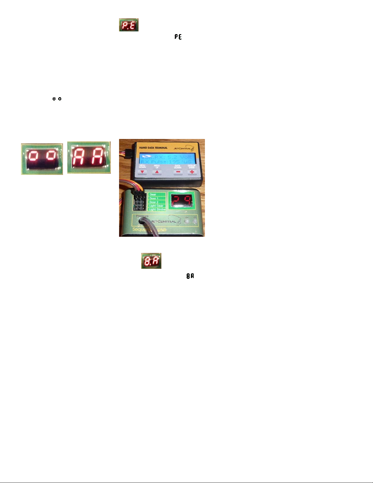
The following photos illustrates what happens during a pressure fail safe operation, the gear was set to the retracted position via the
transmitter( displayed), the failsafe value was set to 2.9 in the example programming step (i.e. approximately 50 PSI), the failsafe
triggered as air pressure was released (the AA display in the second photo) and commended a gear down as denoted by the 1952 uS
pulse width as shown in the third photo, the display reverted back to it default of reading air pressure in the third photo after a couple of
seconds, the transmitter switch remained in the gear up position.
Setting the Voltage Fail Safe Value
The tenth menu item is the voltage fail safe parameter, identified by .in the display. After pressing the “-“ button ten times enter
programming mode as before by holding the “+” button for two seconds after releasing the “-” button
Set the low voltage cut off value that you want to activate gear extension. Depress both “+” & “-“ buttons to save and exit programming
mode.
Caution: Input voltage is sensed through the receiver connection, if a voltage regulator is used for the system power then the
sequencer will not indicate the true battery charge condition and therefore the low voltage fail safe should not be depended upon for
indication of low battery condition.
Light Outputs
The strobe light output is set for a 50/50 duty cycle and switches between 0 volts and the applied input voltage, the maximum current
drive is xx mA.
The landing light output switches between 0 volts and the applied input voltage with the gear extended, the maximum current drive is xx
mA.
Congratulations and enjoy your purchase. Should you experience problems with the unit, please
contact Jet Central for assistance.
Table of contents


