Jet AHR-50 User manual

OWNER'S MANUAL
AHR-50 Auto Rewind Hose Reel
JET EQUIPMENT & TOOLS, INC. P.O. BOX 1349 Phone:253-351-6000
AWMH Company Auburn, WA98071-1349 Fax: 1-800-274-6840
www.jettools.com e-mail jet@jettools.com M-426238 09/01

2
This manual has been prepared for the owner and operators of a JET AHR-50 Hose Reel. Its purpose,
aside from machine operation, is to promote safety through the use of accepted correct operating and
maintenance procedures. Completely read the safety and maintenance instructions before operating or
servicing the hose reel. To obtain maximum life and efficiency from your hose reel, and to aid in using
the hose reel safely, read this manual thoroughly and follow instructions carefully.
Warranty & Service
The JET Group warrants every product it sells. If one of our tools needs service or repair, one of our
Authorized Repair Stations located throughout the United States can give you quick service.
In most cases, any one of these JET Group Repair Stations can authorize warranty repair, assist you in
obtaining parts, or perform routine maintenance and major repair on your JET, Performax or Powermatic
tools.
For the name of an Authorized Repair Station in your area, please call 1-800-274-6848.
More Information
Remember, the JET Group is consistently adding new products to the line. For complete,
up-to-date product information, check with your local JET Group distributor.
JET Group Warranty
The JET Group (including Performax and Powermatic brands) makes every effort to assure that its
products meet high quality and durability standards and warrants to the original retail consumer/purchaser
of our products that each product be free from defects in materials and workmanship as follow: 1 YEAR
LIMITED WARRANTY ON ALL PRODUCTS UNLESS SPECIFIED OTHERWISE. This Warranty does
not apply to defects due directly or indirectly to misuse, abuse, negligence or accidents, normal
wear-and-tear, repair or alterations outside our facilities, or to a lack of maintenance.
THE JET GROUP LIMITS ALL IMPLIED WARRANTIES TO THE PERIOD SPECIFIED ABOVE, FROM
THE DATE THE PRODUCT WAS PURCHASED AT RETAIL. EXCEPT AS STATED HEREIN, ANY
IMPLIED WARRANTIES OR MERCHANTIBILITY AND FITNESS ARE EXCLUDED. SOME STATES
DO NOT ALLOW LIMITATIONS ON HOW LONG THE IMPLIED WARRANTY LASTS, SO THE ABOVE
LIMITATION MAY NOT APPLY TO YOU. THE JET GROUP SHALL IN NO EVENT BE LIABLE FOR
DEATH, INJURIES TO PERSONS OR PROPERTY, OR FOR INCIDENTAL, CONTINGENT, SPECIAL,
OR CONSEQUENTIAL DAMAGES ARISING FROM THE USE OF OUR PRODUCTS. SOME STATES
DO NOT ALLOW THE EXLUSION OR LIMITATION OF INCIDENTAL OR CONSEQUENTIAL DAMAGES,
SO THE ABOVE LIMITATION OR EXCLUSION MAY NOT APPLY TO YOU.
To take advantage of this warranty, the product or part must be returned for examination, postage prepaid,
to an Authorized Repair Station designated by our office. Proof of purchase date and an explanation of
the complaint must accompany the merchandise. If our inspection discloses a defect, we will either
repair or replace the product, or refund the purchase price if we cannot readily and quickly provide a
repair or replacement, if you are willing to accept a refund. We will return repaired product or
replacement at JET’S expense, but if it is determined there is no defect, or that the defect resulted from
causes not within the scope of JET’S warranty, then the user must bear the cost of storing and returning
the product. This warranty gives you specific legal rights; you may also have other rights which vary
fromstatetostate.
The JET Group sells through distributors only. Members of the JET Group reserve the right to effect at
any time, without prior notice, those alterations to parts, fittings, and accessory equipment which they may
deem necessary for any reason whatsoever.

3
Specifications AHR-50
Stock #.......................................................................................................................................... 426238
Hose Type....................................................................................................................Reinforced Rubber
Hose Size (ID x L)....................................................................................................................... 3/8” x 50’
Working Pressure...........................................................................................................................300 psi
Hose Inlet Size ............................................................................................................................3/8” NPT
Hose Outlet Size..........................................................................................................................1/4" NPT
Overall Dimensions (LxWxH)....................................................................................................21”x7”x19”
Net Weight (lbs).....................................................................................................................................47
Table of Contents Page Number
Warranty..................................................................................................................................................2
Specifications ..........................................................................................................................................3
Table of Contents ....................................................................................................................................3
Hose Reel Safety Precautions .................................................................................................................4
Installation of Reel...................................................................................................................................4
Operation.................................................................................................................................................5
Adjustment of Spring Tension..................................................................................................................5
Replacement of Swivel Seal.....................................................................................................................5
Replacement of Hose ..............................................................................................................................5
Spring Canister........................................................................................................................................5
Troubleshooting.......................................................................................................................................6
Parts Breakdown .....................................................................................................................................7
Parts List ..............................................................................................................................................8-9
Test Certificate ......................................................................................................................................10
Mounting Template................................................................................................................................11
The specifications in this manual are given as general information and are not binding. JET Equipment
and Tools reserves the right to effect, at any time and without prior notice, changes or alterations to parts,
fittings, and accessory equipment deemed necessary for any reason whatsoever.

4
Hose Reel Safety Precautions
WARNING
Exposure of skin directly to pressurized air,
or fluid could result in severe bodily injury.
1. Make sure incoming line pressure does not
exceed rated operating pressure for your
model hose reel.
2. Use proper eye protection when assembling
and using the hose reel.
3. Assemble the hose reel on a clean
workbench.
4. Use soap and water when checking for
leaks.
5. Keep children away from the work area.
Installation of Reel
For overhead ceiling mounting: Install reel
between ten and fifteen feet above the floor.
You will need to purchase appropriate hardware
for mounting your new reel (four 7/16" or M12
bolts, washers and nuts or four masonry bolts,
or similar depending on installation).
1. The reel base has four 1/2” (or 12.7mm)
drilled holes for mounting on a suitable flat
surface.
2. The reel is supplied with a hose guide roller
bracket. The bracket position may be
changed depending on the reel mounting
position. Figure 1 shows “Typical Mounting
Positions”. If bracket position needs to be
changed, do the following:
• Pull out some hose and let reel latch.
See Operation Section: “To Latch,” “To
Unlatch,” page 4.
• Remove the bolts that attach the guide
roller bracket to the support post.
• Rotate guide roller bracket to correct
position, replace bolts and tighten.
3. Using the four holes in the base, mount the
reel in the desired location. Be sure to use
appropriate hardware and tighten securely.
4. Flush hose with air or water prior to
connecting to source. Apply Teflon tape or
pipe sealant to supply line threads, attach to
reel inlet and tighten. The other end of
incoming line can now be connected to
desired supply source.
Note: A swivel connector and flexible inlet
hose are required for supply line or warranty is
void.
5. Flush some product through the system and
reel prior to connecting outlet nozzle to tool.
Apply Teflon tape or pipe sealant to outlet
fitting on reel hose, and then attach to
desired tool, or nozzle. Check connection
for leakage using soapy water.
6. If hose stopper adjustment is required, pull
hose from reel and allow latching at desired
length. Loosen stopper screws and slide
stopper to a position close to the hose guide.
Tighten stopper screws, and unlatch the
reel.
Fig. 1

5
Operation
1. Check reel for correct operation by slowly
pulling out the hose. A “clicking” noise will
be heard every half revolution of the drum.
2. To latch: the reel, pull out the hose and
allow it to retract after hearing the first,
second, or third “click”.
3. To unlatch: slowly pull out the hose until the
“clicking” noise stops, and then let the hose
retract until the hose stop rests against the
hose guide.
WARNING
Do not allow hose to retract without
restraining recoil speed. Never let go of the
hose when rewinding. Failure to comply
may result in severe injury.
4. Periodically check the hose condition for
wear or damage, and check the swivel fitting
for leakage. Replace any worn, damaged,
or leaking parts.
Adjustment of Spring Tension
1. Pull out approximately 6 feet, or 2 meters of
hose and allow the drum to latch.
2. Remove hose stopper from hose, and feed
hose back through guide.
3. Wrap the pulled hose one time around the
drum to increase tension or un-wrap hose
one time from drum to decrease tension.
4. Re-insert hose through guide, and install
stopper onto hose end.
5. Pull hose from reel, and check tension.
Adjust stopper if necessary.
Replacement of Swivel Seal
1. Turn off and disconnect supply line from
swivel inlet.
2. Remove swivel assembly from reel axle.
3. Remove retainer clip from swivel, and take
apart.
Note: You may want to remove swivel from
reel hose end, but this in not necessary unless a
new swivel is being installed.
4. Replace the seals and reassemble swivel.
5. Use Teflon tape, or thread sealant on swivel
thread fitting, reconnect the swivel thread
fitting with axle.
6. Re-connect inlet supply line and use soapy
water to check for leaks.
Replacement of Hose
1. Turn off supply to reel and drain.
2. Pull out all the old hose and lock the reel in
this position.
WARNING
Make sure reel drum is securely locked and
cannot rotate back. Failure to comply may
result in severe injury.
3. Remove two hose clamps from hose.
4. Carefully disconnect hose from swivel joint
on side of reel, or male fitting in axle center
and remove old hose.
5. Use the hose guard and hose stop from the
old hose and place in the same position on
the new hose.
6. Feed new hose through guide and opening
in drum, and connect to swivel. Use thread
sealant or Teflon tape on the threads.
7. Re-install two hose clamps, on inside and
outside of drum flange.
8. Carefully release the drum latch, and slowly
allow the hose to wind onto the reel.
Note: Final spring adjustment is accomplished
by adding, or removing wraps of hose around
the drum. See “Adjustment of Spring Tension.”
Spring Canister
If the rewind spring fails for any reason: For
safety reasons, the manufacturer strongly
recommends the replacement of the spring
canister be carried out by a JET Authorized
Repair Station.

6
Troubleshooting
Trouble Cause Remedy
Hose will not fully
retract
1. Outlet nozzle, gun or tool is too
heavy.
2. Spring is fatigued.
3. Replacement hose is too long.
1. Add spring tension. See
"Adjustment of Spring Tension.”
2. Add spring tension. See
"Adjustment of Spring Tension.”
Replace spring canister if
required.
3. Call local Distributor for correct
specified hose length.
Hose will not retract at
all Spring has lost all tension or has
possibly broken.
1. Reinstall spring tension
2. Replace spring canister. Have a
JET Authorized Repair Station
replace the spring canister.
Reel will not latch
1. Incorrect operation.
2. Dog spring or locking cam is
broken or worn.
1. Reel latches on first, second,
third or fourth "click". After forth
"click" it automatically rewinds.
2. Replace dog spring or locking
cam.
Fluid leaks from swivel Swivel seals are worn. Replace swivel seals. See
"Replacement of Swivel Seal.” Be
sure leak is not at hose fitting.

7
Parts Breakdown for JET AHR-50

8
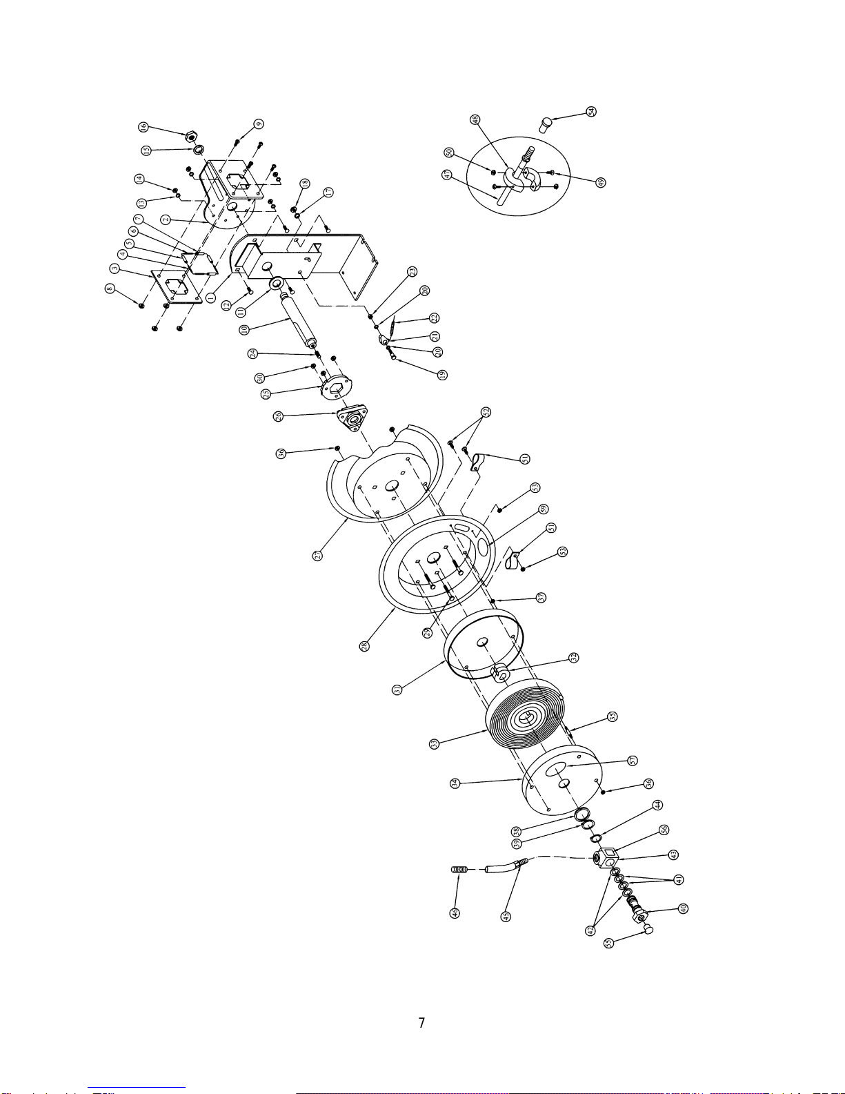
Parts List for the AHR-50
Index Part
No. No. Description Size Qty.
1..........AHR50-1...................................Base ..................................................... ...................................1
2..........AHR50-2...................................Support Plate........................................ ...................................1
3..........AHR50-3...................................Guide Plate........................................... ...................................1
4..........AHR50-4...................................RollerAxle (long)................................... ...................................2
5..........AHR50-5...................................Roller (long) .......................................... ...................................2
6..........AHR50-6...................................RollerAxle (short).................................. ...................................2
7..........AHR50-7...................................Roller (short)......................................... ...................................2
8..........AHR50-8...................................Nyloc Nut ** ......................................... M5..............................4
9..........AHR50-9...................................Pan Head Machine Screw ** ................ M5x10........................4
10........AHR50-10.................................Shaft..................................................... ...................................1
11 ........AHR50-11 .................................Washer ** ............................................ ...................................1
12........AHR50-12.................................Carriage Bolt ** .................................... M8x20........................4
13........AHR50-13.................................Lock Washer ** .................................... M8..............................4
14........AHR50-14.................................Nyloc Nut ** ......................................... M8..............................4
15........AHR50-15.................................Lock Washer ** .................................... M16............................1
16........AHR50-16.................................Hex Nut ** ........................................... M16............................1
17........AHR50-17.................................Lock Washer ** .................................... M10............................1
18........AHR50-18.................................Hex Nut ** ........................................... M10............................1
19........AHR50-19.................................Bolt ....................................................... M10x43 ......................1
20........AHR50-20.................................Bushing................................................. ∅13x∅19x1.6.............2
21........AHR50-21.................................Locking Cam......................................... ...................................1
22........AHR50-22.................................Dog Spring............................................ ...................................1
23........AHR50-23.................................Bushing ** ........................................... ∅13x∅19x10..............1
24........AHR50-24.................................Screw ** .............................................. M10x30 ......................1
25........AHR50-25.................................Locking Ring......................................... ...................................1
26........AHR50-26.................................Assembly Hub Bearing.......................... ...................................1
27........AHR50-27.................................Drum..................................................... ...................................1
28........AHR50-28.................................Drum..................................................... ...................................1
29........AHR50-29.................................Bolt ** .................................................. M6x37........................3
30........AHR50-30.................................Nyloc Nut ** ......................................... M6..............................3
31........ .................................................Spring Drum.......................................... ...................................1
............AHR50-31A...............................Spring Drum Assembly (includes: 31, 32, 33, 34, 35, 36, 37, 57)..
32........ .................................................Spring Core........................................... ...................................1
33........ .................................................Spring................................................... ...................................1
34........ .................................................Spring Drum.......................................... ...................................1
35........ .................................................Bolt ....................................................... M6x56........................4
36........AHR50-36.................................Nyloc Nut ** ......................................... M6..............................8
37........AHR50-37.................................Nut ** .................................................. M6..............................4
38........AHR50-38.................................Washer ** ............................................ ∅19.5x∅40x2.............1
39........AHR50-39.................................Retaining Ring ** ................................. 19...............................1
40........AHR50-40.................................Swivel Spool.......................................... ...................................1
41........AHR50-41.................................O-Ring.................................................. ASM568-210...............2
42........AHR50-42.................................Retainer................................................ 8-210..........................2
43........AHR50-43.................................Swivel Body.......................................... ...................................1
............AHR50-43A...............................Swivel Assembly (includes: 38, 39, 40, 41, 42, 43, 44, 56)...........
44........AHR50-44.................................Retaining Ring ** ................................. 25...............................1
45........AHR50-45.................................Fitting.................................................... ...................................2
46........AHR50-46.................................Hose Protection Spring.......................... ...................................1
47........AHR50-47.................................Replacement Air Hose........................... 3/8” x 50’.....................1
48........AHR50-48.................................Hose Stop............................................. ...................................2
49........AHR50-49.................................Pan Head Machine Screw ** ................ M6x40........................2
50........AHR50-50.................................Hex Nut ** ........................................... M6..............................2
51........AHR50-51.................................Clamp................................................... ...................................2
52........AHR50-52.................................Pan Head Machine Screw ** ................ M5x12........................2

9
Index Part
No. No. Description Size Qty.
53........AHR50-53.................................Nyloc Nut ** ......................................... M5..............................2
54........AHR50-54.................................Plastic Cover......................................... ...................................1
55........AHR50-55.................................Plastic Plug........................................... ...................................1
56........AHR50-56.................................Swivel Label * ...................................... ...................................1
57........AHR50-57.................................Spring Drum Label * ............................ ...................................1
59........AHR50-59.................................Arrow Label * ....................................... ...................................1
............AHR50-ID .................................JET I.D. Label (not shown) .................... ...................................1
............AHR50-LK.................................*Label Kit (includes: 56, 57, 59)............. .....................................
............AHR50-HK................................**Hardware Kit (includes: 8, 9, 11, 12, 13, 14, 15, 16, 17, 18, 23,.
............ .................................................24, 29, 30, 36, 37, 38, 39, 44, 49, 50, 52, 53)...............................

10
JET EQUIPMENT & TOOLS, INC. P.O. BOX 1349 Phone: 253-351-6000
AWMH Company Auburn, WA98071-1349 Fax: 1-800-274-6840
www.jettools.com

11
Mounting Template
Table of contents
Other Jet Accessories manuals