Jet EHPT-2045 User manual

OWNER'S MANUAL
EHPT Series Electric High Lift Pallet Trucks
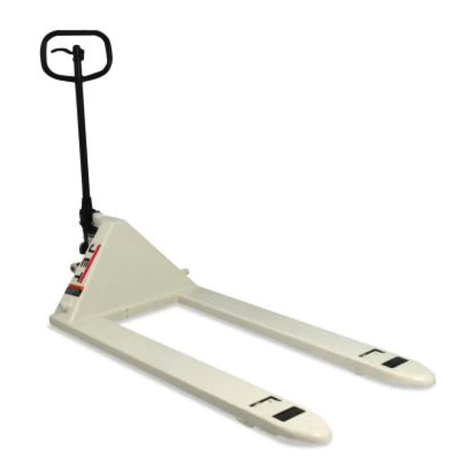
Model EHPT-2745 shown
JET P.O. BOX 1349 Phone: 253-351-6000
WMH Tool Group Auburn, WA 98071-1349 Fax: 1-800-274-6840
www.jettools.com e-mail jet@wmhtoolgroup.com M-140089 1/03

2
This manual has been prepared for the owner and operators of a JET EHPT series Electric High Lift
Pallet Truck. Its purpose, aside from truck operation, is to promote safety through the use of accepted
correct operating and maintenance procedures. Completely read the safety and maintenance
instructions before operating or servicing the truck. To obtain maximum life and efficiency from your
pallet truck, and to aid in using the truck safely, read this manual thoroughly and follow instructions
carefully.
Warranty & Service
WMH Tool Group warrants every product it sells. If one of our tools needs service or repair, one of our
Authorized Repair Stations located throughout the United States can give you quick service.
In most cases, any one of these WMH Tool Group Repair Stations can authorize warranty repair, assist
you in obtaining parts, or perform routine maintenance and major repair on your JET, Performax,
Powermatic or Wilton tools.
For the name of an Authorized Repair Station in your area, call 1-800-274-6848.
More Information
WMH Tool Group is consistently adding new products to the line. For complete, up-to-date product
information, check with your local WMH Tool Group distributor or visit wmhtoolgroup.com.
Limited Warranty
WMH Tool Group (including JET, Performax, Powermatic and Wilton brands) makes every effort to
assure that its products meet high quality and durability standards and warrants to the original retail
consumer/purchaser of our products that each product be free from defects in materials and
workmanship as follows: 1 YEAR LIMITED WARRANTY ON ALL PRODUCTS UNLESS SPECIFIED
OTHERWISE. This warranty does not apply to defects due directly or indirectly to misuse, abuse,
negligence or accidents, normal wear-and-tear, repair or alterations outside our facilities, or to a lack of
maintenance.
WMH TOOL GROUP LIMITS ALL IMPLIED WARRANTIES TO THE PERIOD SPECIFIED ABOVE,
FROM THE DATE THE PRODUCT WAS PURCHASED AT RETAIL. EXCEPTAS STATED HEREIN,
ANY IMPLIED WARRANTIES OR MERCHANTIBILITY AND FITNESS ARE EXCLUDED. SOME
STATES DO NOT ALLOW LIMITATIONS ON HOW LONG THE IMPLIED WARRANTY LASTS, SO THE
ABOVE LIMITATION MAY NOT APPLY TO YOU. WMH TOOL GROUP SHALL IN NO EVENT BE
LIABLE FOR DEATH, INJURIES TO PERSONS OR PROPERTY, OR FOR INCIDENTAL,
CONTINGENT, SPECIAL, OR CONSEQUENTIAL DAMAGES ARISING FROM THE USE OF OUR
PRODUCTS. SOME STATES DO NOT ALLOW THE EXCLUSION OR LIMITATION OF INCIDENTAL
OR CONSEQUENTIAL DAMAGES, SO THE ABOVE LIMITATION OR EXCLUSION MAY NOT APPLY
TO YOU.
To take advantage of this warranty, the product or part must be returned for examination, postage
prepaid, to an Authorized Repair Station designated by our office. Proof of purchase date and an
explanation of the complaint must accompany the merchandise. If our inspection discloses a defect,
WMH Tool Group will either repair or replace the product, or refund the purchase price if we cannot
readily and quickly provide a repair or replacement, if you are willing to accept a refund. WMH Tool
Group will return repaired product or replacement at our expense, but if it is determined there is no
defect, or that the defect resulted from causes not within the scope of our warranty, then the user must
bear the cost of storing and returning the product. This warranty gives you specific legal rights; you may
also have other rights, which vary from state to state.
WMH Tool Group sells through distributors only. WMH Tool Group reserves the right to effect at any
time, without prior notice, those alterations to parts, fittings, and accessory equipment which they may
deem necessary for any reason whatsoever.

3
Table of Contents Page
Warranty .................................................................................................................................... 2
Specifications............................................................................................................................. 3
Introduction................................................................................................................................. 3
Assembly and Adjustment .......................................................................................................... 4
Safety Precautions ..................................................................................................................... 4
Operation ................................................................................................................................ 4-5
Maintenance............................................................................................................................... 5
Trouble Shooting........................................................................................................................ 6
Parts Lists and Breakdowns:
Fork Assembly...................................................................................................................... 7-8
Pump Assembly.................................................................................................................. 9-10
Electrical Controls Assembly ............................................................................................ 11-12
Electrical Schematic................................................................................................................. 13
Specifications
Model Number..........................................................EHPT-2045...............................EHPT-2745
Stock Number..................................................................140089......................................140090
Capacity (lbs) .....................................................................2,200.........................................2,200
Min./Max. Fork Height (in) ......................................3-1/4 / 31-1/2.............................3-1/4 / 31-1/2
Fork Width (in).......................................................................... 7............................................... 7
Overall Fork Dimensions L x W (in).......................20-15/32 x 45................................26-3/4 x 45
Battery Type..........................................................DC 12V 66Ah............................DC 12V 66Ah
Battery Charger Input ..................................................115V 1Ph..................................115V 1Ph
Battery Charger Output..................................................12V 10A....................................12V 10A
Full Load Full Lift Cycle (seconds).......................................... 18............................................. 18
Full Charge Lifting Cycles....................................................... 65............................................. 65
Load Wheel OD x W (in) .....................................................3 x 2..........................................3 x 2
Steer Wheel OD x W (in).....................................................6 x 2..........................................6 x 2
Overall Dimensions L x W x H (in).....................63 x 20-7/8 x 50...................... 63 x 27-3/16 x 50
Net Weight (lbs).....................................................................308............................................321
Introduction
Congratulations on your purchase of a JET Electric High Lift Pallet Truck.
This electric high lift pallet truck is designed to reduce lifting injuries and increase productivity by lifting,
lowering, and transporting open pallets and skids only with ease. It does not work with closed pallets
unless the pallet is placed on top of forks. An optional steel platform converts the electric high lift pallet
truck to a mobile workstation.
Notable features include a Fenner/Haldex Barnes mini-hydraulic pump system with built-in automatic
overload protection. Power is provided by AC Delco maintenance-free 12V battery with 585 cold
cranking amps. The heavy-duty welded steel frame features a powder coat finish to inhibit rust. With
regular maintenance, your electric high lift pallet truck will provide years of dependable service.
The specifications in this manual are given as general information and are not binding. WMH Tool Group
reserves the right to effect, at any time and without prior notice, changes or alterations to parts,
fittings, and accessory equipment deemed necessary for any reason whatsoever.

4
Assembly & Adjustment
(refer to exploded views)
1. Remove packing material carefully and
inspect for any damage during shipment.
2. Insert handle (102) into the socket of
cylinder (160); lock it with pin (108) and two
screws (109). Swing the handle up and
down to see if it moves freely. Attach
tension spring (105).
3. Open electrical control case by removing
thumb screws (256) and cover (255). Insert
up/down switch wire and plug (184) hanging
down from handle (102) into socket (221) in
the case. Insert two 5 Amp fuses (277) into
two sockets F1/F2.
4. Check the electrical device and elements in
the case to make sure none are loose or
damaged. Tighten any elements if loose.
5. Check high pressure oil pipe (282) in the
hydraulic system to confirm it is not loose.
Tighten if loose. Open cover (217) to check
hydraulic level.
6. Push “Up” button (197) on top of handle
(102) intermittently to lift the fork. Push and
hold the “Up” button to lift the forks to their
highest position. Then push and hold the
“Down” button (197) to lower the forks to
their lowest position. Repeat this procedure
3 to 4 times with full up and down travel to
release any possible air in the hydraulic
system and to confirm all components are
functioning correctly.
7. Close cover (255).
Safety Precautions
1. Read and understand owner's manual
before operation.
2. Do not exceed rated capacity.
3. Before using pallet truck, lift and lower the
forks several times with no load to release
any air that may be trapped in the hydraulic
system.
4. Never allow anyone to ride on the pallet
truck.
5. Operate on smooth, level finished floors
only. Automatic brake system will not
engage properly if forks are raised on
uneven floor. Do not use on slope.
6. Always keep hands and feet clear from all
moving parts including forks, legs, piston
rod (406) and mid-cylinder (413).
7. Always secure load equally on the forks
nearest the bulkhead before lifting or
lowering. Do not lift load with fork tip only.
8. Automatic overload safety valve will open if
pallet truck is overloaded. If overloaded, do
not push the "Up" button as this will reduce
the life of the pump station.
9. When transporting loads, always keep
people clear from pallet truck and transport
in the lowered position only.
WARNING
Failure to comply with all of these safety
precautions may result in loss of load,
damage to pallet truck, personal injury
and/or property damage.
Operation
The pallet truck is designed for use with open
style pallets or skids only. Closed style pallets
must be placed on top of forks prior to use.
The handle is designed to pull and steer the
pallet truck only. Do not use the handle as a
leverage tool.
WARNING
Do not attempt to move pallet truck with
forks in raised position. Lower forks
completely before moving pallet truck.
To raise forks, press the “Up” button in the
center of the handle, hold until desired height is
achieved, then release. The automatic brake
system featuring two axles (7) will engage the
floor to prevent movement.
To lower forks, press the “Down” button, hold
until desired height is achieved, then release.
The forks can be stopped at any position and
will hold firmly in place.
The pump assembly features an overload safety
valve. When the pallet truck lifts beyond its
maximum capacity, only the mid-cylinder (413)
will extend out fully; the piston rod (406) cannot
extend.
If pallet truck is overloaded, the mid-cylinder
(413) only will rise. The pison rod (406) will not.
Avoid pushing the "Up" button when overloaded
to prevent any damage to the pump station.

5
If the lifting speed becomes too slow, the battery
needs to be charged. Proceed as follows:
1. Lower forks, remove screws (32) and metal
cover (30).
2. Plug charger power cable (271) into a
standard 115V single phase wall socket.
3. Connect charger outlet cable to socket (225)
located in the electrical control case.
4. Normal charge time for battery is 4 to 5
hours. A yellow light on the voltage meter
(283) indicates battery is charging.
5. Full charge may take up to 16 hours if
battery is completely dead.
6. Do not operate while charging the battery.
Maintenance
After lowering forks, check hydraulic fluid level
visually in plastic tank located under pump
station assembly (220).
Proper hydraulic fluid level is approximately 1"
from bottomof tank. If hydraulic fluid level is
less than 1", add high quality hydraulic fluid or
hydraulic jack oil.

6
Troubleshooting for EHPT Pallet Truck
Trouble Cause Remedy
(with parts list reference number)
Forks do not lift when
pushing “Up” button.
1. Control switch malfunction.
2. Fuse blown.
3. Magnetic switch malfunction.
4. Hydraulic fluid level low.
1. Check switch (197).
2. Replace fuse (277).
3. Check magnetic switch (224).
4. Lower forks fully and add
hydraulic fluid.
Forks do not lower
when pushing “Down”
button.
1. Control switch malfunction.
2. Fuse blown.
3. Magnetic switch malfunction.
4. Object is blocking fork
movement.
1. Check switch (197).
2. Replace fuse (277).
3. Check magnetic switch (224).
4. Clear object from fork or leg.
Forks do not lift to
highest position. 1. Hydraulic oil level low. 1. Lower forks fully and add
hydraulic fluid.
Pump station motor
won’t start.
1. Motor malfunction.
2. Terminals and wire connectors
are loose.
3. Battery depleted.
1. Check motor brushes.
2. Check terminals and wire
connectors.
3. Charge battery.
Battery is weak.
1. Not enough time on battery
charger.
2. Battery voltage depleted.
1. Charge battery 4 to 5 hours.
2. Test battery to ensure it can hold
a charge. Replace if necessary
(local purchase).
Oil leaking from piston
rod & mid-cylinder. 1. Oil seals worn or broken. 1. Replace oil seals.
Unsteady load when
EHPT is in its highest
position.
1. Ground not flat or even.
2. Centrifugal axle doesn’t reach
the floor.
1. Work on flat/even ground.
2. Adjust axle (7) so it touches the
floor.

7
Parts Breakdown
EHPT Series Fork Assembly

8
Parts List
EHPT Series Fork Assembly
Index Part
No. No. Description Size Quantity
1..........EHPT-1........................ Fork Frame............................................ .................................. 1
2..........EHPT-2........................Slotted Set Screw w/ Cone Point ...........M8 x 30...................... 2
3..........TS-1541021................. Lock Nut................................................M8 ............................. 2
4..........EHPT-4........................Pump Assembly..................................... .................................. 1
5..........EHPT-5........................Hold Yoke.............................................. .................................. 1
6..........EHPT-6........................ Wheel Yoke........................................... .................................. 1
7..........EHPT-7........................ Centrifugal Axle..................................... .................................. 2
8..........EHPT-8........................ Spacer................................................... .................................. 2
9..........EHPT-9........................ Steer Wheel ..........................................6” x 2”........................ 2
10........EHPT-10...................... Snap Ring..............................................20 mm ....................... 8
11........EHPT-11...................... Shaft Pin ...............................................Ø22 x 51mm............... 2
12........EHPT-12...................... Snap Ring..............................................22 mm ..................... 12
13........EHPT-13...................... Bushing................................................. .................................. 2
14........EHPT-14...................... Outside Leg........................................... .................................. 2
15........EHPT-15...................... Inside Leg.............................................. .................................. 1
16........EHPT-16...................... Bushing................................................. .................................. 2
17........EHPT-17...................... Shaft Pin ...............................................Ø22 x 86 mm.............. 2
18........EHPT-18...................... Bushing.................................................Ø32 x 9 mm................ 2
19........TS-154010................... Hex Nut.................................................M16............................ 2
20........TS-2360221................. Flat Washer...........................................M22............................ 8
21........BB-6204VV.................. Ball Bearing...........................................6204VV...................... 8
22........EHPT-22...................... Load Wheel...........................................3” x 2” ........................ 2
23........EHPT-23...................... Wheel Axle............................................ .................................. 2
24........EHPT-24...................... Roller..................................................... .................................. 4
25........EHPT-25...................... Bushing................................................. .................................. 2
26........TS-155010................... Flat Washer...........................................M16............................ 4
27........TS-155110................... Lock Washer .........................................M16............................ 2
28........TS-2340161................. Lock Nut................................................M16............................ 2
29........TS-1524011................. Flat Point Socket Set Screw..................M8 x 8........................ 3
30........EHPT-30...................... Cover .................................................... .................................. 1
31........EHPT-31...................... Back Cover............................................ .................................. 1
32........TS-1534052................. Philips Pan Head Screw ........................M6 x 16...................... 8
............EHPT-HL ..................... Hazard Label for Legs(not shown)..........17” x 1-3/4” ................ 4
............EHPT-ID...................... I.D. Label (not shown)............................4” x 2-3/8”.................. 1
............EHPT-LWL .................. Loading Warning Label (not shown).......4-3/8” x 1-9/16” .......... 1
............EHPT-CL ..................... Capacity Label (not shown)....................2-3/4” x 1-9/16” .......... 1

9
Parts Breakdown
EHPT Series Pump Assembly

10
Parts List
EHPT Series Pump Assembly
Index Part
No. No. Description Size Quantity
97........EHPT-97...................... Handle................................................... .................................. 1
98........EHPT-98...................... Handle Cover ........................................ .................................. 1
99........EHPT-99...................... Phillips Flat Head Wood Screw..............M5 x 35...................... 4
100......EHPT-100.................... Phillips Pan Head Machine Screw .........M6 x 8........................ 4
102......EHPT-102.................... Handle Tube.......................................... .................................. 1
105......EHPT-105.................... Air Spring ..............................................Ø22 x 240 mm............ 1
108......EHPT-108.................... Pin for Handle........................................Ø12 x 95 mm.............. 1
109......TS-1540071................. Hex Nut.................................................M10............................ 2
110......EHPT-110.................... Adjusting Screw.....................................M20 x 1.15 x 25......... 1
111......EHPT-111.................... Snap Ring..............................................M8 ............................. 4
112......EHPT-112.................... Sleeve................................................... ..................................2
113......EHPT-113.................... Air Spring Pin ........................................Ø10 x 81 mm.............. 1
114......EHPT-114.................... Air Spring Support Pin...........................Ø10 x 29 mm.............. 1
136......EHPT-136.................... Scraper Ring *....................................... .................................. 1
137......EHPT-137.................... O-Ring * ................................................42.5 x 3.55 mm.......... 1
138......EHPT-138.................... Gasket * ................................................52 x 40 x 10 mm........ 1
153......EHPT-153.................... O-Ring * ................................................50.5 x 2.4 mm............ 1
160......EHPT-160.................... Pump Housing....................................... .................................. 1
161......BB-51112..................... Thrust Bearing.......................................51112......................... 1
162......SB-19........................... Steel Ball...............................................19 mm ....................... 1
163......EHPT-163.................... Snap Ring..............................................25 mm ....................... 1
164......EHPT-164.................... Backup Piston Washer ..........................Ø35 x Ø25 x 2 mm...... 1
184......EHPT-184.................... Switch Wire & Plug................................ .................................. 1
190......EHPT-190.................... Copper Piston........................................ .................................. 1
191......EHPT-191.................... Backup Washer.....................................Ø43.8 x 2.5 mm.......... 1
192......EHPT-192.................... Snap Ring..............................................Ø25 mm ..................... 1
195......TS-2360121................. Flat Washer * ........................................M12............................ 1
197......EHPT-197.................... Up-Down Switch.................................... .................................. 1
198......EHPT-198.................... O-Ring * ................................................53 x 2.65 mm............. 2
200......EHPT-200.................... Cylinder................................................. .................................. 1
201......EHPT-201.................... Back-Up Ring *...................................... .................................. 1
400......EHPT-400.................... Bronze Bushing..................................... .................................. 1
401......EHPT-401.................... Backup Ring*......................................... .................................. 1
402......EHPT-402.................... Y-Ring *................................................. ..................................1
403......EHPT-403.................... Bushing................................................. .................................. 1
404......EHPT-404.................... Snap Ring.............................................. .................................. 1
405......EHPT-405.................... Bushing................................................. .................................. 1
406......EHPT-406.................... Piston Rod............................................. .................................. 1
407......EHPT-407.................... O-Ring * ................................................20.6 x 2.4 mm............ 1
408......EHPT-408.................... Piston.................................................... .................................. 1
409......EHPT-409.................... Washer for Piston..................................Ø30 x Ø14.2 x 4.......... 1
410......TS-236114................... Lock Washer .........................................M14............................ 1
411......TS-2212251................. Hex Cap Screw......................................M14 x 25.................... 1
412......EHPT-412.................... Cylinder Head........................................ .................................. 1
413......EHPT-413.................... Cylinder................................................. .................................. 1
............EHPT-RK..................... Pump Repair Kit (contains items with *). .................................. 1
............EHPT-UDL................... Up-Down Switch Label (not shown)........1-1/2” x 3/4” ............... 1

11
Parts Breakdown
EHPT Series Electrical Controls Assembly

12
Parts List
EHPT Series Electrical Control Assembly
Index Part
No. No. Description Size Quantity
202......EHPT-202.................... Battery Terminal (+)............................... .................................. 1
203......EHPT-203.................... Battery Terminal (-) ............................... .................................. 1
204......EHPT-204.................... Terminal................................................ .................................. 2
205......TS-1551071................. Lock Washer .........................................M10............................ 2
206......EHPT-206.................... Hex Head Bolt.......................................3/8-16 x 5/8................ 2
207......EHPT-207.................... Electrical Control Case.......................... .................................. 1
220......EHPT-220.................... Pump Station Assembly......................... .................................. 1
221......EHPT-221.................... Switch Socket........................................ .................................. 1
222......EHPT-222.................... Fuse Box............................................... .................................. 2
225......EHPT-225.................... Charger Socket...................................... .................................. 1
251......TS-155009................... Flat Washer...........................................M14............................ 2
252......TS-155010................... Flat Washer...........................................M16............................ 2
253......EHPT-253.................... Hex Cap Screw ................................M16.662 x 1.34 x 14mm.. 2
254......N/A .............................. Battery, 12V/10A (local purchase).......... .................................. 1
255......EHPT-255.................... Cover .................................................... ..................................1
256......EHPT-256.................... Thumb Screw........................................M8 ............................. 2
271......EHPT-271.................... Battery Charger, 12V/10A...................... .................................. 1
273......EHPT-273.................... Hex Cap Screw......................................M14 x 1.5 x 36........... 1
277......EHPT-277.................... Fuse, 5A................................................ .................................. 2
279......EHPT-279.................... Fixing Screw for Battery ........................ .................................. 2
281......TS-1540081................. Hex Nut.................................................M12............................ 2
282......EHPT-282.................... High Pressure Oil Pipe .......................... .................................. 2
283......EHPT-283.................... Voltage Meter........................................ .................................. 1
284......TS-2360121................. Flat Washer...........................................M12............................ 2
285......TS-1551081................. Lock Washer, Internal Tooth..................M12............................ 2
286......TS-1492011................. Hex Cap Screw......................................M12 x 1.75 x 25......... 2
............EHPT-VDL................... Voltage Display Label............................4-3/8” x 2”.................. 1
............EHPT-PCL................... Pump Caution Label..............................4-7/8” x 1-1/8”............ 1
............EHPT-VL...................... Voltage Label ........................................1-3/4”......................... 1
............EHPT-BDL................... Battery Danger Label.............................3-1/2” x 2-1/2”............ 1
............EHPT-LCL ................... Large Caution Label (not shown) ...........14-1/2” x 4” ................ 1
............EHPT-SML................... Small Caution Label ..............................4-3/4” x 2”.................. 1

13
EHPT Series Electrical Schematic
(refer to Parts List)
This manual suits for next models
2
Table of contents
Other Jet Lifting System manuals
Popular Lifting System manuals by other brands

AMGO Hydraulics
AMGO Hydraulics BP-12 Installation and service manual

Lippert Components
Lippert Components Project 2000 12600 Series owner's manual

S.R.Smith
S.R.Smith 900-6000-1 Installation & maintenance manual

APlusLift
APlusLift HW-12S original operation manual

rav
rav KPX336 instructions

EAE
EAE EE-612E Installation, operation, and parts manual