Jet JDTW Series User manual

OWNER’S MANUAL
JET JDTW Series
Digital Torque Wrench
www.jetequipment.com

2
1
Thank you for choosing a JET digital torque wrench.
Before operating the torque wrench, please read
this manual completely, and keep it nearby for
future reference. This is a precision instrument and
must be treated and cared for as such. Rough
handling may affect performance and diminish life.
MAIN FEATURES
Digital torque value readout
12 led side lights and beeper indicate torque
when screen cannot be seen
+/-2 or +/-3% accuracy
CW and CCW operation
Peak hold and track mode
Measures in/lbs, ft/lbs, kg/cm, and nm units
9 presettable target torque values
50 data memory for recall and torque
auditing
Auto sleep after 5 minutes idle time
Compatible with rechargeable batteries
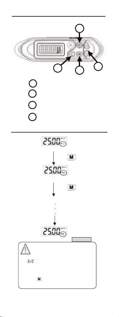
NAMES AND FUNCTIONS OF PARTS
1. Reversible Ratchet
Head
2. Direction Lever
3. LCD Readout
4. Beeper
5. Calibration Port
6. Button
7. Battery Compartment
8. Battery Cover
9. Ratchet Driver
10. Anti-slip Handle
11. LED Indicator
12. Torque Value
13. Memory Number
14. Unit (N-m, ft-lb,
in-lb, kg-cm)
15. Peak/Track Mode
16. Power on/Clear Button
17. Pre-setting Number
Selection
18. Unit Setting/Selection
Button
19. Up/Down Button
12
9
11
34567
8
10
12
1315
14 17
16 18
19

3
2
SELECTION GUIDE
Model
Square
Drive
Max. Operation Range
JDTW-
14250
1/4”
30 N-m / 22 .12 ft-lb
265.5 in-lb / 306.1 kg-cm
JDTW-
38100
3/8”
135 N-m / 99 .5 ft-lb
1195 in-lb / 13 7 8 kg-cm
JDTW-
12150
1/2”
200 N-m / 147.5 ft -lb
1770 in-lb / 204 1 kg-cm
JDTW-
12250
1/2”
340 N-m / 250.7 ft -lb
3009 in-lb / 346 9 kg-cm
SPECIFICATIONS
Model
No.
Square
Drive
Max.
Operation
Range
(ft/lbs )
Alarm
Setting
Range
(ft/lbs )
Length
(mm )
JDTW-
14250
1/4”
22.12
1.11~22.12
390
JDTW-
38100
3/8”
99.5
5~99.5
415
JDTW-
12150
1/2”
147.7
7.4~147.7
530
JDTW-
12250
1/2”
250.5
12.5~250.5
650
All Models
Accuracy*1
CW±2%
CCW: ±3%
Mem ory
50 records
Pre-Set values
9
Communication
Models designated “-C” only.
Check model number on
package or case sticker
Operation Mode
Peak Hold/Track
Unit Selection
N-m, in-lb, ft-lb, kg-cm
Hea d Ty pe
Lever Type Ratchet
Gear Teeth
36
Button
5
Battery
AA x 2
Battery Life *2
(Continuous
oper atio n)
110 hrs.
Battery Life *2
(Standby)
12 months

4
3
SPECIFICATIONS
Operating
Temperature
-10~ 60
Stora ge
Temperature
-20~ 70
Humidity
Up to 90% non-condensing
Drop Te st
1 m
Vibr ation Test *3
10G
Life time *4
10,000 cycle
Envir onm e ntal
test *5
Pass
Electromagnetic
compatibility test
*6
Pass
Note:
*1. Accuracy of readout is guaranteed from 20% to
100% of maximum range + /-1 increment. The
torque accuracy is a typical value. Calibration
point is at the middle line of black circle area on
the rubber grip. To maintain accuracy, calibrate
the wrench at least once per year
*2. Use two AA batteries (Test condition: Toshiba
carbon-zinc battery)
*3. Horizontal and vertical test
*4. One cycle means swing the torque wrench from 0
ft/lbs to maximum range and back to 0
*5. Environmental test:
a. Dry heat
b. Cold
c. Damp heat
d. Change of temperature
e. Impact (shock)
f. Vibration
g. Drop
*6. Electromagnetic compatibility test:
a. Electrostatic discharge immunity (ESD)
b. Radiated susceptibility
c. Radiated emission

5
4
BEFORE USING THE WRENCH
BATTERY INSTALLATION
POWER ON AND RESETTING THE WRENCH
Press to power on digital torque wrench.
Press to reset digital torque wrench
before using it.
ATTENTION:
If an external force is applied to the torque wrench
during power-on/reset or wake up period, an initial
torque offset will be recorded in the memory. Ensure
no load is applied during start up.

6
5
ACTIVATION DURING SLEEP MODE
The wrench will auto sleep after about 5
minutes idle t i m e to save power.
Press to activate wrench during sleep
mode.
RESETTING THE WRENCH
If wrench does not function normally,
press together to reset wrench.
LOW BATTERY VOLTAGE PROTECTION
If battery voltage is under 2.3 volts, wrench
will display a battery symbol and then turn
off after a while.
WHEN USING THE WR
h does not function normally,

7
6
SETUP
STEP 1: PRE-SETTING NO.
2
1
3
Unit Selection/Setting
3
Adjust Torque Value
2
1
Power On/Clear
4
Pre-Setting No.
4
Note:
1. If appe ars, torq ue has been ap plied in
exces s of 110% of maximum v alue. R ecalibra tion is
req uir e d .
2. Th e m aximum number of preset v a l ues is 9.
3. Th e Pr eset Memory n umber is seque ntia l . C ontinue
pres s ing
The Preset Mem ory n u mber is seque n t ial. Contin ue
to scroll thr ough all 9 choic es.
4. If a memory v a lue is adj uste d, the new value wi ll be
stor e d a u t o matically .
*Note1, 2, 3
Pre-set ting N o.: M1
Press
Press
Pre-set ting N o.: M3
Pre-set ting N o.: M2
Pre-set ting N o.: M9
STEP 1: PRE-SETTING NO.

8
7
STEP 2: UNIT SELECTION
STEP 3: SET MAXIMUM TORQUE VALUE
Note:
1. Th e “Unit Select ion” is s e qu e nt i al . C o nt i nu e p r es s in g
to scrol l t hrough all 4 choices .
Pre-setting Torque Value
Decrease Max. Torque
Valu e
Press
Press
Increase Max. Torque Value
Pre-s etting Un it: N-m
Press
Unit Selection: kg-cm
Unit Selection: in-lb
Unit Selection: ft-lb
Press
Press

9
8
STEP 4: PEAK HOLD/TRACK MODE
SELECTION
Peak Mode
Set Peak/Track mode
Set Peak/Track mode
Track Mode
Press and hold
Press for Selection
Press
Press for Selection
Press for Selection
Note:
1. The “Peak/Track” mode is sequential. Press
The “Peak/Track” mode is sequential. Press
or
The “Peak/Track” mode is sequential. Press
to scrol l bet ween choices

10
9
TRACK MODE OPERATION
Long Beep
(((((((( )))))))) ((((((( )))))))
Note:
1. If appe ars, torqu e has been ap plied in excess
of 11 0% of maximu m value. R ecalibra t i on is re q u ired.
2. Wh en using Tr ack mode LC D w il l begin to show
chan g es af t er 5 Nm has been a pplied. If applied torq u e
is less than 5 Nm display will show no change.
3. The green LED’s will light at 80%, 85%, 90%, 95%, and
97. 5 % of set tor que valu e to show progres s .
4. The red LED’s will light at 100% of set torque value.
Bee per t one will be steady until han dle is releas ed. T his
is a stop signal.
5. Unit dis plays 0 w hen handle is released .
Apply Torque Over 5 N-m
Current Torque Value
*Note 1
START
(System initial)
((…((……))…)) ((…(( ……)) …))
Short
Beeps
Red LED
Max. Set Torque or greater
Max. Target Value
Green LED
Over 80% of Set Torque
Over Max. Target Value
Over 80% of Max. Target Value
*Note 4
*Note 2
*Note 3

11
10
PEAK HOLD MODE OPERATION
Red LED
Max. Set Torque or greater
Long Beep
(((((((( ))))) ))) ((((((( )))))))
Over Max. Target Value
Current Max. Value
(Peak Hold)
START
Apply Torque
Note:
1. If appears, torque h as be en appli ed i n excess of 11 0%
of max i mum value . R ecal i bration is requir ed.
2. Press while dis play is flasing to r ec o r d v alue. If
appe ars wrench me m ory is full a nd the next value cannot be
writ t en in. Pl eas e ref er to “ Peak Hol d Mode Rec orded Value
Review” s ection to clear memory data . S k i p t his step if record ing
of dat a is not requi r ed.
3. The green LED’s will light at 80%, 85%, 90%, 95%, and 97.5%
of set torque value to show p r ogress.
4. The red LED’s will light at 100% of set torque value. Beeper tone
will be steady until h andl e is rel eased . T his is a st op signal.
5. Unit display s peak torque a pplied un t il reset or us ed again.
((…((……))…)) ((…(( ……)) …))
Short
Beeps
Green LED
Over 80% of Set Torque
Flashing
Apply Torque Over 5 N-m
Released
Max. Target Value
Over 80% of Max. Target Value
Recording
*Note 2
*Note 1
(System initial)
*Note 3
*Note 4

12
11
PEAK HOLD MODE RECORDED
VALUE REVIEW
Note:
1. Th e “Pea k Hold” mode rec orded value review can also be
used in “Track” mode operati on.
2. If o p erated in the “Peak Hold” mod e, th e dis p lay w ill
show P lease go to next step.
3. If t he rec or d is emp t y , d isplay will sh ow . Use an d
If the rec or d is emp t y , d isplay will show
to r eview recor ds. D isplay will alter n ate betwee n Rec ord
no. a nd recor ded value. P ress to clear or to store
valu e and retur n to r eady mode.
4. Com m unicatio n i s not supporte d on all models .
5. C ommunicat i o n mo d e is also for cali brat i on of t or q ue w rench.
Ple ase co ntact your loc a l d ealer or JET Equ ip men t & Tools
for mo re infor m ation.
Pres s
Peak Hold/Track Mode
Set Peak/Track Mode
Auto Change
Record No.
*Note 2
Record Value
Long Press
Pres s
Communication
*Note 3
*Note 1
Clear Record
Press
Peak Hold /Track Mode
No
(Giv e u p)
*Note 4, 5, 6
(Exit)
Commu n ication
Delet ed
(Clear )
Yes
Press

13
12
COMMUNICATION
CONNECTING COMMUNICATION CABLE
Turn off power and then connect the accessory
cable between the RS232 COM port of PC and
torque wrench.
UPLOADING RECORD DATA
Make sure the connection between PC and
wrench is working.
Presstogether to reset the wrench.
Change the wrench operation mode to “Send”.
(Please refer to “P eak Hol d Mo de Re cor de d
Value Review” section)
Use PC to start the uploader program.
In uploader program, first select the correct
COM port No.
Next, select the file path to save the uploaded
data.
Finally, press “upload” button to transmit the
torque records to PC.
The uploaded data is saved as a *.csv file. Use
Microsoft Excel to view *.csv file.
Preca uti o n:
1. Communication function is only supported
on some models. Check the model no. and
its specification before using communication
function.
2. Do not insert the plug of communication
cable into torque wrench that does not
support communication function.
CAUTIONS:
Refer to the uploader program user guide
for detailed instructions.

14
13
MAINTENANCE AND STORAGE
CAUTION:
1. Over-tor que (105% of
Max. torque range)
could cause breakage
or loss of accuracy.
2. Do not shake violently
or drop wrench.
3. Do not use this wrench
as a hammer.
4. Do not leave this wrench in any place exposed
to excessive heat, humidity, or direct sunlight.
5. Do not use this wrench in water.
6. If the wrench gets wet, wipe it with a dry towel
as soon as possible. The salt in seawater can
be especially damaging.
7. Do not use organic solvents, such as alcohol or
paint thinner when cleaning the wrench.
8. Keep this wrench away from magnets.
9. Do not expose this wrench to dust or sand as
this could cause serious damage.
10. Do not apply excessive force to the LCD panel.
BATTERY MAINTENANCE
1. When the wrench is not used for an extended
period of time, remove the battery.
2. Keep a spare battery on hand when going on a
long trip or to cold areas.
3. Do not mix battery types or combine used
batteries with new ones.
4. Sweat, oil and water can prevent a battery’s
terminal from making electrical contact. To
avoid this, wipe both terminals before loading
a battery.
5. Dispose of batteries in a designated disposal
area. Do not throw batteries into a fire.
WARRANTY
JET Digital torque wrenches are warranteed to be
free of factory defects. Calibration is the
responsibility of the user and is not covered. For
warranty details, consult the JET hand tools
catalogue or your local distributor.
AT TENTI ON:
One-year periodic recalibration is necessary
to maintain accuracy.
Please contact your local dealer for
calibrations.
This manual suits for next models
4
Table of contents
Other Jet Power Tools manuals