Jet HBS-1018W User manual

- - - - - - - - -- -- --- - -------
..JET
EQUIPMENT & TOOLS
OPERATOR'S MANUAL
HBS-916W & 1018W Bandsaws
j-- ..
p
JET EQUIPMENT &.TOOLS, INC.
A WMH Company
www.jettools.com
P.O. BOX 1349
Auburn, WA 98071-1349
253-351-6000
Fax 253-939-8001
M-414468 2/99

Important Information
1-YEAR
LIMITED WARRANTY JET offers a one-year limited
warranty on this product
REPLACEMENT PARTS
Replacement parts for this tool are availabledirectlyform JET Equipment& Tools.
To place an order, call 1-800-274-6848. Pleasehave thefollowing informationready:
1. Visa, MasterCard, or DiscoverCard number
2. Expirationdate
3. Part number listedwithin this manual
4. Shipping address other than a PostOffice box.
REPLACEMENT PART WARRANTY
JET Equipment & Tools makes every effort to assurethat parts meet high quality and durability standards
and warrants to the original retail consumer/purchaserof our parts that each such part(s) to be free from
defects in materials and workmanshipfor a period of thirty (30) days from the date of purchase.
PROOF OF PURCHASE
Please retainyour dated sales receiptas proofof purchaseto validate thewarranty period.
LIMITED TOOL AND EQUIPMENTWARRANTY
JET makes every effort to assure that its products meet high quality and durability standards and warrants to the
original retail consumer/purchaser of our products that each product be free from defects in materials and
workmanship as follows: 1 YEAR LIMITED WARRANTY ON THIS JET PRODUCT. Warranty does not apply to
defects due directly or indirectly to misuse, abuse, negligence or accidents, repairs or alterations outside our
facilities or to a lack of maintenance. JET LIMITS ALL IMPLIED WARRANTIES TO THE PERIOD SPECIFIED
ABOVE FROM THE DATE THE PRODUCTWAS PURCHASEDAT RETAIL. EXCEPT AS STATED HEREIN, ANY
IMPLIED WARRANTIES OR MECHANTABILITY AND FITNESS ARE EXCLUDED. SOME STATES DO NOT
ALLOW LIMITATIONS ON HOW LONG THE IMPLIED WARRANTY LASTS, SO THE ABOVE LIMITATION MAY
NOT APPLY TO YOU. JET SHALL IN NO EVENT BE LIABLE FOR DEATH, INJURIES TO PERSONS OR
PROPERY OR FOR INCIDENTAL, CONTINGENT, SPECIAL OR CONSEQUENTIAL DAMAGES ARISING FROM
THE USE OF OUR PRODUCTS. SOME STATESDONOTALLOWTHI; I;XCiLU~IONORLIMITATIONOF
INCIDENTAlORCONS~OUENTIAlDAMAG~S,~o T~~ AQOV~LIMITATIO~ O~ ~~~LUQIO~UA V ~CT A~~L V
TO YOU. To take advantage of this warranty, the product or part must be returned for examination, postage
prepaid, to an authorized service station designated by our Auburn office. Proof of purchase date and an
explanation of the complaint must accompany the merchandise. If our inspection discloses a defect, JET will either
repair or replace the product or refund the purchase price, if we cannot readily and quickly provide a repair or
replacement, if you are willing to accept such refund. JET will return repaired product or replacement at JET's
expense, but if it is determined there is no defect, or that the defect resulted from causes not within the scope of
JET's warranty, then the user must bear the cost of storing and returning the product. This warranty gives you
specific legal rights, and you have other rights, which vary, from state to state.
JET Equipment & Tools. P.O. Box 1349, Auburn, WA 98071-1349 .(253) 351-6000

it WARNING
.Read and understand the entire
instruction manual before attempting
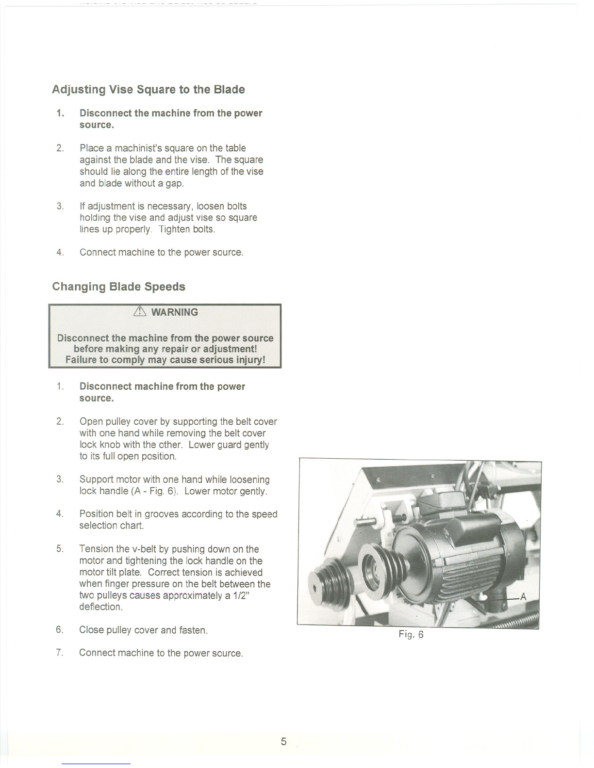
assembly or operation.
All JET bandsaws are designed and
intended for use by properly trained and
experienced personnel only. If you are
not familiar with the proper and safe
operation of a bandsaw, do not use until
proper training and knowledge have
been obtained.
.
.Always wear approved safety glasses/face
shields while usingthis machine.
.Make certain the machine is properly
grounded.
.Before operating the machine, remove tie,
rings,watches, otherjewelry, and roll up
sleeves above the elbows. Removeall
loose clothing and confine long hair. Do
NOT wear gloves.
.Keepthe floor around the machineclean
and free of scrap material, oil and grease.
.Keep machine guards in place at all times
when the machine is in use. If removedfor
maintenance purposes, use extremecaution
and replace the guards immediately.
.Do NOT over reach. Maintain a balanced
stance at alltimes so that you do not fall or
lean against bladesor other moving parts.
.Make all machine adjustmentsor
maintenancewith the machine unplugged
from the power source.
.Use the right tool. Don'tforce a tool or
attachment to do a job which it was not
designed for.
.Replace warning labels if they become
obscured or removed.
.Make certain the motorswitch is in the OFF
position before connecting the machineto
the powersupply.
.Giveyour work undividedattention. Looking
around, carrying on a conversation, and
"horse-play"are careless acts that can
result in serious injury.
.Keepvisitors a safe distance from the work
area.
.Use recommendedaccessories; improper
accessories may be hazardous.
.Make a habit of checking to see that keys
and adjusting wrenches are removed before
turning on the machine.
.Always keep hands and fingers away from
the bladewhen the machine is running.
.Never hand holdthe material. Always use
the vise andclamp it securely.
.Keep belt guard, blade guards, and wheel
covers in place and inworking order.
.Always provideadequate support for long
and heavy material.
.Use a sharp blade and keep machine clean
for best and safest performance.
.Failureto complywith all of these warnings
may cause serious injury.

Specifications: HBS-916W HBS-1018W
StockNumber ""'" 414468 ..414473
Capacity:
Round at 900 9" 10"
Round at 450 7-3/4" 8-1/2"
Rectangle at 900 2"x16" - 9"x14" '2" x 18"- 10" x 15"
Rectangle at 450 9"x7-3/4" """""""""""""'"'''''''''''''''''''''''' 10"x 8-112"
Blade Size 1"xO.032"x119-1I2" 1.0"x 0.032" x 130"
Blade Wheel Diameter 13" 13"
Blade Wheel Speed 82,132,170,235 SFPM 82,132,210,330 SFPM
Motor(TEFC) 1-1I2 HP ,1 Ph 115/230V 2HP, 1Ph,230V
Prewired 115V """"""""'''''''''''''''''''''''''''''' .230V only
Lowered Height ..0...41 " ".. """""'''' ..'"'' "'"'''' 43"
Raised Height 65"... " '''''' ""'''''' 69"
Bed Height 0" """"""""""""" 25" 0 0 0.00"""""""',," 0.0 25"
Overall Dimensions (approx.) "'"'' 65"L x 28"W """""""""""""""'"'''''''''''''' 70"L x 31"W
Net Weight (approx.) """"'''''''''''''''''''''''' 625 Ibs. " 776 Ibs.
Shipping Weight (approx.) 704lbs. 864Ibs.
Table of Contents
Uncrating and Cleanup 0 0""""""',"'...0 0...1
Installation .1
Assembly 1-2
ElectricalConnections 0...0 0 0..3
Controls 0 0 00 0 0 0"""""""""""""""" 0 0 3
Prior To Operation 4
Adjusting Vise Square to Blade "'"'''''''''''''''''''''''''''''''''''''''''''''''''''''''''''''' ''''''' 5
Changing Blade Speeds 05
Adjusting Feed Rate 06
Changing Blades 6
Blade Tracking Adjustment """""""'"'''' 0.7
Automatic Shut-Off Adjustment 0.0 0 0 8
Thrust Roller Adjustment 08
Guide Roller Adjustment
0
0
9
BowWeight Adjustment 0...0 0 0 0 9
ViseAdjustment 0 00...0 0 0 0 ..0..0 ..0 ..0 0 10
Maintenance 0..0...0 0 0...10
Lubrication 0 00..0.00 0 00..0 0.0...0 0"...0..0,,0 10-11
Parts Breakdown ... ..0 """"""""" 12-14
Parts List 0..0 0 """"""","""""""'" ,... "0.. 15-23
Electrical Schematic..o.. 0..0.0.0 ' 0 00"""..0...0.0.0..0 ""0 000""""""""""""0 24-25
The specifications in this manualare given as general informationand are not binding. JET Equipment
and Tools reserves the right to effect, at any time andwithout prior notice, changes or alterations to parts,
fittings, and accessoryequipment deemed necessaryfor any reasonwhatsoever.

Uncrating and Cleanup
Note: Readand understandthe entire manualbefore
attempting setup or operation.
1. Finish uncrating the saw and inspectfor
damage. Should any have occurred,contact
your local distributor.
2. Remove all bolts attaching machineto
shipping base.
3. Leave packing material betweenvice clamps
and saw head intact until bandsawhas been
lifted to its final position.
4. Clean all rust protectedsurfaces with
kerosene or diesel oil to remove protective
coating. Do not use gasoline, paintthinner,
mineral spirits, etc. These may damage
painted surfaces.
5. Lubricate all slideways with SAE 1OWoil.
Installation
For best performance,the bandsawshould be
located on a solid and levelfoundation. Allow room
for servicing and for moving large stock aroundthe
bandsaw when deciding a locationfor the machine.
1. Using lifting straps that are isolatedfrom the
bandsaw's finished surfaces, lift machineplace
in desired location. See figure 1 for strap
placement.
2. Install four leveling bolts with lock nuts on both
sides of the base as shown in the parts
breakdown on page 12- items#2 and#3.
3. Place a level on the table surface and check
side to side and front to back.
4. Adjust leveling screws until machine is level in
both directions and tighten locking nuts.
Assembly
1. Unbolt the motor assembly fromthe shipping
crate bottom.
2. Remove nut and washer from the motor
support shaft.
Fig. 1
1

3. Remove shaft (A- Fig. 2) from the motor mount
bracket.
4. Carefully lift motor and line up holes in the
motor mounting plate and the motor bracket.
5. Slide motor support shaft into motor mount
bracket to hold the motor in place.
6. Fasten shaft with nut and washer.
7. Loosen strain relief nut on the motorjunction
box. Removethe junction box cover. Insert
wire through strain reliefand wire to the
terminal strip usingthe diagramon thejunction
box cover. Tighten the strain relief nut and
replace the junction box cover.
Remove two hex cap bolts and washers
8. (A, Fig. 3) from the right side of the saw arm.
9. Slide belt cover (8, Fig. 3) around pulley shafts
and attach to saw with two hex cap boltsand
two washers.
10. Lift motor and place v-belt around both pulleys.
Lower motor.
11. Tension the v-belt by pushingdown on the
motor and tightening the lock handleon the
motor tilt plate. Correct tension is achieved
when finger pressure between the two pulleys
causes approximatelya 1/2"deflection. See
Figure4.
12. Close pulley cover door and fastenwith lock
knob.
13. Fasten work stop rod (#17 - page 12) to saw
bed (#11) by inserting into bedand turning
clockwise untiltight. Placework stop bracket
(#16) onto stop rod (#17) and tighten lock
handle (#20). Attach stop screw (#19)to stop
bracket (#16) with lock handle (#18) and
tighten.
Fig. 2
Fig. 3
Fig. 4
2

Electrical Connections
it WARNING
All electrical connections must be done by a
qualified electrician! Failure to comply may
result in serious injury!
it WARNING
Disconnect machine from the power source
before changing any voltage components!
Failure to comply may cause serious injury!
The HBS-916W bandsaw is ratedat 115/230V,1Ph.
and is prewired 115 volt from the factory. The
HBS1018Wis rated at 230V, 1Ph.only. Confirm
power available at the saw's location is the sameas
the saw is wired. To switch the HBS-916Wfrom
115Vto 230V, the following itemswill haveto be
changed:
.Main Motor - follow diagram insidejunction box
cover.
.Coolant Pump - Removechip panon front of
saw, removejunction box cover on pump, and
follow diagram insidejunction box cover.
.Control Transformer - Open electrical panel
on rear of base and switch primarywire on
transformer from 115Vto 230V.
Machine must always be correctly grounded.
Note:The powercord end will haveto bechanged
to one that is rated 230V when changingto the
highervoltage.
Controls - Figure 5
A. Power Indicator Light (A) - litwhenever
machine is running.
B. Start Button (B) - depress to start bandsaw.
C. Emergency Stop Button (C) - depress to
immediately stop all machine functions.
o. Coolant Switch (0) - Turn arrowto "I" to turn
on flow of coolant. Turn arrow to "0" to stop
flow of coolant. Fig. 5
3

E. Cutting PressureControl (E)- turn clockwise
to decrease cutting pressure. Turn counter-
clockwise to increase cutting pressure.
F. Hydraulic On-Off Valve (F) - turns hydraulic
cylinder on and off.
Prior to Operation
1. Check bladetooth direction matchesdiagram
on blade guides.
2. Check to see that blade is properly seated on
wheels after applying correct tension
(approximately25,000 Ibs.).
3. Set blade holder guides for approximately
.003"to .005" clearance betweenthe guides
and blade.
4. Check for slight clearance between back up
rollers and back of blade.
5. Position blade guides as close to work piece
as possible.
6. Select proper speed and feed rate for material
being cut. See speed selection chart found in
the enclosed "Guide to Bandsawing"booklet
supplied with this saw.
7. Material to be cut must be securely held in
vise.
8. Check to see that coolant level is adequate
and turn on coolant pump if materialto be cut
requires it. Machine should be filled with four
gallons of the propercoolant mixture. Follow
the directions on the product makers label and
fill the coolant tank throughthe chip tray area.
9. Do not start cut on a sharp edge.
10. Keepmachinelubricated. See "Lubrication"
section.
4

Adjusting Vise Square to the Blade
1. Disconnect the machine from the power
source.
2. Place a machinist's square on the table
against the blade and the vise. The square
should lie along the entire lengthof thevise
and blade without a gap.
3. If adjustment is necessary, loosen bolts
holding the vise and adjust vise so square
lines up properly. Tighten bolts.
4. Connect machineto the powersource.
Changing Blade Speeds
it. WARNING
Disconnect the machine from the power source
before making any repair or adjustment!
Failure to comply may cause serious injury!
1. Disconnect machine from the power
source.
2. Open pulley cover by supportingthe belt cover
with one handwhile removingthe beltcover
lock knob with the other. Lowerguard gently
to its full open position.
3. Support motorwith one handwhile loosening
lock handle (A - Fig.6). Lowermotorgently.
4. Position belt in grooves accordingto the speed
selection chart.
5. Tension the v-belt by pushingdown on the
motor and tightening the lock handleon the
motor tilt plate. Correct tension is achieved
when finger pressure on the belt betweenthe
two pulleys causes approximately a 1/2"
deflection.
6. Close pulley cover and fasten. Fig. 6
7. Connect machineto the powersource.
5

Adjusting Feed Rate
Rateof feed is adjusted by turningthe cutting
pressure control knob on the control panel. Rateof
feed is important to bandsawperformance;
excessive pressure may breakthe bladeor stall the
saw. Insufficient pressure rapidly dulls the blade.
Materialchips or shavings are the best indicatorof
proper speed and pressure. The idealchip isthin,
tightly curled, and warm to the touch. Chipsthat
range from golden brown to black indicate
excessive force. Bluechips indicateextreme heat
from too high a band speed which will shorten blade
life. Thin or powderedchips indicateinsufficient
feed pressure.
A detailed explanation on feed rate can be found in
the enclosed "Guide to Band Sawing"published by
American Saw and ManufacturingCompany.
Reprinted by permission.
Changing Blades
it. WARNING
Disconnect machine from the power source
before making any adjustments or repairs!
Failure tQ comply l1'1ayresult in serious injury!
1. Disconnect machine from power source.
2. Raise saw arm approximately6". Hold saw
arm in place by closing cutting pressure
control valve. Remove screw (#145),
washer(#146), and brush (#147)from the wire
brush post (#148) as shown on page 13.
3. Open bothwheel covers andclean chips out
of bothwheel housings. Loosentwo lock
knobs and remove upper bladeguard.
4. Release bladetension by turning blade
tensioning handwheel (A - Fig.7)counter-
clockwise until blade is free.
5. Loosen lock knoband slide left bladeguide
arm (B) to the right as far as possible.
6. Remove old blade from bothwheels and out of
each bladeguide. it Caution:Evendull
6
B
Fig. 7

blades are sharp to the skin! Useextra
caution handling bandsawblades!
7. Install new blade makingsure teeth are
pointed downward in the proper cutting
direction. If necessary,turn bladeinsideout.
8. Position bladeon bandwheels and tightenjust
enough to hold blade on wheels. Make sure
back of blade rests lightlyagainst thewheel
flange of both wheels. Twist blade slightlyto
allow it to slip into guides.
9. Tension bladeto approximately25,000Ibs.of
blade tension, as indicatedon the blade
tension indicator found on the tensionwheel
shaft housing.
10. Attach wire brush to thewire brush postwith
screw andwasher. Adjust wire brush postso
that brushjust comes into contact with blade
teeth.
11. Close all covers and guards andfasten
securely. Connect machineto power and run
freely for approximately two minutes.
12. Turn power off and re-check bladetensionand
wire brush adjustment. If further adjustment is
necessary, disconnect saw from power
source, make adjustments,and re-connectto
power.
Blade Tracking Adjustment
Blade tracking has been set at the factory and
should require no adjustment. If a tracking problem
occurs, adjust the machine as follows:
~WARNING
Tracking adjustment is done with the wheel
covers open to observe the blade. Use extreme
caution so as not to come into contact withthe
blade!
Since tracking can only be adjusted while machine
is running, it is suggested that this adjustmentbe
accomplished by qualified personnelthat are
familiar with this type of adjustmentand the dangers
associated with it.
'7

1. Disconnect machine from the power
source.
2. Raise saw arm to its highest position and
close cutting pressurecontrol valve to hold
saw arm in place.
3. Locate tracking adjustment plate on the back
side of the driven blade wheel.
4. Loosen the three bolts (A - Fig. 8) locatedon
the top of the tracking nuts.
5. Tracking adjustment is accomplishedby either
looseningor tighteningthree adjusting nuts
(B - Fig. 8).
6. Tracking is set properlywhen the back of the
blade lightly touchesthe wheel flange. Note:
over-tracking (allowing blade back to rub hard
against wheel flange)will damage the blade
wheels and blade.
7. Tighten locking bolts (A)once properly
tracking is completed.
8. Connect machineto the power source.
Automatic Shut-Off Adjustment
The motor should shut off immediatelyafter the
blade has cut through the materialandjust before
the head comes to rest on the horizontalstop bolt.
If the machine continues to run after the work piece
has been fully cut, locateand adjust the micro
switch mounting plate down. If the machineshuts
off before the work piece has been completelycut,
move the micro switch mounting plate up.
Thrust Roller Adjustment
1. Disconnect machine from the power
source.
2. Loosen two hex socket cap screws (A - Fig.
9). Note: Left guide roller has two hex socket
cap screw; right guide roller has one (HBS-
916Wonly) The HBS-1018Whas two
screws on each guide..
3. Move guide seat (B) up or down untila
clearance of .003"to .005"between backof
blade and thrust roller is obtained.
Fig. 9
8

4. Tighten two hex socket cap screws (A).
5. Repeat for other bladeguideassembly.
6. Connect machineto power source.
Guide Roller Adjustment
1. Disconnect machine from the power
source.
2. Loosen blade guides (A- Fig. 10)by loosening
screws (B). Slide blade guides awayfrom
blade.
guideseat
B
3. Loosen lockingscrews (C) by usinga hex
wrench.
4. Adjust the eccentric bushingswith a
combination wrench until the ball bearingsare
snug to the blade. Note: bladeshouldtravel
freely up and down betweenthe ball bearings.
Do not pinch the blade. A
5. Fig. 10
Tighten locking screws (C).
6. Slide blade guides back into contact with blade
and tighten screws (B).
7. Connect machineto the power source.
Bow Weight Adjustment
Bowweight is one of the most important
adjustments ofthe saw. If the bowweight is not set
properly, one can expect poor performance,
crooked cuts, tooth stripping, stalling, and the blade
popping off the bladewheels. The hydraulicfeed
rate unit will not compensate for improper bow
weight. Bowweight has beenset at the factory and
should not need any adjustment. If adjustmentis
necessary:
1. Disconnect the machine from the power
source.
2. Turn hydraulic valve to on (F - Fig. 5)
3. Turn cutting pressure control valve (E - Fig. 5)
counter-clockwise until it stops.
9

1. Place one end of a fish-type scale under the
blade tension handle and lift the sawwith the
other end. The scale should indicate
approximately 18-20 Ibs.for the HBS-916W.
For the HBS-1018W, it should indicate22-24
Ibs.
2. Adjust tension to approximately 18-20 Ibs.(or
22-24 Ibs.) by turning the adjustable C-bolt
found at the end of the coil spring on the rear
of the bandsaw.
3. Connect the machine to the powersource.
Vise Adjustment
To position the moveablevise jaw:
1. Turn vise handwheel (A - Fig. 11) 1/2turn
counter-clockwise.
2. Move rack block (B - Fig. 11)to desired
location by sliding along the bed. Placethe
rack block onto the rack.
3. Turn the handwheel to tighten the vise.
To adjust the vise for angle cutting:
1. Loosen bolts and movevise jaw (C-Fig11) to
desired location.
2. Set the vise to desired angle, reinstall nuts and
Tighten the nut and bolt assemblies.
3. Adjust the movable vise parallel to the fixed
vise by loosening bolt (D-Fig.11) adjustingto
parallel and tightening bolt.
Maintenance
Keep the band saw and the motor clean.
Lubrication
All ball bearings are permanently lubricated and
sealed. They require nofurther lubrication.
The gear box lubricant should be changed after the
first 50 hours of operation. Change lubricantfrom
then on every 250 hours of operation.
c
10

To check level of gear box lubricant, place sawarm
in down position and allow a few minutesto pass
so that oil drains down. Check level in sight glass
on side of gear casing. Correct level is the dot in
the middle of sight glass.
To change gear box lubricant:
1. Disconnect machine from the power source.
2. Open drain plug and allow lubricant to drain
completely. Drain plug may be found on lower
front of gear case under right wheel cover.
Remove drain plug with a hex wrench.
3. Replace drain plug.
4. Remove filler cap (A - Fig. 12) and fill gear box
with Mobil DTE@ Oil Heavy Medium until level
reaches dot in middle of sight glass.
5. Replace filler cap.
6. Connect machine to the power source.
Use a light machine oil to lubricate all other moving
parts as needed
A detailed explanation on blade selection and
blade problems and their solutions can be found in
the enclosed "Guide to Band Sawing" published by
American Sawand Manufacturing Company. Used
by permission.
11
Fig. 12

~
:c
E
Q)
en
en
<
"C
Q)
[Q
"C
C
ns
Q)
I/)
ns
[Q
/'
<t"
/
73
69-( ---~ Ii 0
I
2~
12161-
~
N
......
~.
203
-1 201
,_./'-~ 202
W)JiJJ~

175111J:IJ
T/6 ,.,
~
8~
~
.c
E
CD
1/1
1/1
<
E
'-
<
~
nI
tn
122
111 121(3)
&
~i"" 9O(" )
111
('f)
~

171,
&~
172 _/~
112(41 113141
111 ',~12~
114 )
107 .~
<1(;;
1084010914) 110
.
'~
"~
O9-1(4 - 114
0~~' I
""""
'.~ ~
~/
>
122
,""'"
99
117 696-1
-80
HBS 916W

Parts List for the HBS-916W/-1018W Bandsaws
Index Part
No. No. Description Size Qty.
1 HBS916W-01 Base (SIN 8081108and lower) 1
HBS916W-01A Base (SIN 8081109and higher) 1
HBS1018W-01 Base (SIN 808718and lower) 1
HBS1018W-01A Base (SIN 808719and higher) 1
2 TS-1492071 ,... HexCap Bolt M12x70 4
3 TS-1540081 Hex Nut M12 4
4 HBS916W-CP Coolant Pump 1
5 TS-1531051. Pan HeadScrew M6x16 2
6 TS-1551061 LockWasher M6 2
8 HBS916W-08 Hose 1
9 HBS916W-09 CoolantGauge 1
9-1 TS-1491041 HexCap Bolt ,.M1OX30 2
9-2 TS-1540071... ""'''''''''''''''' HexNut M10 2
10 HBS916W-10 ChipTray " 1
HBS1018W-10 ChipTray " 1
11 HBS916W-11 Bed(SIN 8081108and lower) 1
HBS916W-11A Bed(SIN 8081109and higher) 1
HBS1018W-11 Bed(SIN808718andlower) "1
HBS1018W-11A Bed(SIN 808719and higher) 1
12 TS-1490051 HexCap BoiL M8x30 8
13 TS-1550061 Washer. """""'"'''''''''''''''''''''''''''''''''''''''''''''' M8 8
14 TS-1551081 LockWasher M8 8
15 TS-1540061 Hex Nut M8 8
16 HBS916W-16 Stop Bracket 1
17 HBS916W-17 Stop Rod 1
18 HBS916W-18 Lock Handle 1
19 HBS916W-19 Work Stop 1
20 HBS916W-20 Lock Knob 1
21 HBS916W-21 HandWheelAssembly 1
HBS1018W-21 HandWheelAssembly 1
22 HBS916W-22 LeadScrewSeat 1
HBS1018W-22 LeadScrewSeat 1
23 TS-1490051 HexCap BoiL M8x30 2
23-1 TS-1551061 LockWasher M8 " 2
23-2 TS-1550061 Washer M8 2
24 HBS916W-24 LeadScrew(SIN 8081108and lower) 1
HBS916W-24A LeadScrew (SIN8081109and higher) 1
HBS1018W-24 LeadScrew (SIN808718and lower) 1
HBS1018W-24A LeadScrew (SIN808719and higher) 1
30 HK-2516-2RS NeedleBearing 2
31 HBS916W-31 Torsion Spring '''''''''''''''''''''''''''''''''' 1
HBS1018W-31 Torsion Spring 1
32 HBS916W-32 PivotShaft 1
32-1 TS-1550041. Washer "'''''''''''''''''''''''''''''''''''''''''''''''''''''''''' M12 2
32-2 HBS916W-32-2 BoltwI Zerk Fitting 2
33 HBS916W-33 Pivot Bracket '''''''''''''''''''''''''''''''''' 1
HBS1018W-33 Pivot Bracket 1
15

34 TS-1540081 Nut M12 1
35 TS-1550081 Washer , M12 1
36 TS-1492041 HexCap Bolt M12x40 1
37 HBS916W-37 Torsion SpringShaft 1
38 HBS916W-38 C-Ring S-22 1
39 TS-1490041 HexCap Bolt M8x25 1
39-1 TS-1551081 LockWasher M8 1
39-2 TS-1550061 Washer M8 1
40 HBS916W-40 MotorTilt Plate 1
HBS1018W-40 " MotorTilt Plate 1
41 HBS916W-41 LimitSwitch Plate 1
42 TS-1550061 Washer M8 2
43 TS-1490031 HexCap Bolt M8x20 2
43-1 ,TS-1551081 LockWasher M8 2
44 TS-1482021 Hex CapScrew M6x12 4
44-1 TS-1441041 Washer M6 4
45 HBS916W-45 LimitSwitch 1
47 HBS916W-47.." CylinderPin 1
" HBS1018W-47A Cylinder Pin 1
48 HBS916W-48 C-Ring S-20 1
49 HBS916W-49 C-Ring S-25 2
50 TS-1491041 Hex Cap Bolt M10x30 1
50-1 TS-1540071 HexNut M10 1
51 HBS916W-51 HydraulicCylinderAssembly 1
HBS1018W-51 HydraulicCylinderAssembly 1
52 HBS916W-52 CylinderPin 1
52-1 HBS916W-52-1 , Pin 1
53 HBS916W-53 " HydraulicMountingPlate- Top " 1
HBS1018W-53 HydraulicMountingPlate- Top 1
53-1 TS-1551071 LockWasher M10 2
53-2 TS-1491041 HexCap Bolt M1Ox30 2
54 TS-1492051 HexCap Bolt M12x50 2
55 ". TS-1550081 Washer... " M12 2
56 HBS916W-56 Plate " 1
57 TS-0561051 HexNut 1/2" 2
58 HBS916W-58. Spring Bracket 1
59 HBS916W-59 ,...AdjustableC-Bolt 1
60 HBS916W-60 " Spring 1
HBS1018W-60 , Spring 1
61 HBS916W-61 Angle Scale 1
62 TS-1492041 Hex Cap BoiL M12x40 2
63 TS-1551081 LockWasher M12 1
63-1 TS-1550081 Washer , M12 2
64 HBS916W-64 Vise Jaw -left " 1
65 T8-1492051 HexCapBolt M12x50 ,1
66 TS-1551081 " LockWasher M12 1
66-1 TS-1550081 Washer M12 1
67 ., HBS916W-67.. , Vise Jaw - right 1
68 TS-1492041 Hex Cap Bolt M12x40 1
68-1 TS-1551081 LockWasher M12 1
69 TS-1503011 HexSocket Cap Bolt M6x8 4
69-1 ,HBS916W-69-1 ,Nut M6 1
70 HBS916W-70 , Electrical Panel Cover (SIN 8081108 and lower HBS-916W) 1
HBS916W-70 " Electrical Panel Cover (SIN 808718 and lower HBS-1018W) 1
16
Other manuals for HBS-1018W
1
This manual suits for next models
1
Table of contents
Other Jet Saw manuals