Jetting MJet V0 HD Installation instructions

MJet V0 HD
Product model/type: MJet V0 HD 18 V
MJet V0 HD 18 V USER'S GUIDE AND SAFETY MANUAL

Copyright © 2020 by Jetting AB
All rights reserved. No part of this publication may be
reproduced, distributed, or transmitted in any form or by
any means, including photocopying, recording, or other
electronic or mechanical methods, without the prior written
permission of the publisher. For permission requests,
write to the publisher, addressed “Attention: Permissions
Coordinator” at the address below.
Jetting AB, Murgatan 1, 522 35 Tidaholm, Sweden
jetting.se
info@jetting.se

Important safety notice
Read and understand all procedures and safety instructions before using the MJet V0 HD micro
fibre blower. Observe all safety information on this page and note specific safety requirements
as explained by procedures in this manual. Failure to follow these instructions could result in serious
personal injury or death.
Caution: Noise will exceed 70 db
Manufacturer
Jetting AB
Murgatan 1
522 35 Tidaholm
Sweden
jetting.se
info@jetting.se
+46 502 65 90 10

Table of contents
General information 1 5
Technical information 2 6
Safe operating practices 3 7
Unpacking the box 4 8
Set up the blower 5 9
Display functions 6 10
Crash test 7 10
Blower operations 8 11
Maintenance 9 12
Troubleshooting guide 10 13
EC Declaration of Conformity 11 14
Notes 12 15
Section Page

1. General information
The MJet V0 and V0 HD is unique devices for installing fiber optic directly into a pipe. The MJet V0 HD is
consist of an air block/pipe clamp and a drive wheel that, when combined installs a fiber into an airtight
pipe. The V0 HD has 200 N in pushingforce and speed is 0-110 m/min.
The MJet V0 HD’s built in adjustable clamp force, greatly optimize the pulling stress on the fiber.
The electronic fiber protection system stops the motor within 250 ms. if the wheels are not running
synchronized (like if the fiber hits an obstruction).
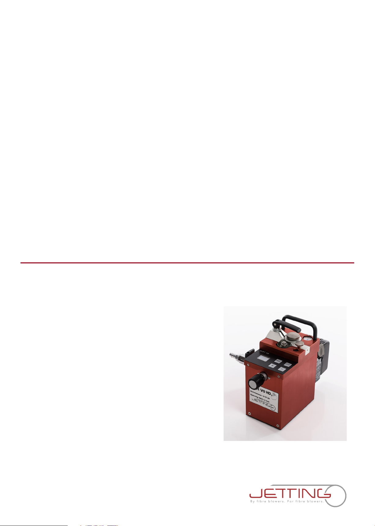
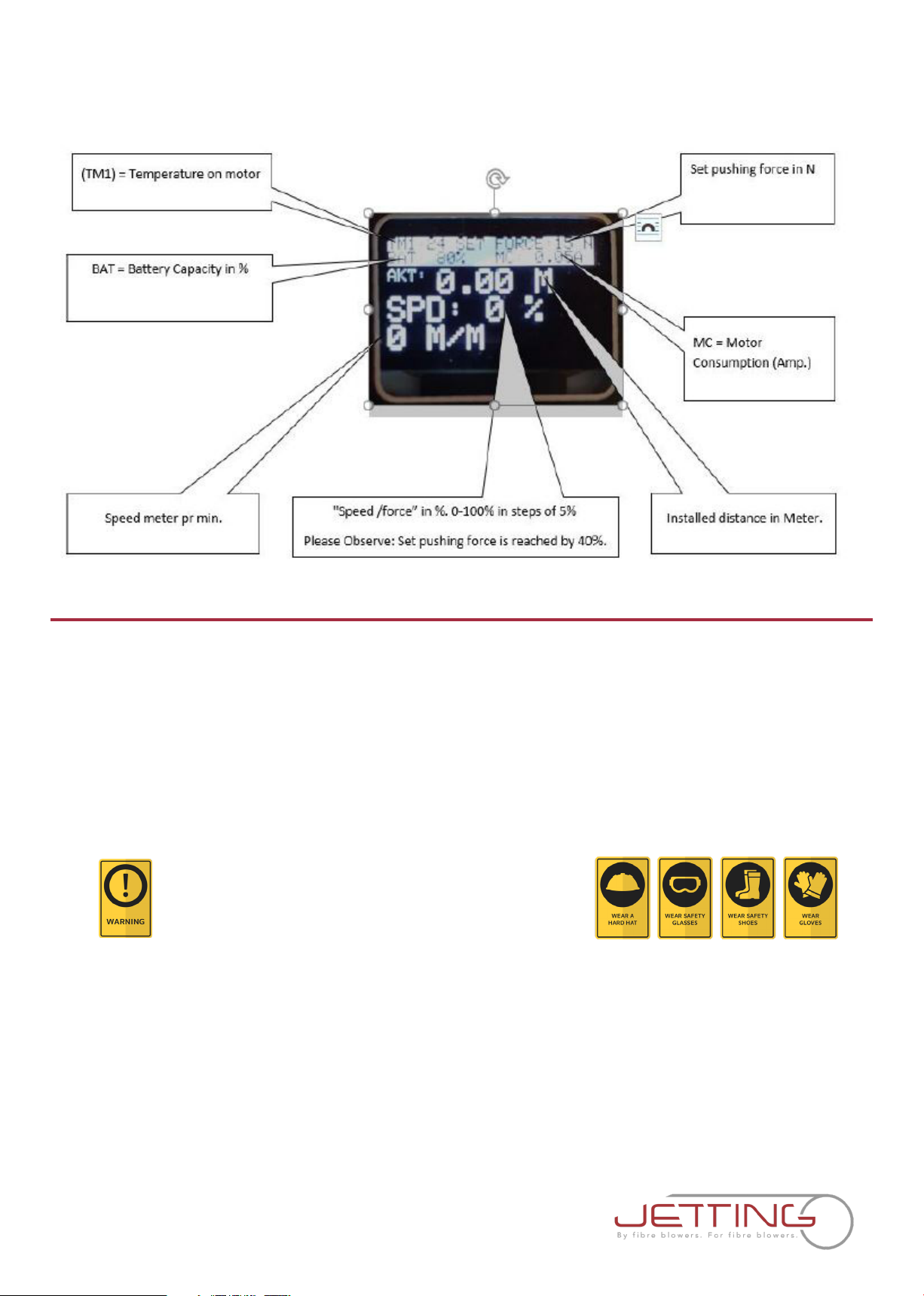
The MJet V0 HD comes standard with a digital LCD Meter Display, 2 pcs 18 V, 4 Ah lithium batteries and
charger in a hard side case.
These operating instructions contain a full description of the MJet V0 HD, which have been designed
for the purpose of feeding fiber through a pipe. The pipe must have previously been installed
underground or overhead to receive the fiber optic and must be of sucient length on exit to be
received by the machine. The pipe must be of material with sucient compression strength for it to be
adequately sealed in the pipe clamps of the machine. The pipe must be airtight up to a pressure of
16bar. Pipe sizes range from 3 mm-16 mm, while fiber optic fiber(s) range from 0,5 mm-6,5 mm.
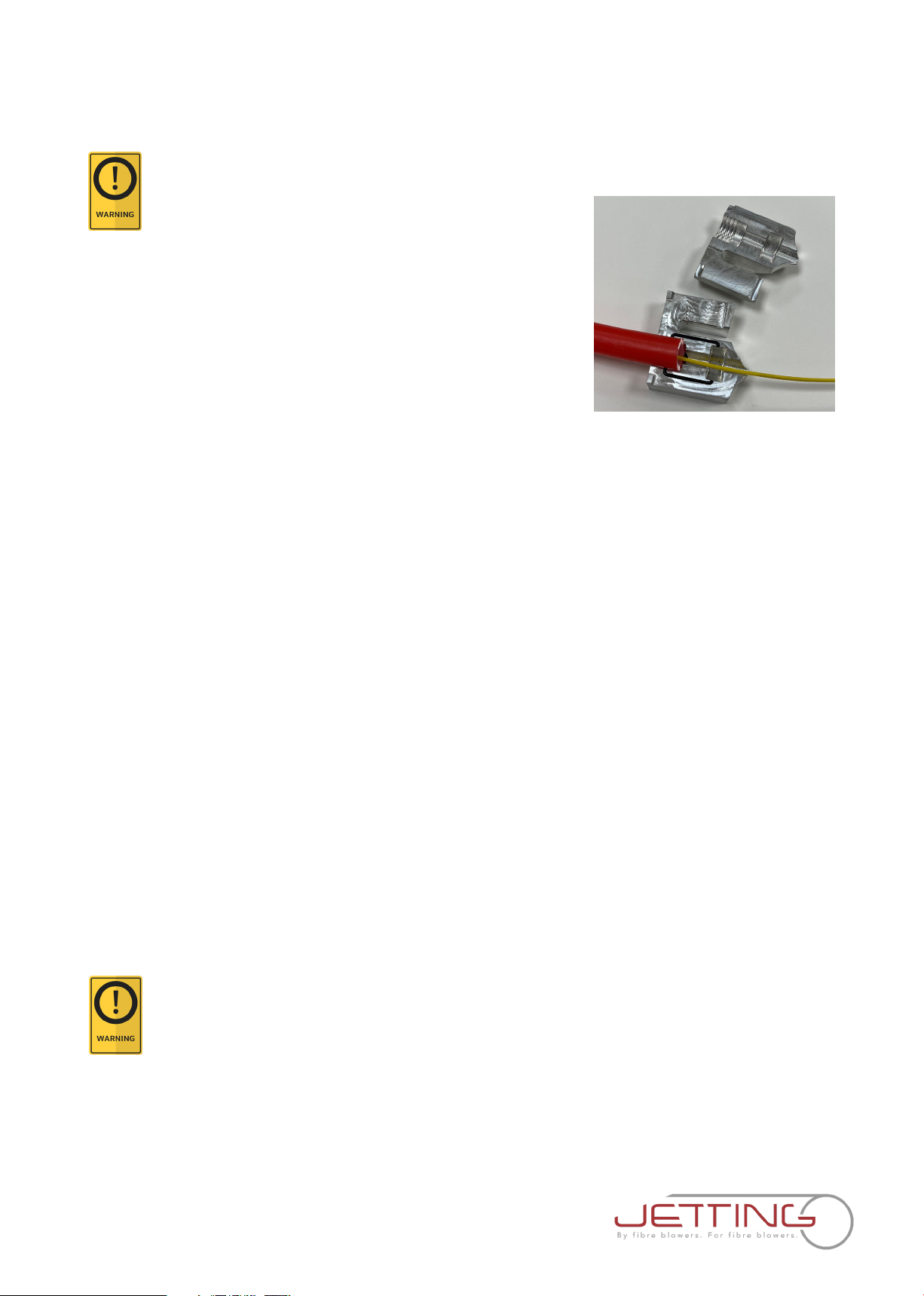
The MJet V0 HD consists of an air block/pipe clamp that is made in two halves that clamp together
around the pipe. The pipe clamp holds a seal that the fiber optic fiber is fed through before entering
the pipe. The pipe clamp and fiber seals can be interchanged to accommodate dierent pipe and
fiber sizes. The pipe is mechanically clamped between the duct clamps at the exit of the pipe clamp,
preventing movement in any direction. Seals conform around the pipe when clamped.
The fiber optic is fed through the pipe by a combined pulling/pushing force. The pulling force is achieved
when pressurized air is fed into the air block and forced into the duct, generating drag on the fiber from
the airflow passing over it. The pushing force is created by engaging the drive wheel system. As the
drive wheel feeds fiber into the pipe, drag force is created by the airflow. The fiber optic floats in the
pipe, minimizing any resistance to being pushed in by the drive wheel.
The use of the MJet V0 HD for operations other than those described in this manual are considered
dangerous and are discouraged. Use of this machine for work other then what is intended, relieves the
manufacturer from any responsibility, civil or penal. The manufacturer's responsibility ceases, and the
warranty is voided when one of the following occurs:
A. When MJet V0 HD is used for purposes other than what is detailed in this manual.
B. Tampering and/or modifications carried out without written approval of the manufacturer.
C. Not using original manufactured replacement parts.
D. Poor maintenance.
E. Not using supplied safety devices or equipment.
F. Connection of this unit to machines and/or parts not produced or authorized in writing by the
manufacturer.
G. The MJet V0 HD should not be used to install any fiber other than optic fiber specified within the
range outlined in this instruction manual.
Jetting AB is not responsible for injuries incurred as a result of improper use of the MJet V0 HD.

2. Technical information
A. Condition of use
1. Temperature from -15° C to +40° C
2. Humidity from 20 % to 90 %
3. Weather conditions relevant to working conditions
4. Natural and/or artificial lighting of the work site, >200 lux
B. Air compressor requirements
1. Pneumatic pressure 16 bar maximum
2. Required air flow 0.14 - 11 m3/min
3. Air hose fittings Cejn type
C. Operational capacities
1. Pushing force 0-200N
2. Pushing speed 0-110 m/min
3. Fiber sizes 0,5 mm to 6,5 mm
4. Pipe sizes 3-16 mm
D. Electrical requirements
1. Power requirements 18 V 4 Ah
2. Power connection Hitachi standard
E. Physical specifications
1. Height 240 mm
2. Length 170 mm
3. Width 120 mm
4. Weight 2,2 kg
F. Wheel drive specifications
1. Maximum pushing force is 200N
2. Adjustable clamp force
G. Pipecoupling requirements
1. Must withstand maximum air pressure of 16 bar
2. Must withstand axial loading and vibration
3. Must be a compression type coupler
4. Must fit snugly
5. Pipe ends must be cut o squarely and deburred
6. Pipe must be fully seated into the coupler

3. Safe operating practices
Read and understand all procedures and safety instructions before using the MJet V0 HD. Observe all
safety information on this page and note specific safety requirements as explained by procedures called
out in this manual. Failure to follow these instructions could result in serious personal injury, property
damage or death.
A. Work area safety
1. Wear personal protective equipment: hard hat, safety glasses, safety shoes, and light leather
work gloves (OSHA approved or personal protective equipment directive 89/686/EEC compliant).
2. Wear close fitting clothing to avoid clothing getting trapped in belt drive.
3. Keep long hair tucked back and refrain from wearing any jewlery.
4. The safe operation of this equipment requires that the operators be on stable footing.
5. Stay clear of fibers or lines under tension.
6. Stay clear of pressurized line and conduit.
7. Use the blower only for its intended purpose.
8. Do not place fiber reel too close to unit. Place the reel far enough away from the unit to ensure
proper control.
9. Keep hands away from belt drive while blower is in operation.
B. Working with air
The MJet V0 HD, using pressurized air to project the fiber at high velocities. Please observe the following
precautions when operating the blower:
1. Forced air creates flying debris. Always wear personal protective equipment.
2. Ensure no personnel are in the destination access vault during the blowing operation.
C. Electrical devices
The motor, controller, and digital display are electrical devices. Electrical shock hazards exist that could
result in severe personal injury or death. Observe the following precautions to avoid electrical hazards:
1. Do not operate in or near water. This includes setting the unit on a wet surface or exposing to rain.
2. Do not operate when there is lightening or extreme weather. An earth stake driven into the ground
as added protection is recommended if there is any chance of extreme weather developing.
3. Do not remove the digital display cover. There are no user-serviceable parts inside.
4. The drive should be switched o before connecting or disconnecting any cords.
5. Important safety Information about batteries and chargers:
• Never submerge the battery in water.
• Never leave the battery in the machine when cleaning.
• If you suspect your lithium battery has water inside do not use or attempt to recharge.
• Never use the charger or battery if the leads, contacts or casings are damaged.
• Dropping the battery may damage the cells or circuit components inside.
• A LITHIUM BATTERY THAT HAS BEEN SUBMERGED IN WATER OR SUSTAINED DAMAGE IS A FIRE
HAZARD. DO NOT USE THE BATTERY. Place outdoors in a noncombustible container well away
from flammable materials. DO NOT RECHARGE THE BATTERY.
• Avoid charging your battery in temperatures below 0 ˚C or exposing the battery to temperatures
below -5 ˚C or above 40 ˚C.

4. Unpacking the box
A. Blower components
Each MJet V0 HD STD Kit contains the following items:
- MJet V0 HD main unit
- 3 pcs driving wheels
- 2 pcs batteries 18 V 4 Ah Lithium batteries
- 110-240 V charger för batteries
- Duct clamps (varying related to order)
- Cable guides (varying related to order)
- Fiber seal kit (varying related to order)
• Do not wrap or cover as the charger generates heat during use.
• Never expose the charger to rain, moisture or damp. If you suspect any of thes have occurred
then do not use the charger.
• Only charge your battery using the compatible Jetting charger provided with your battery.
Never discharge your battery other than in normal use on the MJet V0.
• At the end of the battery’s life, dispose at your local recycling centre.
6. Charging your lithium batteries. Place your battery and charger on a hard level surface and
connect the battery to the charger first before plugging in the mains power. The charger has 2
indicator lights to represent the status of the battery during the charging process. When
connecting a discharged battery, the red light will illuminate to indicate the bulk charge state.
When the bulk charging process is complete, the green light will illuminate. The battery should
be removed from the charger after the green light is active. Never leave the charger connected
to the battery with the mains supply switched o.
We recommend you check/recharge your battery within 24 hours of use. It may take up to 7 hours for
a Lithium battery depending on the capacity of the battery and depth of discharge when
charging. Never leave your battery in a discharged condition for prolonged periods, this will
reduce the life of the battery and your charger may be unable to recharge it. If the battery is not
to be used for a period our advice is to store in a cool, dry place. Please ensure the battery is
fully charged before storing and charge every month thereafter.
D. Working at night requirements
1. Operator must provide portable lighting that achieves a light intensity of at least 200 Lux
(Lumens/m^2).

5. Set up the blower
This manual contains setup and operating instructions for the MJet V0 HD.
Do not connect power supply until setup is complete.
A. Determine fiber size
• Determine fiber size to be installed.
B. Select fiber seal and pipe clamp
• Choose the correct fiber seal and pipe clamp for the
application according to pipe and fiber size.
Choose the smallest possible rear fiber guide.
C. Install fiber seal and fiber in pipe
• Install the appropriate fiber seal on the cable. Once the cable seal is positioned properly on the fiber
you can install the fiber.
D. Install pipe
• Ensure there is adequate length of pipe available to avoid unnecessary strain on the duct.
• Place fiber into pipe, place fiber and seal into the pipe clamp.
• Once the pipe is in place, secure the configuration by installing the top half of the pipe clamp and
pressing firmly together. Close pipe clamp cover and hand tighten the knob to secure.
E. Install fiber in wheel drive and tighten
• Feed the fiber in the wheel drive and through the rear fiber guide.
• Tighten wheel drive using the down screw knob to ensure even pressure on the fiber. Tighten down so
that the wheel no longer slips at the push force setting determined in the crash test procedure. Do not
over tighten.
F. Connect battery to blower
• The power button is on top of the battery connector.
G. Connect air compressor
NOTE: Ensure the air control valve is o before connecting the air hose.
• Attach the air compressor hose to the air compressor if necessary.
• Then connect the compressor hose to the blower unit. The unit uses a standard quick connect air
compressor coupling.
To avoid creating a trip hazard always route
air hose out of the way and secured to a stable object.
The fiber reel should be placed axially perpendicular to the length of micro duct and typically 6ft (2m) or
more from the MJet V0 HD. The MJet V0 HD must be positioned in-line between the fiber to be installed
and the pipe. The fiber should not enter the MJet V0 HD at an angle of more than 10 degrees from the
intended axis of trave.

7. Crash test
Fiber Crash Testing is a very quick and easy step to be completed before attempting the installation of
fiber with the MJet V0 HD. This test is necessary to set the push force control of the motor below the point
that the MJet V0 HD may cause fiber damage as a result of over pushing or encountering an obstruction
in the sub-duct system.
Every fiber has dierent pushing values and these values vary depending on duct I.D.
Always wear protective equipment: hard
hat, safety glasses, safety shoes and work gloves.
IMPORTANT
For the Crash Test to work properly, use the same size fiber and pipe that will be used for the job. Jetting
cannot be responsible for any fiber damages.
Crash Test: For all types of fibers > 0,5 mm diameter
The pushing force is adjusted by pressing the Menu button and set with + and – button. To return to main
screen, hold menu button again.
Please observe: For model V0 HD, the preset pushing force is 15N (but can be adjusted from 6-200N).
6. Display functions

8. Blower operations
1. Verify adjustable push force
Verify adjustable push force is set to the established crash test value and the speed is at minimum.
2. Engage wheel drive
The wheel drive can be operated in forward. For installation, engage the wheel
drive in forward by depressing + button. Install the fiber into the duct using push
only until the installation has slowed.
3. Engage air
Slowly open the air control valve to allow air flow to the air block. Do not apply
maximum air pressure and flow at initial air engagement. Do not open the air
supply before adequate fiber has been pushed in (>100M).
IMPORTANT
Do not exceed 16 bars when operating the unit.
Forced air creates flying debris.
Always wear personal protective equipment.
4. Adjust speed
Use the + and – buttons to adjust the drive speed to ensure smooth installation and match the amount
of air pressure being used so that the forces are working together, not against one another.
5. Install fiber
It may be helpful to guide/apply back tension to the fiber using your hand at the fiber entrance of the
machine to maintain control over the fiber.
1. Set wheel clamp force to the lowest possible setting that will allow for a desirable installation
speed.
2. Insert the fiber and seal inside the pipe clamp as it would be for the actual installation.
3. Install a 1 to 2 m test length of pipe into the MJet V0 HD clamp and insert clamp into the air block.
4. Block the end of the test length of pipe.
5. Tighten the wheel pressure on to the fiber with the wheel drive engaged in the forward direction
until the fiber starts to install.
6. Ram the fiber into the blocked end of the pipe.
7. Wheel should stop in the fiber before the fiber folds over.
8. Reduce the pushing force on the fiber until the wheel stops.
9. Repeat step 6-8 until the fiber folds. This is your push force slip limit.
10. Loosen up the wheel on the fiber a quarter turn and perform test once more to confirm no fold
over has occurred. KEEP THIS SETTING APPLIED TO THE FIBER FOR ACTUAL INSTALLATION!
11. Swap out test length of pipe with actual installation pipe and proceed to operating the
MJet V0 HD.

9. Maintenance
Procedure Daily Weekly Monthly 60 days 90 days
Clean all assemblies and components
thoroughly with dry cloth X
If used in moisture weather. Remove the
machine from the transport box and leave
it to dry completely
X
Check/charge batteries in original charger X
Inspect fasteners and screws X
Check wheels for wear. Replace if excess wear
has occurred. Excessive wear has occurred
when the wheels are no longer able to
eectively grip the fiber optic
X
Duct pack seal replacement X
Change rubber rings on drive wheel Every 50 km unless excessive wear is occurring
Seals replacement Every 10 km unless excessive wear is occurring
Wheel cleaning and tightening Inspect wheel and tighten before and after each use. Clean after each
use, or when necessary
Disconnect power supply and exhaust any air pressure
before servicing any component on the MJET V0 HD.
Avoid handling leaking couplings, valve seal or
inadequately sealed pipe in air block.
DANGER! Risk of air under pressure penetrating skin.
6. Wheel drive engages forward
The wheel drive engages forward by the + button. By the – button the drive wheel will reverse. Please
note that the fiber protection system is disabled in reverse drive.
7. Observe
Set pushing force is reached by 40 % "speed/force %".
8. Disabling fiber protection
To disable the fiber protection system, press and hold “STOP” and “-“ button for 8 seconds. This will be
eective until next reset or power cycle of the machine.
Please observe: With the fiber protection the max. pushing is 200N.
9. Activate fiber protection
To reactivate the fiber protection system, press and hold “STOP” and “+“ button for 8 seconds or switch
on/o the main power supply.

10. Troubleshooting guide
Fiber becomes jammed in the pipe 1. Inform the people at the other end of the pipe that a
problem has been experienced and the operator is
going to shut down the system.
2. Shut o the pneumatic air supply with the air control
valve, allowing the air pressure to be depressurized from
the pipe and the pipe clamp air block.
3. Using the counter or the measurement on the fiber,
determine where the blockage might be located.
4. Notify supervisor about problem and determine a
solution accordingly.
Wheels does not pull the fiber 1. Assist the reel by pushing the fiber of the reel.
The fiber run is hard to restart after 1. Put more air to the system. with the belt drive
having stopped 2. The wheel can be restarted after the air pressure has
increased and stabilized.
Wheel feed does not start 1. Battery is low, check battery meter in the display.
2. Overtemp may have occurred. The display shows
“OVERTEMP” and the motors needs to cool down under
75 degrees Celsius. Do not use compressed air or water to
cool down the machine, just let it wait until it cools down
by itself.

11. EC Declaration of Conformity

12. Notes

MJet V0 HD 18 V USER'S GUIDE AND SAFETY MANUAL
Version 2021-12
Table of contents
Other Jetting Power Tools manuals