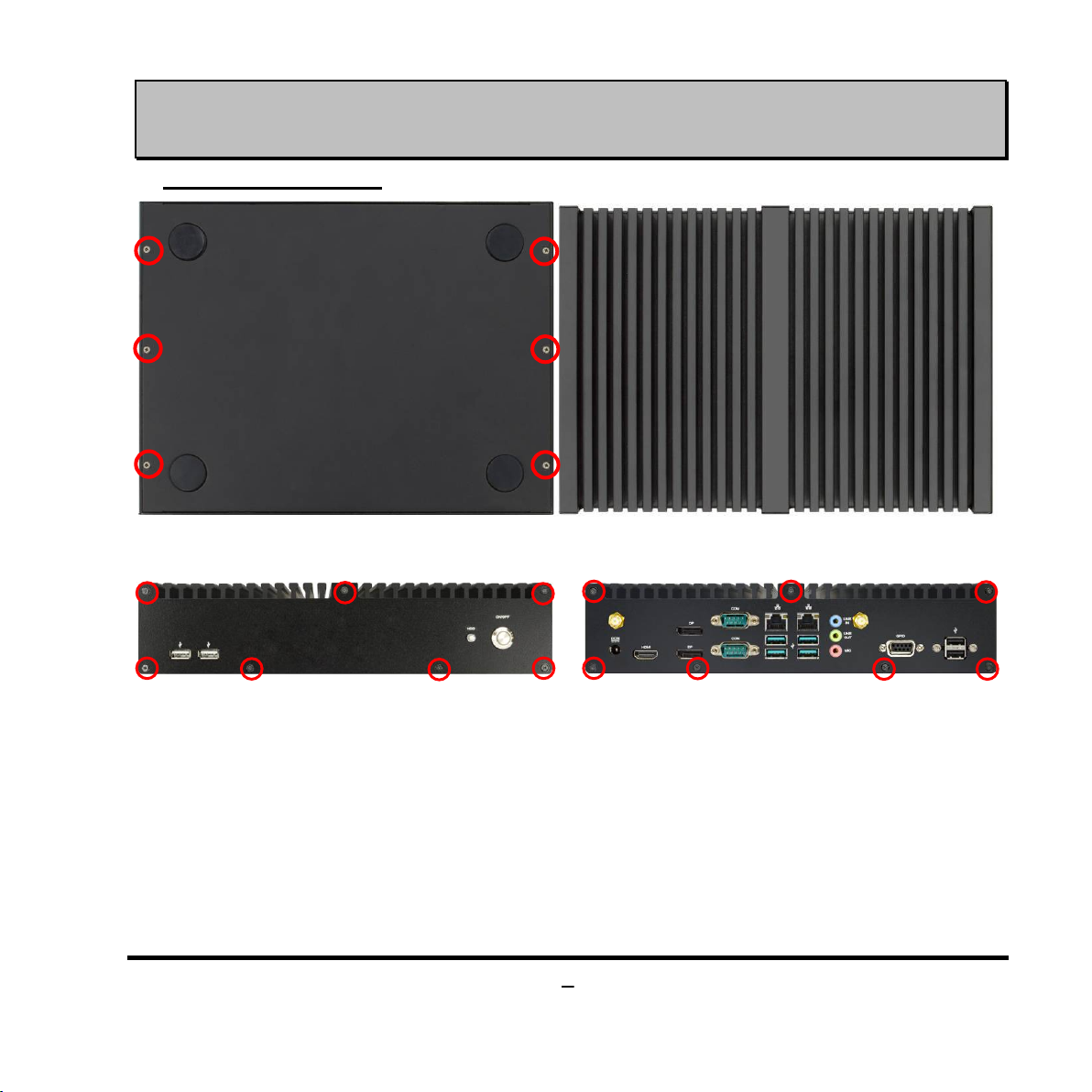
JETWAY JBC501F797 User manual

1
Quick Installation Guide
NO. G03-JC501QIG03-F
Rev: 2.1
Release date: 2021-1-19

2
Notice:
The photos in this file are for illustration purpose only. The model may not be the latest version. Please
refer to the product you purchased for actual specification.
1. To Open the Chassis
1. Locate the screws in the spots marked on the
top cover of the system and unscrew them
one by one.
2. Turn over the barebone system with the
heatsink upwards, as the photo shows.
3. Remove the screws in the marked spots on
the front panel.
4. Remove the screws in the marked spots on
the rear panel.

3
5. Remove the IO panels and lift the cover up to
open the chassis. For user to have a clear
view of layout, we may unplug some of the
cables during installation.
6. For CPU installation, user needs to remove
the screws on the marked spots to dissemble
the motherboard form chassis cover.
Notice: 1. If the system is pre-installed with CPU heatsink, user needs to remove the screws on the
backside of the board to dissemble the heatsink before CPU installation; 2.Make sure that the cables are
plugged into their original places when necessary installation finished for the system to function normally.

4
2. To Install CPU
1. Find CPU socket on the board. Please make
sure that CPU socket is facing towards you
and the level is on you right hand side.
2. Remove the plastic protective cover from the
socket (Put it to the original place if CPU is
not installed. Do not touch the metal contact
point of the CPU socket).
3. Press down the level and move it towards the
right side to free it from the hook.
4. Open the level upwards about 135 degree
and the metal protection plate will be pulled
up at the same time.

5
5. Make sure that Pin-1 Golden Finger Indicator in the place as shown in the above
photo and match the two alignment keys on the CPU with two points of the socket.
CPU can only be correctly installed in this direction. Incorrect installation might
cause damage to CPU.
6. Put down the load plate in the direction shown
above.
7. Press down the load level and move it
leftwards to make sure it is locked under the
notch.
Golden Finger
Indicator
Alignment Key
Alignment Key

6
3. To Install Heatsink Thermal pads
1. Find the above CPU heatsink and CPU thermal pad package. Remove the protective films
on the both sides of the pad and apply it upon the bottom side of the heatsink for better heat
conduction.
2. Place the CPU heatsink upon the
installed CPU. The screw holes of the
heatsink should match corresponding
screw holes of the board. And then apply
corresponding thermal pad to the top
side of the heatsink as the photo shows.
3. Turn the board over and lock the heatsink to the
board by tightening the screws (P/N:
LCSC306M02-F*4) on the marked spots.
Bottom Side
Paste Here!
Top Side
Paste Here!
Tear off the
Protective films
P/N:
HCS3XXHS2-F *1 pcs
20*20*0.5mm
P/N:
HCS310HS1-F*1pcs
60*52*1.0mm
P/N:
LCSC306M02-F*4pcs
(M3 Phillips round-head
brass screw
,
Screw length 6mm
,
Screw tooth length 4.5mm)

7
4. See to it that the silicone gel bars are in their
original places for better heat dispassion and
shockproof before installing the board to the system
cover.
5. Apply corresponding thermal pads to chipset
heat sink. When installation finished, tear off the
protective film from the pads before assembling the
back cover to the chassis.
*Note: There should be one more HCS310HS1-F / HCS3XXHS2-F / HCS501HS2-F left as spare parts
after normal assembly. User can use them to replace corresponding damaged thermal conductive pads.
Notice:Please restore the screws that lock the motherboard to the chassis cover when CPU & heatsink
installation completed. The cables unplugged during this process should be plugged to their original places
after heatsink installation.
P/N:
HCS501HS2-F *1 pcs,
25*25*1 mm

8
4. To Install SO-DIMM to the board
1. Find the SO-DIMM slot on the board for further installation. Open the 2* ejects tabs before SO-DIMM
installation.
2. Adjust compatible SO-DIMM & Press down the SO-DIMM until the golden-finger side fully inserted into
the slot. The eject tabs will lock automatically if installed correctly.
Press Down

9
5. To Install WI-FI Card
Please refer to the following instructions for the installation of the Wi-FI card into M.2
PCIe slot.
1. Locate the M.2. PCIe, type-2230 slot on
the board.
2. Remove the marked screw nut reserved
for M.2 SATA card installation first.

10
3. Insert the gold-figure side of compatible
card into M.2. PCIe slot. See to it that the
golden-figure side is fully inserted into the
slot.
4. Lock the card to the board by tightening up
the screw nut to the marked spot.
5. Locate the reserved Wi-Fi antenna holes on the back panel. Remove the dust-proof
plugs on the marked spots from the panel to install the antenna, as the following details
show.

11
a) Back-side View: Put the metal ring into the antenna head at first, and then push this
antenna head into antenna hole of the rear panel.
b) Front-side View: Put the other washer①into the antenna head, and then lock the
antenna head to the front side of the back panel with the with hexagonal bolt②and
tighten it up.

12
6. The metal hats on the end of the antenna
string are sealed by acetate tape to avoid
possible damage to the system.
7. Tear off the tape to find metal hats of Wi-
Fi antenna string.
8. Press the metal hat on the end of the
antenna string to the antenna slot on the
card as shown.
9. Connect the external Wi-Fi receiver
antenna to the antenna connector on the
rear panel.

13
6. To Install M.2 SATA Card
1. Locate the M.2 SATA slot on the board.
Prepare compatible M.2 SATA or M.2
SSD card. Deferent types of cards come
of different length. Find corresponding
nut location for further installation.
2. Remove the screw and nut fixed at
default location (Skip step 2 & 3 and go
straight to Step 4 if you are going to use
the default position).
3. Remove the screw post fixed at default
location (Skip step 2 & 3 and go straight
to Step 4 if you are going to use the
default position).
4. Lock the screw post into the location
corresponding to the length of the
module.

14
5. Align and insert the gold-figure side of
the compatible M.2 SATA card into the
slot. Make sure that the golden-figure
side is fully inserted into the slot.
6. Lock the card to the board by tightening
up the previously-removed screw nut to
the marked spot.
7. To Install Hard Disk
1. Remove the HDD racks from the cover
by unscrewing the screws in the marked
places.
2. Adjust the HDD and the racks in the
directions as the above photo shows.

15
3. Lock the SATA hard disk to one of the
racks by tightening the screws in the
marked spots.
4. Lock the SATA hard disk to the other
rack by tightening the screws in the
marked spots.
5. Find the compatible SATA cable for the
system in the accessories package.
To connect SATA
hard disk driver.
To connect onboard SATA power connector.
To connect onboard
SATA port.

16
6. Plug this side of the cable to SATA
power-in connector and SATA connector
of the hard disk.
7. Lock the racks with SATA HDD installed
to its original places by tightening the
screws in the marked spots.
8. Plug the other sides of the cables into the SATA power connector and SATA port
connector on the board.
Notice:
When all necessary installations are finished, please make sure that all cables unplugged before
installations are connected to their original places before restoring the back cover to the chassis and
screws on the front panel/back panel/top cover locked to its original places (Refer to Part I). See to it that
the cables inside are not blocked or pressed.

17
8. To Wall Mount the System
1. Install wall mount rack to the system by tightening the screws in the marked positions. Then lock the
other three screws on the other side in the same way.
2. Wall mount the system by tightening two screws in the marked positions. Then tighten up the other
two screws in the marked positions on the other rack.
Table of contents
Other JETWAY Industrial PC manuals