Jireh STIX User manual

STIX
Manual Flange Scanner
DX0022 Rev 01

PAGE i of iv DX0022 Rev 01
SAFETY WARNINGS / PRECAUTIONS
DANGER! The STIX is designed for a specic use. Using the STIX
outside of its intended use could cause damage to the product. Read and
understand this manual before using.
KEEP THIS MANUAL – DO NOT LOSE
THIS MANUAL IS PART OF THE STIX AND MUST BE RETAINED FOR THE LIFE OF THE
PRODUCT. PASS ON TO SUBSEQUENT OWNERS.
Ensure any amendments are incorporated with this document.
WARNING! Can be harmful to pacemaker and ICD wearers. Stay
at least 25 cm (10 in) away.
WARNING! Do NOT operate scanner in an explosive environment.
Do NOT operate scanner in the presence of volatile substances.
The WEEE symbol indicates that the product must not be disposed of as
unsorted municipal waste, but should be collected separately.
(see Disposal on page 31 for additional details).

PAGE ii of iv
Chapter1 Identification 1
1.1. Product Brand 1
1.2. Manufacturer 1
Chapter2 Product Specifications 2
2.1. Intended Use 2
2.1.1. Operating Limits 2
2.1.2. Operating environment 2
2.1.3. User 2
2.2. Unintended Use 3
2.3. Dimensions and Weight 3
2.4. Environmental Sealing 3
2.5. Performance Specifications 4
Chapter3 Definitions 5
3.1. Definition of Symbols 5
Chapter4 System Components 6
4.1. Component Identification 6
4.2. Tools 7
4.2.1. Included Tools 7
4.3.
Flange Scanner Frame 8
4.3.1. Articulated Side Frames 8
4.3.2. Probe Centre Spacing 10
4.4. Dovetail Handle 12
4.5. Brake 13
4.6. Flange Scanner Guides 13
4.7. Magnetic Wheels 15
4.7.1. Wheel Removal 15
4.7.2. Wheel Installation 16
4.8. Frame Bar with Ruler 16
4.9. Spring-Loaded Encoder 17
4.10. Cable Clips 17
4.11. Spring-Loaded Probe Holder 18
4.11.1. Probe Holder Setup 18
TABLE OF CONTENTS

PAGE iii of iv DX0022 Rev 01
4.12.Pivot Buttons 19
Chapter5 Configurations 20
5.1. Two Probe 20
Chapter6 Operation 21
6.1. Setup on a scan surface 21
Chapter7 Maintenance 25
Chapter8 Troubleshooting 26
8.1. Technical Support 26
Chapter9 Spare Parts 27
9.1. Flange Scanner Components 27
9.1.1. Encoder Connector Type 28
9.2. STIX Kit Components 29
9.3. Probe Holder Components 30
9.3.1. Arm Style 30
9.3.2. Pivot Button Style 30
9.4. Variable Components 30
9.4.1. Frame Bars 30
Chapter10 Disposal 31
Chapter11 Limited Warranty 32

PAGE iv of iv

PAGE 1 of 33 DX0022 Rev 01
Chapter 1
IDENTIFICATION
1.1. Product Brand
This user manual applies to the STIX - Flange Scanner which is used for a variety of
flange coupling inspection applications such as flange face corrosion.
1.2. Manufacturer
DISTRIBUTOR:
Jireh Industries Ltd.
53158 Range Road 224
Ardrossan, Alberta, Canada
T8E 2K4
Phone: 780.922.4534
jireh.com
MANUFACTURER:

PAGE 2 of 33
Chapter 2
PRODUCT SPECIFICATIONS
2.1. Intended Use
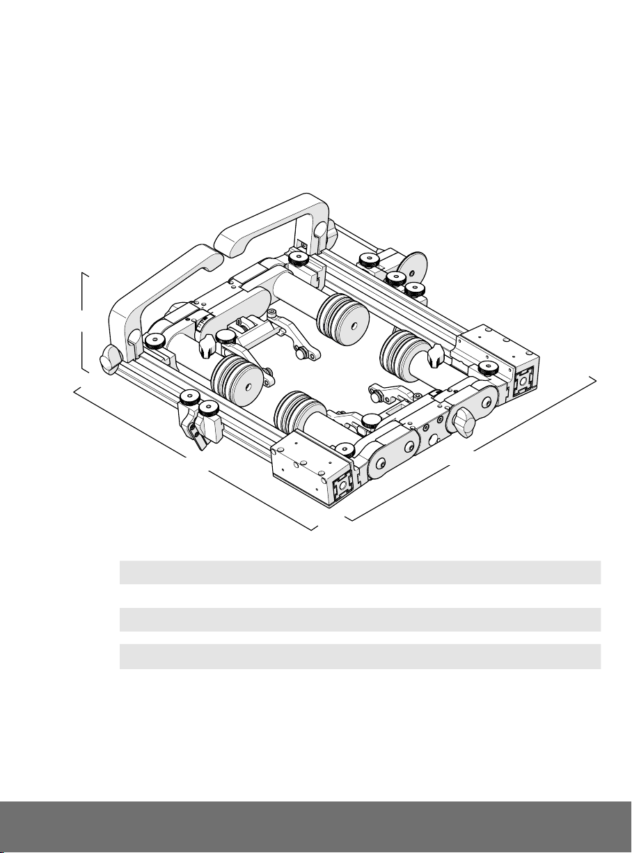
The scanner’s primary purpose is to move an inspection tool over a cylindrical surface
for inspection of flanges.
The intended surface is to:
►be free of excess rust, scale, ferrous debris, ice, frost
►have a minimum OD of 102 mm (3 in) for two probe arrangement
2.1.1. Operating Limits
Minimum Maximum
Flange Range, Outer Diameter: 7.6 cm (3 in) Flat
Radial Scanner Clearance (with handles): 9.7 cm (3.8 in)
Radial Scanner Clearance (without handles): 4.1 cm (1.6 in)
2.1.2. Operating environment
►the scanner is intended for industrial use only
►operating ambient temperature between -20° C (-4° F) and 50° C (122° F).
2.1.3. User
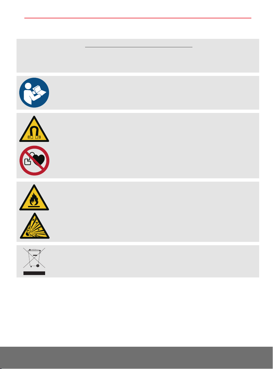
►the scanner is intended to be used by persons who have read and
understand the user manual.
►the scanner is intended to be used by persons without limitations in the
physical abilities of the upper and lower limbs, sight, hearing, or anyone with
a pacemaker

PAGE 3 of 33 DX0022 Rev 01
2.2. Unintended Use
The scanner is not intended for:
►operating in ambient temperatures below -20°C (-4°F) or above 50°C (122°F)
►operation on a surface with a temperature greater than 350°C (662°F)
►use at locations having an explosion or fire hazard
2.3. Dimensions and Weight
A: 10 cm 3.9 in
B: 28 cm 11 in
C: 29.8 cm 11.7 in
Frame Weight: 2.4 kg 5.3 lb
Encoder Cable Length (Standard Kit): 5 m 16.4 ft
2.4. Environmental Sealing
Watertight (not submersible), (contact Jireh Industries Ltd. on page 1 for details)
A
C
B
Fig. 1 - Flange scanner frame dimensions

PAGE 4 of 33
2.5. Performance Specifications
X-Axis Encoder Resolution: 9.05 counts/mm 230.0 counts/inch

PAGE 5 of 33 DX0022 Rev 01
Chapter 3
DEFINITIONS
3.1. Definition of Symbols
Instructions to ‘look here’ or to ‘see this part’.
Denotes movement. Instructing user to carry out
action in a specified direction.
Indicates alignment axis, can also indicate
insertion or movement of parts.
Alerts user that view has changed to a reverse
angle.

PAGE 6 of 33
Chapter 4
SYSTEM COMPONENTS
4.1. Component Identification
Fig. 2 - Flange Scanner Frame
DXA001-
Fig. 3 - Spring-Loaded Encoder
BGS053-
Fig. 4 - Frame Bar with Ruler
BG0090-
Fig. 5 - Irrigation Kit
CMG007
Fig. 6 - STIX Flange Scanner Case
DXA002
Fig. 7 - Magnetic Wheel
BTS031
Fig. 8 - 3/8 in Wrench
EA470
Fig. 9 - 3 mm Hex Driver
EA414
Fig. 10 - Articulated Side Frame Subassembly
DXS001

PAGE 7 of 33 DX0022 Rev 01
4.2. Tools
4.2.1. Included Tools
The 3 mm hex driver (Fig. 11) is sucient for all typical operations and adjustments
of the STIX.
The 3/8 in wrench (Fig. 12) is used to remove and install buttons on the probe
holders.
Fig. 11 - 3 mm hex driver Fig. 12 - 3/8 in wrench

PAGE 8 of 33
4.3. Flange Scanner Frame
4.3.1. Articulated Side Frames
To pivot the articulated
side frames to
accommodate various
diameter sizes, follow
these steps:
1. Loosen the two
black wing knobs
on the sides of the
articulated side frame
(Fig. 13).
2. Pivot the frame bars
or use the handles to
adjust the frame to the diameter required (Fig. 14).
Fig. 13 - Loosen black wing knobs to loosen the flange scanner’s pivot
Fig. 14 - Pivot scanner to appropriate diameter

PAGE 9 of 33 DX0022 Rev 01
3. Observe the diameter
indicators to assist with
setting the scanner to the
correct diameter required
(Fig. 17).
4. Tighten the black wing knobs
(Fig. 16).
5. Place the scanner on the
flange to be inspected
(Fig. 15).
TIP: Use caution when
placing equipment
on the scan surface.
The magnetized
wheels can cause the
flange scanner frame
to lurch towards the
metal suddenly.
Fig. 15 - Place on inspection surface
Fig. 16 - Tighten black wing knob
Fig. 17 - Diameter indicator

PAGE 10 of 33
4.3.2. Probe Centre Spacing
Probe centre spacing is adjusted using these following steps:
1. The articulated side frame operates with a firm friction fit.
2. Slide the one half of the articulated side frame along the frame bars to
achieve the probe spacing required (Fig. 18).
Fig. 18 - Slide the articulated side frame along the frame bar to adjust probe spacing

PAGE 11 of 33 DX0022 Rev 01
3. When probe spacing as been completed (Fig. 19), position the flange
scanner guides as required (see Flange Scanner Guides on page 13).
4. Probe spacing may also be achieved by placing the wedge in alternate
pivot button holes of the probe holder (see Pivot Buttons on page 19).
Fig. 19 - Set probe spacing and configure guides

PAGE 12 of 33
4.4. Dovetail Handle
The dovetail handle oers a means of scanner control. Removal of the dovetail handle
is available to accommodate low profile scanning when required.
1. To reposition or remove the dovetail
handle from the frame bar, Loosen
the dovetail handle’s black wing knob
(Fig. 20).
2. Tighten the black wing knob when the
handle is in place on the frame bar
(Fig. 21).
Fig. 20 - Loosen black wing knob to reposition or remove
Fig. 21 - Tighten black wing knob

PAGE 13 of 33 DX0022 Rev 01
4.5. Brake
Two red knobs activate the system brake and hold the scanner in a required position.
1. Rotate the two red knobs clockwise to activate system braking (Fig. 22).
2. Rotate the two red knobs anti-clockwise to deactivate system braking (Fig. 23).
TIP: When the brake is engaged and the scanner is moved, this may loosen the
wheels from the axle. Grip the magnetic wheel tightly and retighten to the axle
with the 3 mm hex driver (see Magnetic Wheels on page 15).
4.6. Flange Scanner Guides
The guides may be positioned at the centre of the flange to maintain scanner
direction. To utilize the flange scanner guides, follow these steps:
1. Place the scanner on the inspection surface (Fig. 24) and ensure the scanner is
properly aligned with the centre of the flange coupling.
2. Loosen the flange scanner guide knobs (Fig. 25).
Fig. 22 - Activate brake Fig. 23 - Deactivate brake
Fig. 24 - Align scanner on the flange Fig. 25 - Loosen knobs

PAGE 14 of 33
3. Gently press the guides against the
edge of the flange (Fig. 26).
TIP: Ensure flange scanner guides
are not pressed tightly to the
edge of the flange. If positioned
tightly to the flange edge,
scanner movement may be
affected due to the guides
binding and catching on the
flange.
4. Tighten the knobs of the guides
(Fig. 27).
5. Ensure the guides on the both sides of
the scanner are all positioned correctly.
6. It is also possible to position the
guides along the outside of the flange
(Fig. 29). This can be useful when the
guides can not fit between the two
flanges.
Fig. 26 - Position guides against the flange Fig. 27 - Tighten knobs
Fig. 28 - Flange scanner guides positioned
Fig. 29 - Position guides along outside edge of flange

PAGE 15 of 33 DX0022 Rev 01
4.7. Magnetic Wheels
Eight magnetic wheels are included with the system. To install or remove magnetic
wheels, the articulated side frame must be removed (Fig. 30).
4.7.1. Wheel Removal
1. Tightly grip the magnetic wheel
to be removed. Using the 3 mm
hex driver, loosen the magnetic
wheel from the axle (Fig. 31).
2. Repeat step one for the second
magnetic wheel mounted to the
axle.
WARNING! MAGNETIC MATERIAL. The
magnetic wheels produce a magnetic eld which may
cause failure or permanent damage to items such as
watches, memory devices, CRT monitors, medical
devices or other electronics. People with pacemakers or
ICD’s must stay at least 25 cm (10 in) away.
Fig. 30 - Remove probe spacer thingy
Fig. 31 - Wheel removal
Other manuals for STIX
5
Table of contents
Other Jireh Diagnostic Equipment manuals