OPERATING INSTRUCTIONS
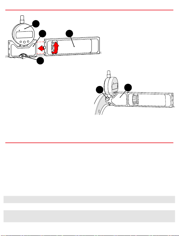
1. Centre Base (Fig. 1-B)
The centre base may be used alone
or in part with multiple extension
arms.
2. Extension Arms (Fig. 1-C)
The extension arms may be used
in any conguration. A small radius
on the bottom surface assists with
measuring small diameter pipes.
3. Blind Side Base (Fig. 2-A)
When the centre base can not be used
appropriately. (i.e. Close to a weld or
flange) Loosen the thumb screw on the
rear of the centre base. Remove the
digital indicator (Fig. 1-A) and mount in
the blind side base. Retighten thumb
screw.
(Fig. 2-B) Additional clearance may be
obtained by rotating the digital indicator 90° before tightening the thumb screw.
An additional indicator tip (Fig. 1-D) has been included in this kit.
PREPARATION FOR USE
4. Setting the Count Direction
The +/- button switches the count direction of display values with respect to the
spindle direction.
5. Setting the Origin
Place gage on a known at surface. Press and hold the ORIGIN button until
0.00 mm (0.0000 in) is displayed. Note: Origin can be set at any spindle position.
6. Reverse Spring Indicator (Optional)
On at surface, depress plunger until needle contacts surface.
Troubleshooting Error Messages
BReplace battery. Note: Origin is cleared when battery is replaced.
CCondensation may have affected the unit. Turn off device and wait 2 hours
for thermal stabilization. If message still appears, return indicator for service.
C
B
D
A
C
B
D
A
Fig. 1
BA
Fig. 2


