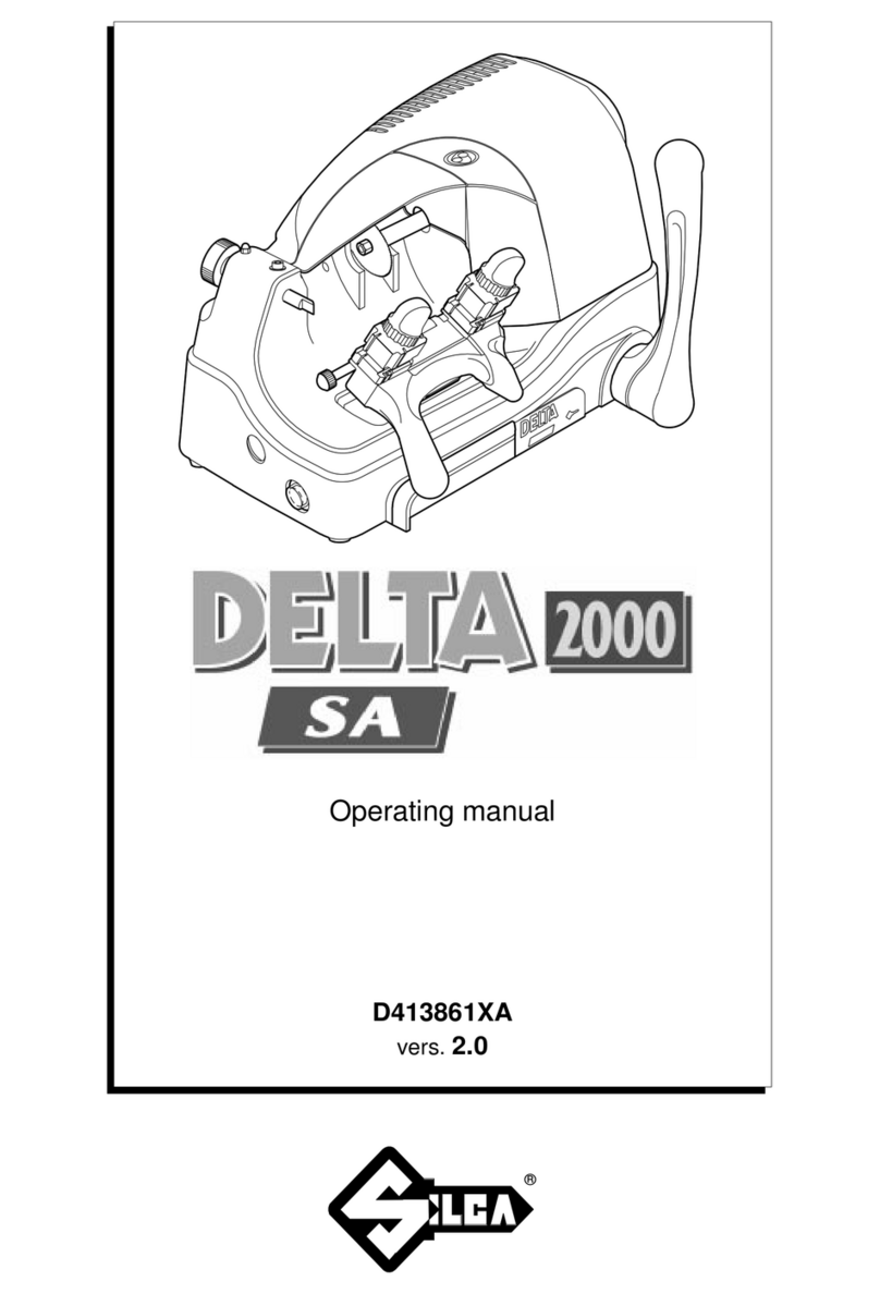
JMA ECCO-AUTOMATIC User manual

MÁQUINA DUPLICADORA ECCO-AUTOMATIC
Manual de instrucciones
ECCO-AUTOMATIC COPYING MACHINE
Instruction manual
KOPIERMASCHINE ECCO-AUTOMATIC
Anweisungshandbuch
MACCHINA DUPLICATRICEECCO-AUTOMATIC
Manuale d’istruzione
MACHINE A TAILLER LES CLES ECCO-AUTOMATIC
Notice d'utilisation
MÁQUINA DUPLICADORA ECCO-AUTOMATIC
Manual de instruções

Indice / Index / Inhaltsverzeichnis / Indice / Index / Indice
1. Presentación y aspectos generales
1.1 Generalidades 4
1.2 Transporte y embalaje 4
1.3 Etiqueta identificadora 4
2. Características de la máquina
2.1 Familia de llaves 4
2.2 Nomenclatura de la llave 4
2.3 Elementos principales de la máquina 4
2.4 Datos tecnicos 4
2.5 Componentes y partes funcionales 5
2.5.1 Accesorios 5
2.5.2 Circuito eléctrico 5
2.5.3 Interruptor de emergencia de parada de la fresa 5
2.5.4 Mordaza de 4 lados 5
3. Operatividad y funcionamiento
3.1 Reglaje máquina 5-6
3.1.1 Control y reglaje Lateral 5
3.1.2 Control y reglaje de la Profundidad de Corte 5
3.1.3 Control y reglaje de los posicionadores 6
3.2Operación de duplicado de la llave 6-7
3.2.1 Duplicado de la llave 6
3.2.2 Duplicado de la llave sin tope 6
3.2.3 Duplicado de la llave cruciforme 7
4. Mantenimiento y seguridad
4.1 Cambio de fresa 7
4.2 Cambio de cepillo 7
4.3 Regulacion de profundidad del carro 7
4.4 Recomendaciones de seguridad 8
4
5-6-7
7-8
4-5
1. Presentation and general aspects
1.1 General aspects 9
1.2 Transport and packaging 9
1.3 Identifying label 9
2. Machine characteristics
2.1 Family of keys 9
2.2 Nomenclature of the key 9
2.3 Main elements of the machine 9
2.4 Technical data 9
2.5 Components and functional parts 10
2.5.1 Accessories 10
2.5.2 Electrical circuit 10
2.5.3 E
mergency switch for stopping the milling cutter
10
2.5.4 4-side clamp 10
3. Effectiveness and operation
3.1 Machine adjustment 10-11
3.1.1 Side control and adjustment 10
3.1.2 Control and adjustment of the depth of cut 11
3.1.3 Control and adjustment of the positioners 11
3.2Key copying operation 11-12
3.2.1 Copying a key 11
3.2.2 Copying a key without a stop 12
3.2.3 Copying a cruciform key 12
4. Maintenance and safety
4.1 Changing the cutter 12
4.2 Changing the brush 12
4.3 Adjusting the depth of the slide 12
4.4 Safety recommendations 13
9
10-11-12
12-13
9-10
1. Vorstellung und grundlegende begriffe
1.1 Allgemeines 14
1.2 Transport und verpackung 14
1.3 Typenschild 14
2. Eigenschaften der maschine
2.1 Schlüsselfamilie 14
2.2 Nomenklatur des schlüssels 14
2.3 Hauptbestandteile der maschine 14
2.4 Technische daten 14
2.5 Komponenten und funktionsbauteile 15
2.5.1 Zubehör 15
2.5.2 Stromkreis 15
2.5.3 Notaus-Schalter zum Anhalten der Fräse 15
2.5.4 Spannbacken (4 seitig 15
3. Betriebsfähigkeit und funktionsweise
3.1 Einstellen der maschin 15-16
3.1.1 Seitliche Steuerung und Einstellung 15
3.1.2 Steuerung und Einstellung der Schneidtiefe 16
3.1.3 Steuerung und Einstellen der Positionierer 16
3.2Kopieren des schlüssels 16-17
3.2.1 Kopieren des Schlüssels 16
3.2.2 Kopieren von Schlüsseln ohne Anschlag 17
3.2.3 Kopieren von Kreuzschlüsseln 17
4. Wartung und sicherheit
4.1 Wechsel des fräsers 17
4.2 Wechsel der bürste 17
4.3 Tiefeneinstellung des schlittens 17
4.4 Sicherheitsempfehlungen 18
14
15-16-17
17-18
14-15
1. Presentazione ed aspetti generali
1.1 Generalita’ 19
1.2 Trasporto ed imballaggio 19
1.3 Etichetta identificativa 19
2. Caratteristiche della macchina
2.1 Famiglie di chiavi 19
2.2 Identificazione chiave 19
2.3 Elementi principali della macchina 19
2.4 Dati tecnici 19
2.5 Accessori e parti funzionali della macchina 20
2.5.1 Accessori 20
2.5.2 Circuito elettrico 20
2.5.3
Interuttore di emergenzaper fermata della fresa
20
2.5.4 Morsetto a 4 lati 20
3. Operativita’ e funzionamento
3.1 Regolazione della macchina 20-21
3.1.1 Controllo e regolazione laterale 20
3.1.2
Controllo e regolazione della profondità del taglio
21
3.1.3 Controllo e regolazione dei posizionatori 21
3.2 Operazione di duplicazione della chiave 21-22
3.2.1 Duplicazione della chiave 21
3.2.2 Duplicazione della chiave senza fermo. 22
3.2.3 Duplicazione della chiave cruciforme 22
4. Manutenzione e sicurezza
4.1 Sostituzione della fresa 22
4.2 Cambio della spazzola 22
4.3 Regolazione della profondita’ del carrello 22
4.4 Raccomandazioni sulla sicurezza 23
19
20-21-22
22-23
19-20

Indice / Index / Inhaltsverzeichnis / Indice / Index / Indice
1. Presentation et aspects generaux
1.1 Generalites 24
1.2 Transport et emballage 24
1.3 Plaque signaletique 24
2. Caracteristiques de la machine
2.1 Familles de cles 24
2.2 Nomenclature de la clé 24
2.3 Eléments principaux de la machine 24
2.4 Donnees techniques 24
2.5 Composants et parties fonctionnelles 25
2.5.1 Accessoires 25
2.5.2 Circuit électrique 25
2.5.3 Interrupteur d’arrêt d’urgence de la fraise 25
2.5.4 Etaux à quatre faces 25
3. Fonctionnement
3.1 Reglage machine 25-26
3.1.1 Contrôle et réglage latéral 25
3.1.2 Contrôle et réglage de la profondeur de la taille 26
3.1.3
Contrôle et réglage des calibres de positionnement
26
3.2 Operatiòns de reproduction de clé 26-27
3.2.1 Reproduction des clés 26
3.2.2 Reproduction de clés sans arrêt 27
3.2.3 Reproduction de clés cruciformes. Face 1 de l’étau 27
4. Maintenance et securite
4.1 Remplacement de la fraise 27
4.2 Remplacement de la brosse 27
4.3 Reglage de l’avancement du chariot 27
4.4 Recommandations de securite 28
24
25-26-27
27-28
24-25
1. Apresentação e aspectos gerais
1.1 Generalidades 29
1.2 Transporte e embalagem 29
1.3 Etiqueta identificadora 29
2. Características da máquina
2.1 Famílias de chaves 29
2.2 Nomenclatura da chave 29
2.3 Elementos principais da máquina 29
2.4 Dados tecnicos 29
2.5 Componentes e partes funcionais 30
2.5.1 Acessórios 30
2.5.2 Circuito eléctrico 30
2.5.3 Interruptor de emergência de paragem da fresa. 30
2.5.4 Mordaça de 4 lados 30
3. Manuseio e funcionamento
3.1 Regulação da máquina 30-31
3.1.1 Control e afinação lateral 30
3.1.2
Controlo e regulação da profundidade de corte
31
3.1.3 Control e regulação dos posicionadores 31
3.2 Duplicação de chaves 31-32
3.2.1 Duplição de chaves 31
3.2.2 Duplição de chaves 32
3.2.3 Duplição de chaves de cruz 32
4. Manutenção e segurança
4.1 Mudança de fresa 32
4.2 Mudança de catrabuxa 32
4.3 Regulação da profundidade do carro 32
4.4 Recomendações de segurança 33
29
30-31-32
32-33
29-30
3

4
Español
Fresa
Cepillo
Guarda fresa
Guarda motor
Mordaza de 4 lados
Manilla de la mordaza
Carro
Manillas del carro
Posicionadores
Limitador avance carro
Palpador
Mando de regulación profundidad del palpador
Tornillo bloqueo palpador
Pulsador de arranque motor/cepillo
Pulsador frontal de arranque del motor
Piloto rojo de encendido
Interruptor de emergencia de parada de la fresa
1
2
3
4
5
6
7
8
9
10
11
Cabeza
Cuello
Tope superior
Tope inferior
Dentado
Paletón
Dorso
Punta
1
2
3
4
5
6
7
8
La máquina ECCO-AUTOMATIC es una duplicadora
automática, robusta y precisa, diseñada para realizar el
duplicado de llaves planas de cerraduras a cilindro, vehí-
culos, llaves cruciformes (en cruz) y especiales.
Ver Figura 2
Generalidades
Presentación
y aspectos generales
1 Características
de la máquina
2
1.1
La máquina duplicadora ECCO-AUTOMATIC ha sido
diseñada teniendo en cuenta las normas de seguridad
vigentes en la C.E.E.
La seguridad del personal involucrado en el manejo
de este tipo de máquinas solo se consigue con un pro-
grama bien diseñado en seguridad personal, como la
implantación de un programa de mantenimiento y el
seguimiento de los consejos recomendados así como el
cumplimiento de las normas de seguridad que contem-
pla este manual.
Aunque la instalación de la máquina no presenta nin-
guna dificultad, es preferible que no intente instalar,
ajustar o manipular la misma sin leer primeramente
este manual.
La máquina sale de nuestra fabrica lista para el uso y
solo necesita operaciones de calibrado para los útiles
que se van a utilizar.
La máquina ECCO-AUTOMATIC se presenta en una caja
de cartón robusta protegida con espuma de embalaje
de las siguientes dimensiones:
Ancho = 570 mm, largo = 520 mm, alto = 410mm
Peso máquina más embalaje = 22 Kg.
Cuando desembale la máquina, inspecciónela cuidado-
samente por si hubiese sufrido algún daño en el trans-
porte. Si encuentra alguna anomalía, avise inmediata-
mente al transportista y no haga nada con la máquina
hasta que el agente del transportista haya realizado la
inspección correspondiente.
Para el desplazamiento de la máquina de un lugar a
otro, aconsejamos que coja la máquina sólo por su base
y no por otras partes.
La máquina duplicadora ECCO-AUTOMATIC está pro-
vista de la etiqueta identificadora, con especificación
del número de serie o matrícula de máquina, nombre y
dirección del fabricante, marca CE y año de fabricación.
Ver figura 1.
Etiqueta identificadora
1.3
Los principales datos técnicos se reflejan a continuación:
Motor: Monofásico 220V, 50Hz, 0.18Kw, 1350 rpm, 1.7 A.
o Monofásico 110V, 60Hz, 0.18Kw, 1700 rpm, 3.14 A.
Fresa: Acero extra rápido (HSS) Δ63 x 16 x 5 mm.
Velocidad giro fresa: 1.350 rpm.
Mordazas: De acero, y con 4 lados de amarre.
Desplazamiento del carro: De forma automática, sobre coji-
netes autolubricados, y accionado mediante motorreductor
y excéntrica.
Curso útil: Eje X= 43 mm. = máxima longitud de cifrado.
Dimensiones: Ancho = 470 mm, Profundidad = 245 mm, Alto =
280 mm.
Peso: 22 Kg.
Datos técnicos
2.4
Transporte y embalaje
1.2
Elementos principales de la máquina
2.3
Nomenclatura de la llave
2.2
Familia de llaves
2.1
La máquina ECCO-AUTOMATIC duplica los siguientes
tipos de llaves:
- Llaves planas.
- Llaves de vehículos.
- Llaves cruciformes.
12
13
14
15
16
17

Español
5
Español
2.5.2 Circuito eléctrico Ver Figura 4
Los componentes principales del circuito eléctrico
y electrónicos son los siguientes:
Toma de corriente
Disyuntor
Motor
Motorreductor
Microinterruptores
Pulsador frontal (duplicación)
Pulsador lateral izquierdo (cepillo)
Piloto rojo
Interruptor de emergencia (parada de la fresa)
Operatividad
y funcionamiento
3
Componentes y partes funcionales
2.5 Reglaje máquina
3.1
Llaves fijas de 18.
Llaves para el reglaje lateral y profundidad de
la máquina.
Calzos para el tope punta de la llave.
Calzos con rebaje para el duplicado de la llave
cruciforme.
Juego de llaves allen (2, 2.5, 3, 4, 5).
Varillas de Δ1,20
Varillas de Δ1,70
2.5.1 Accesorios Ver Figura 3
4
5
1
2
3
1
2
3
4
2.5.3 Interruptor de emergencia de parada de la fresa
Ver figura 5
Esta máquina duplicadora por el hecho de ser automática
y con el fin de evitar accidentes, dispone de un interruptor
de emergencia situado en su parte frontal-derecha.
En caso de urgente necesidad, enclavar este interruptor
para detener el giro de la fresa. La fresa se detiene instan-
táneamente, pero el carro sigue avanzando hasta comple-
tar su ciclo de cifrado.
En el supuesto en el que el carro encontrase en su cami-
no algún obstáculo, el motor que lo acciona notaría una
fuerza extra necesaria para poder mover el carro, y se
detendría. Al retirar el obstáculo, el carro proseguiría su
camino.
NOTA: Mientras el interruptor de emergencia continúe
enclavado, la fresa no podrá girar (ni iniciando un ciclo de
cifrado, ni pulsando el pulsador que acciona el cepillo). Por
lo tanto, y si se quiere volver a utilizar la máquina (con giro
de la fresa incluido), hay que desenclavar el interruptor de
emergencia.
3.1.1 Control y reglaje lateral
•Amarrar las llaves de reglaje (2) en la cara nº1 de
las mordazas, realizando el tope contra las chapas
de tope punta (3) (introducidas éstas, en la ranura
situada más hacia la dcha.).
•Desbloquear el carro y acercar las mordazas al
índice copiador (I) y a la fresa (F). Para realizar este
punto, hay que seguir los siguientes pasos:
- Iniciar el ciclo de cifrado.
- Cuando el palpador toque el paletón de la llave,
apagar la máquina accionando el interruptor
general que posee en su parte trasera.
- En este momento, y por seguridad, desconectar el
cable de alimentación.
•Acercar las mordazas con las llaves de reglaje (2)
hacia el índice copiador (I) y la fresa (F), de forma
que las llaves de reglaje estén en posición correcta
con el índice copiador y la fresa.
•En el caso de no coincidir debidamente las muescas
de las llaves de reglaje con el índice copiador y con
la fresa, actuar de la siguiente manera:
- Aflojando ligeramente los prisioneros (T) del eje,
tenemos la posibilidad de desplazar la fresa a dere-
cha o izquierda. Debemos desplazar la fresa hasta
una posición en la cuál, coincida sobre la muesca
de la llave de reglaje correspondiente. Para realizar
esta operación es necesario soltar previamente el
guarda del motor.
- La distancia queda regulada, coincidiendo el índice
copiador (I) y la fresa (F) en los respectivos rebajes
de las llaves de reglaje. Amarrar los prisioneros (T)
del eje.
•Finalmente, desplazar manualmente el carro hasta
su posición más extrema de la izda., y bloquearlo,
presionándolo hacia abajo. Volver a accionar el
interruptor general de la máquina. Tener mucho
cuidado, ya que al volver a accionar este interrup-
tor, la máquina se pondrá en funcionamiento ins-
tantáneamente, hasta completar el ciclo de cifrado
que había iniciado antes de apagar la máquina.
Ver Figura 8
NOTA: Después de un Reglaje Lateral, siempre se realizará
un Reglaje de los Posicionadores.
6
7
5
6
7
8
9
En la duplicadora ECCO-AUTOMATIC, existen tres
tipos de regulación (Lateral, Profundidad de Corte y
Posicionadores).
La maquina se entrega con los 3 reglajes realizados, ya
que se determinan en la fase de montaje de la máquina.
Excepcional será la vez que la duplicadora precise de un
Reglaje Lateral o de un Reglaje de los Posicionadores. En
cambio, con cada cambio de fresa deberá realizarse un
Reglaje de la Profundidad de Corte, para garantizar un
resultado óptimo en la calidad del duplicado.
3.1.2 Control y reglaje de la profundidad de corte
•Amarrar las llaves de reglaje (2) en la cara nº1 de
las mordazas, realizando el tope contra las chapas
de tope punta (3) (introducidas éstas, en la ranura
situada más hacia la dcha.).
2.5.4 Mordaza de 4 lados
La mordaza está diseñada para amarrar distintas fami-
lias de llaves en cada lado. En la figura se indican las
posibilidades de duplicado en cada uno de los lados de
la mordaza.
1) El duplicado de la llave con apoyo en el dorso:
Lado 1: Llaves con paletón normal.
Lado 2: Llaves con paletón estrecho.
2) El duplicado de la llave mediante amarre en la
guía (perfil):
Lado 3: Llaves con guía en la parte inferior.
Lado 4: Llaves con guía en la parte superior.
Ver figura 6
3) El duplicado de la llave tipo NEIMAN, median-
te amarre en la guía.
Ver figura 7

6
Español
¡CUIDADO!: Cuando se utilice correctamente, la duplica-
dora ECCO-AUTOMATIC es una máquina absolutamente
segura; sin embargo, no se puede olvidar que el ciclo de
trabajo es automático y no ocupa las manos del operador.
Operación de duplicado de la llave
3.2
3.2.1 Duplicado de la llave
•Girar las mordazas, para localizar el lado correcto
de bloqueo de la llave según el tipo de llave a
duplicar.
•Tanto la llave original como la llave en bruto a
duplicar, deberán introducirse por la parte izquier-
da de las respectivas mordazas.
•Introducir la llave original en la mordaza izda. y
la llave en bruto a duplicar en la mordaza dcha.,
asegurándose de:
- Apoyar el tope de la llave contra el posicionador.
- Apretar la mordaza, manteniendo el dorso de la
llave debidamente apoyado sobre la base de la
mordaza.
•Retirar los posicionadores.
•Desbloquear el carro presionándolo hacia abajo, y
arrastrarlo en esta posición, hasta el extremo dere-
cho. En esta posición, soltar el carro suavemente.
•Pulsar al mismo tiempo (durante unos 3 segundos)
los dos pulsadores de puesta en marcha. Estos
pulsadores de puesta en marcha son: El que se
encuentra en el lateral izdo. de la máquina, y el que
se encuentra en la parte frontal de la misma.
•Comenzará el ciclo de duplicado. Este ciclo dura
aproximadamente 30 segundos.
•Al final del ciclo de duplicado, la fresa y el carro se
paran automáticamente.
•Volver a bloquear el carro en su posición de reposo,
presionándolo para ello hacia abajo, y soltándolo
posteriormente de forma suave.
•Soltar las llaves de las mordazas.
•Activar el cepillo mediante el pulsador del lateral
izdo., para eliminar las rebarbas.
NOTA: El piloto frontal rojo siempre está encendido y seña-
la que la duplicadora está alimentada.
NOTA: Para un óptimo funcionamiento de la máquina, es
aconsejable sustituir la fresa cuándo está desgastada (desa-
filada). Hay que tener en cuenta que el tiempo de duración
de la fresa depende de varios factores (principalmente, del
material de las llaves que se cifran), pero como orientación
podemos decir que la duración de la fresa se estima en unas
5.000 llaves cifradas.
•Desbloquear el carro y acercar las mordazas al
índice copiador (I) y a la fresa (F). Para realizar este
punto, hay que seguir los siguientes pasos:
- Iniciar el ciclo de cifrado.
- Cuando el palpador toque el paletón de la llave,
apagar la máquina accionando el interruptor gene-
ral que posee en su parte trasera.
- En este momento, y por seguridad, desconectar el
cable de alimentación.
•Acercar las mordazas con las llaves de reglaje (2)
hacia el índice copiador (I) y la fresa (F), de forma
que las llaves de reglaje se apoyen sobre el índice
copiador y la fresa.
•Girar la fresa con la mano. Si la fresa roza ligera-
mente la llave de reglaje, la máquina está debida-
mente regulada.
•Si al girar la fresa, ésta lo hace libremente; sin rozar,
nos indica que la fresa está retrasada con respecto
al palpador y el fresado es insuficiente. Por el con-
trario, si la fresa queda bloqueada en la llave de
reglaje, nos muestra que la fresa está adelantada
con respecto al palpador y el fresado es excesivo.
Ver figura 9
3.1.3 Control y reglaje de los posicionadores
•La cara izda., del posicionador del lado dcho. (P2),
debe coincidir con la cara izda. de la fresa (F),
cuando el carro se encuentra en su posición más
extrema hacia el lado dcho.; estas caras de la fresa
y del posicionador, determinan el inicio del ciclo
de duplicado en la llave. Para realizar este ajuste,
seguir los siguientes pasos:
- Apagar la máquina accionando el interruptor
general que posee en su parte trasera.
- Desbloquear el carro y desplazarlo manualmente
hasta el extremo derecho. En esta posición, soltar
suavemente el carro.
- Apoyando la chapa de tope punta (2) en la cara
izda. de la fresa (F), la cara izda. del posicionador
(P2), debe coincidir también con la chapa de tope
punta (2).
- Si esto no ocurre, soltar el prisionero (T2) que
amarra el posicionador (P2), y volver a amarrarlo
en su posición correcta.
•La distancia entre el posicionador del lado dcho.
(P2) y el posicionador del lado izdo. (P1), debe
coincidir con la distancia entre la fresa (F) y el índice
copiador (I). Por lo tanto, para realizar este ajuste,
seguir los siguientes pasos:
- Mantener la máquina apagada, y el carro en su
posición extrema hacia el lado dcho.
- Apoyando la chapa de tope punta (2) en la cara
izda. del índice copiador (I), la cara izda. del
posicionador (P1), debe coincidir también con la
chapa de tope punta (2).
- Si esto no ocurre, soltar el prisionero (T1) que
amarra el posicionador (P1), y volver a amarrarlo
en su posición correcta.
•Por último, volver a enganchar el carro en su posi-
ción de reposo.
Ver figura 10
Por consiguiente, si el duplicador acercase involuntariamen-
te las manos a la zona de trabajo de la máquina, puede
haber riesgos de aplastamiento y de corte.
En caso de urgente necesidad, enclavar el interruptor de
seguridad para detener el giro de la fresa.
¡CUIDADO!: Para trabajar en condiciones de seguridad
total durante las distintas fases de la duplicación, siga estas
indicaciones:
• Trabajar con las manos secas.
• El guarda fresa tendrá que estar puesto en cualquier ope-
ración de duplicado.
• Uso de gafas protectoras.
• Asegúrese de que la máquina está conectada a tierra.
• No acercar la mano a la fresa en movimiento.
• Poner en marcha la máquina solo cuando se terminen las
operaciones con el carro (amarrar llave en la mordaza, etc)
Español
7
Español
3.2.2 Duplicado de la llave sin tope
•Introducir los dos calzos (2), en una de las ranuras
verticales (R) de cada mordaza, en función de la
longitud de la llave a duplicar.
•Apoyar las puntas de las llaves contra los calzos (2).
Las llaves quedan así regladas.
•Por último, apretar las mordazas y retirar los calzos
(2).
•Antes de iniciar el ciclo de cifrado, verificar que el
inicio del dentado de la llave quede al lado dcho.
de la punta del palpador (para asegurarnos de que
se van a duplicar todos los dientes de la llave), y que
la cabeza de la llave quede al lado izdo. de la punta
del palpador (para asegurarnos de que no existirá
una colisión indeseada entre la cabeza de la llave y
la punta del palpador).
Ver figura 11
3.2.3 Duplicado de la llave cruciforme
• Este tipo de llave se duplica en el lado 1 de la
mordaza.
• Las llaves siempre deben ser introducidas en las
mordazas, de izquierda a derecha.
• Introducir los dos calzos (5), con la abertura o
rebaje hacia arriba, en una de las ranuras verticales
(R) de la mordaza, en función de la longitud de la
llave a duplicar.
• Apoyar los topes de las llaves contra los calzos (5).
Las llaves quedan así regladas.
• Por último, apretar las mordazas y retirar los calzos
(5).
• El cifrado de la llave se realiza en tres operaciones,
girando y apoyando cada vez el tope de la llave
contra el calzo (5).
• Antes de iniciar el ciclo de cifrado, verificar que el
inicio del dentado de la llave quede al lado dcho.
de la punta del palpador (para asegurarnos de que
se van a duplicar todos los dientes de la llave), y que
la cabeza de la llave quede al lado izdo. de la punta
del palpador (para asegurarnos de que no existirá
una colisión indeseada entre la cabeza de la llave y
la punta del palpador).
Ver figura 12
A la hora de ejecutar cualquier operación de manteni-
miento, es necesario cumplir los requisitos:
Mantenimiento
y seguridad
4
Cambio de fresa
4.1
Nunca se debe efectuar ninguna operación con la
máquina en marcha.
Se debe desconectar el cable de la conexión eléctrica.
Se han de seguir estrictamente las indicaciones del
manual.
Utilizar piezas originales de repuesto.
3
1
2
4
Para cambiar la fresa actuar de la siguiente manera:
Apagar la máquina del interruptor general y desconec-
tar el cable de alimentación.
Aflojar los dos prisioneros del guarda fresa, y retirarlo
momentáneamente.
Con ayuda de las dos llaves fijas de 18, bloquear el eje
de la fresa y soltar la tuerca (K) –rosca izquierda- que
amarra la fresa (F).
Seguidamente sustituir la fresa, y finalmente volver a
colocar el guarda fresa.
Después de un cambio de fresa, siempre es recomen-
dable realizar un reglaje lateral y de profundidad en
la duplicadora.
3
1
2
4
5
Cambio de cepillo
4.2
Para cambiar el cepillo actuar de la siguiente manera:
Apagar la máquina del interruptor general y desco-
nectar el cable de alimentación.
Aflojar los dos prisioneros del guarda fresa, y retirarlo
momentáneamente.
Con ayuda de una llave fija de 18, bloquear el eje de
la fresa y soltar el tornillo (R) con ayuda de una llave
allen.
Seguidamente sustituir el cepillo, y finalmente volver
a colocar el guarda fresa.
Ver figura 13
3
1
2
4
Regulacion de profundidad del carro
4.3
Esta regulación sirve para proteger las mordazas contra
posibles colisiones con el palpador y la fresa.
La distancia entre la fresa-palpador y las mordazas, debe
ser de unos 0,15 mm. En caso de que esta distancia se vea
modificada, actuar de la siguiente manera:
•Desbloquear el carro y acercar las mordazas al pal-
pador y a la fresa. Para realizar este punto, hay que
seguir los siguientes pasos:
- Colocar una llave cualquiera en la mordaza del
lado izdo., e iniciar el ciclo de cifrado.
- Cuando el palpador se encuentre más o menos en
la mitad del paletón de la llave, apagar la máqui-
na accionando el interruptor general que posee
en su parte trasera.
- En este momento, y por seguridad, desconectar el
cable de alimentación.
- Retirar la llave que teníamos amarrada en la
mordaza izda.
•Aflojar ligeramente el prisionero de bloqueo (Z),
con ayuda de una llave tipo allen.
•Haciendo girar en sentido horario o antihorario el
prisionero de tope (W), se consigue alejar o acercar
las mordazas a la fresa y palpador.

8
Español
No intente arrancar o manipular la máquina hasta
que todos los temas de seguridad, instrucciones para
la instalación, guía del operario y procedimientos
de mantenimiento, hayan sido cumplimentados y
entendidos.
Desconecte siempre el suministro eléctrico,
antes de realizar cualquier trabajo de limpieza o
mantenimiento.
Mantenga siempre limpia la máquina así como su
entorno.
Se tiene que trabajar con las manos secas.
Se tienen que usar gafas de protección, aunque la
máquina tenga protección.
Asegúrese de que la máquina tenga toma a tierra.
En caso de urgente necesidad, enclavar el interruptor de
emergencia para detener el giro de la fresa.
Recomendaciones de seguridad
4.4
3
1
2
4
5
6
7
•Una vez realizado el ajuste de la distancia, volver a
bloquear el espárrago de tope (W) por medio del
espárrago de bloqueo(Z).
•Finalmente, desplazar manualmente el carro hasta
su posición más extrema de la izquierda, y blo-
quearlo, presionándolo hacia abajo. Volver a accio-
nar el interruptor general de la máquina. Tener
mucho cuidado, ya que al volver a accionar este
interruptor, la máquina se pondrá en funciona-
miento instantáneamente, hasta completar el ciclo
de cifrado que había iniciado antes de apagar la
máquina.
Ver figura 14

99
English
Cutter
Brush
Cutter guard
Motor guard
4-side clamp
Clamp handle
Slide
Slide handles
Positioners
Slide advance limiter
Feeler
Depth adjustment command of the feeler
Feeler blocking screw
Motor/brush start-up push-button
Motor start-up front push-button
Red ignition pilot light
Emergency switch for stopping the milling cutter
1
2
3
4
5
6
7
8
9
10
11
Head
Neck
Upper stop
Lower stop
Notching
Bit
Blade
Tip
1
2
3
4
5
6
7
8
The ECCO-AUTOMATIC is an automatic copying machine
that is both robust and precise. It is designed to dupli-
cate flat keys of cylinder locks, car keys, and cruciform
(cross-shaped) and special keys.
See figure 2
General aspects
Presentation
and general aspects
1 Machine
Characteristcis
2
1.1
The ECCO-AUTOMATIC copying machine has been desig-
ned taking current EEC safety regulations into account.
The safety of the personnel involved in the handling
of this type of machines can only be achieved with a
well-designed personal safety programme. This involves
the introduction of a maintenance programme and the
following of certain recommendations, together with
compliance with the safety regulations mentioned in
this manual.
Although the installation of the machine is straig-
htforward, we recommend that you should not try to
install, adjust, or handle it without first reading this
manual.
The machine leaves the factory ready for use; it only
needs to be calibrated for the use that it will be given.
The ECCO-AUTOMATIC machine is presented in a tough
cardboard box, protected by packing foam, of the follo-
wing dimensions:
Width = 570 mm, length = 520 mm, height = 410 mm
Weight of the machine plus packaging = 22 Kg.
When you unpack the machine, inspect it carefully in
case it has been damaged in transit. If you find any
anomaly, notify the haulier immediately and do not
touch the machine until the haulier’s agent has carried
out the corresponding inspection.
To move the machine from one place to another, we
advise you to lift the machine only by its base.
The ECCO-AUTOMATIC copying machine has the follo-
wing identifying label specifying the serial number or
number plate of the machine, the name and address of
the manufacturer, the EC mark, and the year of manu-
facture. See figure 1
Identifying label
1.3
The main technical data are quoted below:
Motor: Single-phase 220V, 50Hz, 0.18Kw, 1350 rpm, 1.7 A.
or Single-phase 110V, 60Hz, 0.18Kw, 1700 rpm,
3.14 A.
Cutter: High speed steel (HSS) Δ63 x 16 x 5 mm.
Cutter turning speed: 1,350 rpm.
Clamps: Of steel with 4 trunnion sides.
Displacement of the slide: Automatic, on self-lubricating
bearings, and activated by an off-centre motor-reducer.
Actual run: Axis X = 43 mm. = maximum copying length.
Dimensions: Width = 470 mm, depth = 245 mm, height =
280 mm.
Weight: 22 Kg.
Technical data
2.4
Transport and packaging
1.2
Main elements of the machine
2.3
Nomenclature of the key
2.2
Family of keys
2.1
The ECCO-AUTOMATIC machine copies the following
types of keys:
- Flat keys.
- Car keys.
- Cruciform keys.
12
13
14
15
16
17

10
English
2.5.2 Electrical circuit See figure 4
The main components of the electrical and elec-
tronic circuits are as follows:
Current collector
Circuit breaker
Motor
Motor-reducer
Microswitches
Front push-button (copying)
Left-hand side push-button (brush)
Red pilot light
Emergency switch for stopping the milling
cutter
Effectiveness
and operation
3
Components and functional parts
2.5 Machine adjustment
3.1
18-size fixed spanners
Spanners for lateral and depth adjustment of
the machine
Wedges for the tip stop of the key
Wedges with notches for copying cruciform
keys
Set of Allen keys (2, 2.5, 3, 4, 5).
Rods of Δ1.20
Rods of Δ1.70
2.5.1 Accessories See figure 3
4
5
1
2
3
1
2
3
4
3.1.1 Side control and adjustment
•Secure the adjustment keys (2) on face no. 1 of the
clamps, going as far as the tip stop plates (3) (with
these inserted into the groove located further to
the right).
•Unblock the slide and bring the clamps near to the
copying index (I) and the cutter (F). To do this, the
steps below must be followed:
- Start the cutting cycle.
- When the feeler touches the bit of the key, turn
off the machine by activating the general switch
located at the back.
- At this point, unplug the power cable as a safety
measure.
•Bring the clamps with the adjustment keys (2)
towards the copying index (I) and the cutter (F), in
such a way that the adjustment keys are correctly
positioned regarding the copying index and the
cutter.
•If the notches of the adjustment keys do not duly
coincide with the copying index and the cutter,
proceed as follows:
- By loosening slightly the studs (T) of the axis we
can move the cutter to the right or to the left.
The cutter should be moved to a position in which
it coincides on the notch of the corresponding
adjustment key. To carry out this operation it is
necessary to release the motor guard in advance.
- The distance is thus adjusted, with the copying
index (I) and the cutter (F) coinciding in the res-
pective rebates of the adjustment keys. Secure
the studs (T) of the axis.
•Finally, move the slide manually towards the fur-
thest position on the left, and block it by pressing
downwards. Activate the general machine switch
again. Take great care, as when this switch is activa-
ted again the machine will start up instantaneously
until the cutting cycle that had been started before
turning off the machine is completed.
NOTE: After a lateral adjustment, an adjustment of
the positioners is always carried out.
See figure 8
6
7
5
6
7
8
9
The ECCO-AUTOMATIC copying machine has 3 types of
adjustment (Lateral, Depth of cut, and Positioners).
The copying machine is supplied with three adjustments
having been carried out, as these are determined during
the assembly stage of the machine. Only in exceptional
cases will the machine need a lateral adjustment or an
adjustment of the positioners. In contrast, each time
the cutter is changed a depth of cut adjustment must
be carried out if optimum copying quality is to be gua-
ranteed.
3.1.2 Control and adjustment of the depth of cut
•Secure the adjustment keys (2) on face no. 1 of the
clamps, going as far as the tip stop plates (3) (with these
inserted into the groove located furthest to the right).
•Unblock the slide and bring the clamps nearer to the
copying index (I) and the cutter (F). To do this, the steps
below must be followed:
- Start the cutting cycle.
2.5.3 Emergency switch for stopping the milling cutter
See figure 5
To prevent accidents, this automatic key-cutting machine is
equipped with an emergency switch, located on the front
right part of the machine.
In case of emergency, block this switch to stop the cutter
from turning. The cutter will stop immediately, although
the slide will continue to move forward until it has finished
the coding cycle.
If the slide should hit an obstacle, the motor controlling it
will require extra power to move the slide, and the slide
will stop. It will continue working when the obstacle is
removed.
NOTE: While the emergency switch is blocked, the milling
cutter cannot be turned (by starting a coding cycle or by
pressing the button that works the plane). If you wish to
continue using the machine (turning the milling cutter),
the emergency switch must therefore be unblocked.
2.5.4 4-side clamp
The clamp is designed to secure different families of
keys on each side. The figure shows the copying possi-
bilities on each of the sides of the clamp.
1) The copying of a key with support on the
blade:
Side 1: Keys with normal bit.
Side 2: Keys with narrow bit.
2) The copying of a key by trunnion on the guide
(profile):
Side 3: Keys with a guide on the lower part.
Side 4: Keys with a guide on the upper part.
See figure 6
3) The copying of NEIMAN-type keys by trunnion
on the guide.
See figure 7

1111
English
- When the feeler touches the bit of the key, turn off
the machine by activating the general switch located
at the back.
- At this point, unplug the power cable as a safety mea-
sure.
•Bring the clamps with the adjustment keys (2) towards the
copying index (I) and the cutter (F), in such a way that the
adjustment keys rest on the copying index and the cutter.
•Turn the cutter by hand. If it touches the adjustment key
slightly, the machine is correctly adjusted.
•If when the cutter is turned it moves freely without
touching anything, this indicates that the cutter is retarded
in relation to the feeler and that the machine cutting is
insufficient. On the contrary, if the cutter is blocked at the
adjustment key, this means that the cutter is ahead of the
feeler and that the machine cutting is excessive.
•If any of these incidents occur, proceed as follows:
- Release the stud (L) blocking the copying index (I) and
turn the micrometric screw (H).
- Advance or retard the copying index until the cutter
turns and touches the adjustment key slightly. Then tig-
hten the screw (L) of the copying index and the machine
will be operating perfectly.
•Finally, move the slide manually towards the furthest
position on the left, and block it by pressing downwards.
Activate the general machine switch again. Take great
care, as when this switch is activated again the machine
will start up instantaneously until the cutting cycle that
had been started before turning off the machine is com-
pleted.
See figure 9
BEWARE! When used correctly, the ECCO-AUTOMATIC
copying machine is absolutely safe. However, it should not
be forgotten that the work cycle is automatic and does not
involve handling by the operator.
Therefore, if the copier should involuntarily move his/her
hands too close to the work area of the machine, there
may be a risk of cut or crushed fingers.
In case of emergency, block this switch to stop the cutter
from turning.
BEWARE! To work in total safety during the various
copying stages, follow these instructions:
•Work with dry hands.
•The cutter guard should be in place in any copying ope-
ration.
•Use protective goggles.
•Make sure the machine is connected to earth.
•Do not move hands near the cutter when it is in opera-
tion.
•Only turn on the machine when slide operations have
finished (secure key in the clamp, etc)
Key copying operation
3.2
3.2.1 Copying a key
•Turn the clamps in order to locate the correct bloc-
king side of the key, according to the type of key
to be copied.
•Both the original key and the key blank should be
introduced through the left side of the respective
clamps.
•To make a copy, place the original key in the left-
hand clamp and the key blank in the right-hand
clamp, making sure to:
- Support the key stop against the positioner.
- Press the clamp, keeping the blade of the key duly
supported on the base of the clamp.
•Remove the positioners.
•Unblock the slide by pressing downwards, and
drag it in this position towards the extreme right.
In this position, release the slide gently.
•Press the two start-up push-buttons at the same
time (for some 3 seconds). These buttons are the
one on the left-hand side of the machine and the
one on the front of it.
•The copying cycle will begin. This cycle will last
approximately 30 seconds.
•At the end of the copying cycle, the cutter and the
slide stop automatically.
•Block the slide again in its rest position by pressing
downwards, and later release it gently.
•Release the keys from the clamps.
•Activate the brush by using the left-hand side
push-button in order to eliminate the shavings.
NOTE: The front red pilot light is always on and indicates
that the copier is being supplied with power.
NOTE: For optimum operation of the machine, it is advisa-
ble to replace the cutter when it is worn or blunt. It must be
taken into account that the time the cutters lasts depends
on several factors (mainly on the material of the keys being
copied) but as a guide the cutter may be said to be capable
of cutting some 5000 keys.
3.1.3 Control and adjustment of the positioners
•The left face of the positioner on the right-hand
side (P2) must coincide with the left-hand side
of the cutter (F) when the slide is to the extreme
right; these sides of the cutter and the positioner
determine the start of the copying cycle for the
key. In order to carry out this adjustment, follow
the steps below:
- Turn off the machine by using the general switch
to the rear.
- Unblock the slide and move it manually to the
extreme right; release the slide when this position
is reached.
- On supporting the tip stop plate (2) on the left-
hand side of the cutter (F), the left-hand side of
the positioner (P2) must coincide with the tip stop
plate (2).
- If this does not occur, release the stud (T2) secu-
ring the positioner (P2) and secure it again in its
correct position.
•The distance between the right positioner (P2) and
the left positioner (P1) must coincide with the dis-
tance between the cutter (F) and the copying index
(I). In order to carry out this adjustment therefore,
follow the steps below:
- Keep the machine switched off and the slide in an
extreme right-hand position.
- On supporting the tip stop plate (2) on the left-
hand side of the copying index (1), the left-hand
side of the positioner (P1) must coincide with the
tip stop plate (2).
- If this does not occur, release the stud (T1) secu-
ring the positioner (P1) and secure it again in its
correct position.
•Finally, replace the slide in the rest position.
See figure 10

12
English
3.2.2 Copying a key without a stop
•Introduce the two wedges (2) into one of the ver-
tical grooves (R) of each clamp, depending on the
length of the key to be copied.
•Support the tips of the keys against the wedges (2).
The keys will thus be adjusted.
•Finally, press the clamps and withdraw the wedges (2).
•Before starting the cutting cycle, check that the
start of the notching of the key is to the right of
the tip of the feeler (to make sure that all the
teeth of the key will be reproduced), and that the
head of the key is to the left of the tip of the feeler
(to make sure that there will not be an undesired
collision between the head of the key and the tip
of the feeler).
See figure 11
3.2.3 Copying a cruciform key
• This type of key is copied on side 1 of the clamp.
• The keys must always be introduced into the
clamps from left to right.
• Introduce the two wedges (5), with the opening
or rebate facing upwards, into one of the vertical
grooves (R) of the clamp, depending on the length
of the key to be copied.
• Support the tips of the keys against the wedges (5).
The keys will thus be adjusted.
• Finally, press the clamps and withdraw the wedges (5).
• The cutting of the key is carried out in three ope-
rations, turning and supporting each time the stop
of the key against the wedge (5).
• Before starting the cutting cycle, check that the
start of the notching of the key is to the right of
the tip of the feeler (to make sure that all the
teeth of the key will be reproduced), and that the
head of the key is to the left of the tip of the feeler
(to make sure that there will not be an undesired
collision between the head of the key and the tip
of the feeler).
See figure 12
When carrying out any maintenance operation, the
following conditions must be complied with:
Maintenance
and safety
4
Changing the cutter
4.1
Never carry out any maintenance with the machine
in operation.
The electric power cable must be disconnected.
The instructions in this manual must be closely follo-
wed.
Use original spare parts.
3
1
2
4
To change the cutter proceed as follows:
Turn off the machine using the general switch and
disconnect the power cable.
Loosen the two studs of the cutter guard and remove
it momentarily.
Using the two 18-size fixed spanners, block the axis of
the cutter and release the nut (K) –left-hand thread
– securing the cutter (F).
Replace the cutter and finally replace the cutter
guard.
After changing the cutter it is advisable to carry out a
lateral and depth adjustment of the copier.
3
1
2
4
5
Changing the brush
4.2
To change the brush proceed as follows:
Turn off the machine using the general switch and
disconnect the power cable.
Loosen the two studs of the cutter guard and remove
it momentarily.
Using the two 18-size fixed spanners, block the axis
of the cutter and release the screw (R) using an Allen
key.
Replace the brush and finally replace the cutter guard
See figure 13
3
1
2
4
Adjusting the depth of the slide
4.3
This adjustment serves to protect the clamps from possible
collisions between the feeler and the cutter.
The distance between the cutter-feeler and the clamps
should be about 0.15 mm. If this distance is changed, pro-
ceed as follows:
• Unblock the slide and bring the clamps near to the
feeler and the cutter. In order to do this, follow the
steps below:
- Place any key in the left-hand clamp and start the
cutting cycle.
- When the feeler is more or less in the middle of
the bit of the key, turn off the machine by activa-
ting the general switch to the rear.
- Disconnect the power cable as a security mea-
sure.
- Take out the key that was secured to the left-
hand clamp.
• Loosen slightly the blocking stud (Z) using an Allen
key.
• By turning the stop stud (W) clockwise or anticloc-
kwise, the clamps can be moved towards or away
from the cutter and feeler.

1313
English
• Once the distance adjustment has been carried out,
block again the stop stud (W) by using a blocking
stud (Z).
• Finally, move the slide manually towards the fur-
thest position on the right, and block it by pressing
downwards. Activate the general machine switch
again. Take great care, as when this switch is activa-
ted again the machine will start up instantaneously
until the cutting cycle that had been started before
turning off the machine is completed.
See figure 14
Do not try to start up or handle the machine until all
security aspects, installation instructions, the operating
guide, and maintenance procedures have been conside-
red and understood.
Always cut off the power supply before carrying out any
cleaning or maintenance work.
Always keep the machine and its surroundings clean.
Always work with dry hands.
Protective goggles should be used even if the machine
has protection elements.
Make sure the machine has an earth connection.
In case of emergency, block this switch to stop the cutter
from turning.
Safety recommendations
4.4
3
1
2
4
5
6
7

1414
Deutsch
Fräser
Bürste
Abdeckung Fräser
Motorabdeckung
Spannbacke 4-seitig
Handgriff der Spannbacke
Schlitten
Hebel Schlitten
Positionierer
Vorschubbegrenzer Schlitten
Fühler
Steuerung Tiefenregler des Fühlers
Blockierungsschraube Fühler
Druckknopf für Start Motor/Bürste
Drucktaste Frontseite Motor Start
Rote Betriebsleuchte
Notaus-Schalter zum Anhalten der Fräse
1
2
3
4
5
6
7
8
9
10
11
Schlüsselkopf
Schaft
ObererAnschlag
Unterer Anschlag
Zahnung
Schlüsselbart
Rückseite
Spitze
1
2
3
4
5
6
7
8
Die Maschine ECCO-AUTOMATIC ist eine automatische,
robuste und präzise Kopiermaschine zum Kopieren von
Flachschlüsseln für Zylinderschlüssel, Fahrzeugschlüssel,
Kreuzschlüssel und Spezialschlüssel.
Siehe Abbildung Nr.2
Allgemeines
Vorstellung
und grundlegende begriffe
1 Eigenschaften
der maschine
2
1.1
Die Schlüsselkopiermaschine ECCO-AUTOMATIC ist
unter Berücksichtigung der in der EWG geltenden
Sicherheitsnormen konstruiert worden.
Die Sicherheit des mit der Bedienung dieser Art von
Maschinen beauftragten Personals kann nur mit einem
geeigneten Programm für die persönliche Sicherheit
sowie der Anwendung eines Wartungsprogramms und
der Einhaltung der empfohlenen Ratschläge sowie der
in diesem Handbuch enthaltenen Sicherheitsnormen
erreicht werden.
Obwohl die Installation der Maschine keinerlei
Schwierigkeiten mit sich bringt, sollte trotzdem zunächst
das vorliegende Handbuch gründlich gelesen werden,
bevor mit Installation, Einstellungen oder Handhabung
der Maschine begonnen wird.
Die Maschine wird werkseitig bereits gebrauchsfertig
ausgeliefert, sodass lediglich die Kalibrierung der zum
Einsatz kommenden Werkzeuge vorgenommen werden
muss.
Die Maschine ECCO-AUTOMATIC wird in widerstands-
fähiger Kartonverpackung mit einem Schutz aus
Verpackungsschaum geliefert. Die Verpackung hat fol-
gende Abmessungen:
Breite = 570 mm, Länge = 520 mm, Höhe = 410mm
Maschinengewicht = 22 kg
Beim Auspacken der Maschine ist sorgfältig auf even-
tuelle Transportschäden zu achten. Bei vorhandenen
Schäden ist umgehend der Spediteur zu verständigen.
Belassen Sie die Maschine wie sie ist, bis der Vertreter
der Spedition die entsprechende Überprüfung vorge-
nommen hat.
Um die Maschine von einer Stelle zur anderen zu
bewegen, ist es empfehlenswert, die Maschine am
Maschinenbett und nicht an den Teilen anzuheben.
Die Schlüsselkopiermaschine ECCO-AUTOMATIC ist mit
einem Typenschild versehen, aus dem die Seriennummer
oder das Kennzeichen der Maschine, der Name und die
Anschrift des Herstellers, die CE-Kennzeichnung und
das Baujahr hervorgehen.
Siehe Abbildung Nr.1 Nachfolgend die wichtigsten technischen Daten:
Motor: Einphasig 220V; 50Hz; 0.18 kW, 1350 Upm, 1.7 A
o Einphasig 110V, 60Hz, 0.18kW, 1700 Upm, 3.14 A.
Fräser: HSS-Stahl Δ63 x 16 x 5 mm.
Drehgeschwindigkeit Fräser: 1.350 Upm.
Spannbacken: Stahl, mit 4 Klemmseiten.
Schlittenbewegung: Automatisch, auf selbstschmierenden
Lagern, Antrieb über Untersetzungsgetriebe und Exzenter.
Nutzhub: X-Achse= 43 mm. = maximale Zahnungslänge.
Abmessungen: Breite = 470 mm, Tiefe = 245 mm, Höhe =
280 mm.
Gewicht: 22 Kg.
Technische daten
2.4
Transport und verpackung
1.2
Hauptbestandteile der maschine
2.3
Nomenklatur des schlüssels
2.2
Schlüsselfamilie
2.1
Die Maschine ECCO-AUTOMATIC fertigt Kopien der fol-
genden Schlüsselarten an:
- Flachschlüssel
- Fahrzeugschlüssel
- Kreuzschlüssel
12
13
14
15
16
17
Typenschild
1.3

1515
Deutsch
2.5.2 Stromkreis Siehe Abbildung Nr.4
Bei den wichtigsten Komponenten des Stromkreises und
des Elektronikkreislaufs handelt es sich um Folgende:
Stromanschluss
Unterbrecher
Motor
Untersetzungsgetriebe
Mikroschalter
Drucktaste Frontteil (Kopieren)
Drucktaste linke Seite (Bürste)
Rote Leuchte
Notaus-Schalter zum Anhalten der Fräse
Betriebsfähigkeit
und funktionsweise
3
Komponenten und funktionsbauteile
2.5 Einstellen der maschine
3.1
18er Maulschlüssel
Schlüssel für die seitliche und Tiefeneinstellung
der Maschine.
Unterlegscheiben für Anschlag Schlüsselspitze.
Unterlegscheiben mit Ausschnitt zum Kopieren
eines Kreuzschlüssels
Satz Inbusschlüssel (2, 2.5, 3, 4, 5).
Stäbe Δ1,20
Stäbe Δ1,70
2.5.1 Zubehör Siehe Abbildung Nr.3
4
5
1
2
3
1
2
3
4
3.1.1 Seitliche Steuerung und Einstellung
•Die Einstellschlüssel (2) in Seite 1 der Klemmbacken
einspannen, dabei muss der Anschlag gegen die
Anschlagsbleche der Spitze (3) erfolgen muss (diese müs-
sen in die Nut eingeführt werden, die am weitesten
rechts liegt).
•Den Schlitten entriegeln und die Klemmbacken an den
Kopierindex (I) und den Fräser (F) heranführen. Um
diesen Punkt auszuführen, müssen folgende Schritte
befolgt werden:
- Den Zahnungszyklus starten.
- Wenn der Fühler den Schlüsselbart berührt, die
Maschine mittels des Hauptschalters auf der Rückseite
ausschalten.
- In diesem Moment aus Sicherheitsgründen den
Netzanschluss unterbrechen.
•Die Klemmbacken mit den Einstellschlüsseln (2) an
den Kopierindex (I) und den Fräser (F) heranführen, so
dass die Einstellschlüssel die korrekte Position bzgl. des
Kopierindex und des Fräsers haben.
•Wenn die Nuten der Einstellschlüssel nicht korrekt mit
dem Kopierindex und dem Fräser übereinstimmen,
gehen Sie bitte folgendermaßen vor:
- Die Klemmschrauben (T) der Achse leicht lockern. Auf
diese Weise kann der Fräser nach rechts oder links
verschoben werden. Der Fräser muss dabei auf eine
Position verschoben werden, auf der er mit der Nut
des entsprechenden Einstellschlüssels übereinstimmt.
Um diese Operation vorzunehmen, muss zuvor die
Motorabdeckung abgenommen werden.
- Der Abstand ist eingestellt, wenn der Kopierindex (I)
und der Fräser (F) mit den entsprechenden Nuten
der Einstellschlüssel übereinstimmen. Abschließend die
Klemmschrauben (T) der Achse festziehen.
•Abschließend den Schlitten auf seine extreme linke
Außenposition verfahren und ihn blockieren, indem man
ihn nach unten drückt. Dann erneut den Hauptschalter der
Maschine betätigen. Seien Sie dabei bitte vorsichtig, den
beim Betätigen dieses Schalters geht die Maschine setzt die
Maschine sofort den Betrieb fort, bis der vor dem Ausschalten
begonnene Zahnungsvorgang abgeschlossen ist.
ANMERKUNG: Nach der seitlichen Einstellung müssen
stets die Positionierer eingestellt werden. Siehe Abbildung
Nr.8
6
7
5
6
7
8
9
Der Kopierautomat ECCO-AUTOMATIC hat drei
Einstellung (seitlich, Schnitttiefe und Positionierer).
Die Maschine wird werkseitig eingestellt geliefert, da
die Einstellungen bei der Montage der Maschine festge-
legt werden. Nur in besonderen Ausnahmefällen wird
der Kopierautomat einer seitlichen Einstellung oder
der Einstellung der Positionierer bedürfen. Bei jedem
Wechsel des Fräsers muss jedoch eine Einstellung der
Schnitttiefe erfolgen, wenn ein optimales Ergebnis der
Kopierqualität erzielt werden soll.
3.1.2 Steuerung und Einstellung der Schneidtiefe
•Die Einstellschlüssel (2) in Seite 1 der Klemmbacken einspan-
nen, dabei muss der Anschlag gegen die Anschlagsbleche
der Spitze (3) erfolgen muss (diese müssen in die Nut einge-
führt werden, die am weitesten rechts liegt).
•Den Schlitten entriegeln und die Klemmbacken an den
Kopierindex (I) und den Fräser (F) heranführen. Um die-
sen Punkt auszuführen, müssen folgende Schritte befolgt
werden:
2.5.3 Notaus-Schalter zum Anhalten der Fräse
Siehe Abbildung Nr.5
Da es sich um einen automatische Kopiermaschine handelt,
verfügt diese zum Zwecke der Vermeidung von Unfällen
über einen Notaus-Schalter an der rechten Stirnseite.
In absoluten Notfällen blockieren Sie bitte diesen Schalter,
um die Drehung der Fräse anzuhalten. Die Fräse wird
sofort gestoppt, der Vorschub des Schlittens wird jedoch
fortgesetzt, bis sein Zyklus beendet ist.
Sollte der Schlitten auf seinem Weg auf ein Hindernis
stoßen, erfasst sein Antriebsmotor die zum Bewegen des
Schlittens notwendige zusätzliche Kraft und stoppt. Nach
Entfernen des Hindernisses setzt der Schlitten seinen Weg
fort.
ANMERKUNG: Solange der Notaus-Schalter blockiert ist,
kann die Fräse nicht drehen (weder wenn man einen
Chiffrierungszyklus startet noch wenn man die Taste zum
Aktivieren der Bürste betätigt). Um also mit der Maschine
weiterarbeiten zu können (einschließlich Drehen der Fräse),
muss der Notausschalter zunächst entriegelt werden.
2.5.4 Spannbacken (4 seitig)
Die Spannbacke ist so ausgelegt, das auf jeder Seite unters-
chiedliche Schlüsselfamilien gespannt werden können. Die
Abbildung zeigt die Kopiermöglichkeiten der einzelnen
Seiten der Spannbacke.
1) Kopieren des Schlüssels mit Auflage auf
Rückseite:
Seite 1: Schlüssel mit normalem Bart.
Seite 2: Schlüssel mit schmalem Bart.
2) Kopieren des Schlüssels mit Klemmung in
Führung (Profil):
Seite 3: Schlüssel mit Führung am unteren Teil.
Seite 4: Schlüssel mit Führung am oberen Teil.
Siehe Abbildung Nr.6
3) Kopieren von Schlüsseln des Typs NEIMAN,
mit Klemmung in Führung.
Siehe Abbildung Nr.7

1616
Deutsch
- Den Zahnungszyklus starten.
- Wenn der Fühler den Schlüsselbart berührt, die Maschine
mittels des Hauptschalters auf der Rückseite ausschalten.
- In diesem Moment aus Sicherheitsgründen den
Netzanschluss unterbrechen.
•Die Klemmbacken mit den Einstellschlüsseln (2) an den
Kopierindex (I) und den Fräser (F) heranführen, so dass
die Einstellschlüssel auf dem Kopierindex und dem Fräser
aufliegen.
•Den Fräser mit der Hand drehen. Wenn dieser leicht an dem
Einstellschlüssel streift, ist die Maschine korrekt eingestellt.
•Wenn der Fräser frei dreht und die Einstellschlüssel nicht
streift, so heißt das, dass sich der Fräser im Verhältnis
zum Fühler zu weit hinten befindet und der Fräsvorgang
unzureichend ist. Wenn sich der Fräser dagegen am
Einstellschlüssel festklemmt, zeigt das, dass sich der Fräser
im Verhältnis zum Fühler zu weit vorn befindet und der
Fräsvorgang zu stark ist.
•Sollte einer dieser Fälle auftreten, gehen Sie bitte folgender-
maßen vor:
-
Lösen Sie die Klemmschraube (L), mit der der Kopierindex (I)
festgestellt ist und drehen Sie die Mikrometerschraube (H).
- Fahren Sie den Kopierindex vor oder zurück, bis der
Fräser den Einstellschlüssel ganz leicht streift. Ziehen Sie
dann die Schraube (L) des Kopierindexes wieder an.
Die Maschine befindet sich dann in ordnungsgemäßem
Betriebszustand.
•
Abschließend den Schlitten auf seine extreme linke
Außenposition verfahren und ihn blockieren, indem man
ihn nach unten drückt. Dann erneut den Hauptschalter der
Maschine betätigen. Seien Sie dabei bitte vorsichtig, den
beim Betätigen dieses Schalters geht die Maschine setzt die
Maschine sofort den Betrieb fort, bis der vor dem Ausschalten
begonnene Zahnungsvorgang abgeschlossen ist.
Siehe Abbildung Nr.9
3.1.3 Steuerung und Einstellen der Positionierer
•Die linke Seite des Positionierers der rechten Seite (P2)
muss mit der linken Seite des Fräsers (F) übereinsti-
mmen, wenn sich der Schlitten auf seiner äußersten
rechten Position befindet. Diese Seiten des Fräsers
und des Positionierers bestimmen den Beginn des
Schlüsselkopierzyklus. Um die Einstellung vorzuneh-
men, gehen Sie bitte folgendermaßen vor:
- Die Maschine mit Hilfe des Hauptschalters auf der
Rückseite ausschalten.
-
Den Schlitten entriegeln und manuell bis ans rechte Ende
fahren. Auf dieser Position den Schlitten leicht lösen.
- Wenn das Anschlagsblech der Spitze (2) an der linken
Seite des Fräsers (F) anliegt, muss die linke Seite des
Positionierers (P2) ebenfalls mit dem Anschlagsblech
der Spitze (2) übereinstimmen.
- Wenn dem nicht so ist, die Klemmschraube (T2) lösen,
mit der der Positionierer (P2) festgeschraubt ist dann
auf der korrekten Position wieder festziehen.
•Der Abstand zwischen dem Positionierer der rechten
Seite (P2) und dem Positionierer der linken Seite
(P1) muss mit dem Abstand zwischen dem Fräser (F)
und dem Kopierindex (I) übereinstimmen. Um die
Einstellung vorzunehmen, gehen Sie bitte folgender-
maßen vor:
-
Die Maschine muss ausgeschaltet sein, der Schlitten
muss sich auf seiner äußert rechten Position befinden.
- Wenn das Anschlagsblech der Spitze (2) an der linken
Seite des Kopierindexes (I) anliegt, muss die linke
Seite des Positionierers (P1) mit dem Anschlagsblech
der Spitze (2) übereinstimmen.
ACHTUNG! Bei korrekter Benutzung ist die ECCO-
AUTOMATIC Kopiermaschine vollkommen sicher. Es darf
jedoch nicht vergessen werden, dass der Arbeitszyklus
automatisch erfolgt und keine Intervention des Bedieners
notwendig ist.
Wenn der Bediener mit den Händen in den Arbeitsbereich
kommt, besteht daher die Gefahr von
Quetschungen und Schnittverletzungen.
In absoluten Notfällen blockieren Sie bitte den Notaus-
Schalter, um die Drehung der Fräse anzuhalten.
ACHTUNG! Um während der verschiedenen Kopierphasen
unter vollkommen sicheren Bedingungen zu arbeiten,
befolgen Sie bitte diese Hinweise:
•Arbeiten Sie nur mit trockenen Händen.
•DieAbdeckungdesFräsersmussbeiallenKopiervorgängen
eingesetzt sein.
•Benutzen Sie Schutzbrillen.
•Vergewissern Sie sich, dass die Maschine geerdet ist.
•Halten Sie die Hände von dem Fräser fern, solange dieser
in Bewegung ist.
•Die Maschine erst in Gang setzen, wenn die Operationen
mit dem Schlitten beendet sind (Klemmen des Schlüssels
in der Klemmbacke, etc.).
Kopieren des schlüssels
3.2
3.2.1 Kopieren des Schlüssels
•Die Klemmbacken drehen, um je nach Art des
zu kopierenden Schlüssels die korrekte Seite zum
Blockieren desselben zu finden..
•Sowohl der Originalschlüssel als auch der
Schlüsselrohling müssen von der linken Seite in die
jeweiligen Spannbacken eingeführt werden.
•Den Originalschlüssel in die linke Spannbacke ein-
führen,denSchlüsselrohling indierechte.Vergewissern
Sie sich dabei, dass:
- Der Anschlag des Schlüssels am Positionierer
anliegt.
- Die Spannbacke festgezogen wird, wobei der
Schlüsselrücken ordnungsgemäß auf dem Boden
der Spannbacke aufliegen muss.
•Die Positionierer zurück fahren.
•Den Schlitten entriegeln, in dem man ihn nach oben
drückt, und auf dieser Position bis ans äußerste rechte
Ende ziehen. Auf dieser Position den Schlitten vorsi-
chtig loslassen.
•Gleichzeitig die beiden Starttasten betätigen (3
Sekunden lang). Diese Starttasten befinden sich zum
einen auf der linken Seite der Maschine, zum anderen
an der Stirnseite der Maschine.
•Der Kopierzyklus beginnt. Diese Zyklus dauert ca. 30
Sekunden.
•Am Ende des Kopierzyklus stoppen der Fräser und der
Schlitten automatisch.
•Den Schlitten wieder auf seiner Ruheposition blockie-
ren, indem man ihn nach unten drückt und danach
vorsichtig loslässt.
•Die Schlüssel aus den Spannbacken nehmen.
•Mit der Taste auf der linken Seite die Bürste aktivieren,
um Grate zu entfernen.
- Wenn dem nicht so ist, lösen Sie die Klemmschraube
(T1), mit der der Positionierer (P1) festgeschraubt ist
und ziehen sie danach auf der korrekten Position
wieder an.
•Abschließend haken Sie den Schlitten wieder auf sei-
ner Ruheposition fest.
Siehe Abbildung Nr.10

1717
Deutsch
ANMERKUNG: Die rote vordere Lampe leuchtet immer und
zeigt an, dass das Kopiergerät mit Strom versorgt wird.
ANMERKUNG: Für den optimalen Betrieb der Maschine muss
der Fräser ausgetauscht werden, sobald er abgenutzt ist (stum-
pf). Dabei ist zu beachten, dass die Lebensdauer des Fräsers von
verschiedenen Faktoren abhängt (hauptsächlich vom Material
der Schlüssel, die gezahnt werden). Als Richtwert kann jedoch
gesagt werden, dass die Lebensdauer eines Fräsers bei ca. 5.000
gezahnten Schlüsseln liegt.
3.2.2 Kopieren von Schlüsseln ohne Anschlag
•Die beiden Keile (2) in die senkrechten Schlitze (R)
der einzelnen Spannbacken einführen, je nachdem,
wie lang der zu kopierende Schlüssel ist.
•Die Schlüsselspitzen auf die Keile (2) auflegen. So
sind die Schlüssel ausgerichtet.
•Abschließend die Spannbacken anziehen und die
Keile herausnehmen (2).
•Bevor der Zahnungszyklus gestartet wird, prüfen Sie
bitte, dass der Anfang der Zahnung des Schlüssels
auf der rechten Seite der Fühlerspitze liegt (um
sicherzustellen, dass alle Zähne des Schlüssels
kopiert werden) und dass der Schlüsselkopf links
von der Fühlerspitze ist (um sicherzustellen, dass
es zu keiner ungewünschten Kollision zwischen
Schlüsselkopf und Fühlerspitze kommt).
Siehe Abbildung Nr.11
3.2.3 Kopieren von Kreuzschlüsseln
•Diese Schlüsselart wird auf Seite 1 der Spannbacke
kopiert.
•Die Schlüssel müssen stets von links nach rechts in
die Spannbacke eingesetzt werden.
•Die Keile (5) mit der Öffnung bzw. dem Absatz nach
oben in eine der Vertikalnuten (r) der Spannbacke
einführen, je nachdem, wie lang der zu kopierende
Schlüssel ist.
•Die Anschläge der Schlüssel auf die Keile (5) stüt-
zen. So sind die Schlüssel ausgerichtet.
•Abschließend die Spannbacken festziehen und die
Keile herausnehmen (5).
•Die Zahnung des Schlüssels erfolgt in drei
Arbeitsgängen, wobei jedes Mal der Anschlag des
Schlüssels gedreht und gegen den Keil (5) gestützt
werden muss.
•A Bevor der Zahnungszyklus gestartet wird, prüfen
Sie bitte, dass der Anfang der Zahnung des Schlüssels
auf der rechten Seite der Fühlerspitze liegt (um
sicherzustellen, dass alle Zähne des Schlüssels
kopiert werden) und dass der Schlüsselkopf links
von der Fühlerspitze ist (um sicherzustellen, dass
es zu keiner ungewünschten Kollision zwischen
Schlüsselkopf und Fühlerspitze kommt).
Siehe Abbildung Nr.12
Bei der Ausführung von Wartungsarbeiten müssen stets
folgende Bedingungen beachtet werden:
Wartung
und sicherheit
4
Wechsel des fräsers
4.1
Es dürfen keine Wartungsarbeiten bei laufender
Maschine durchgeführt werden.
Netzstecker ziehen.
Alle Anweisungen des vorliegenden Handbuchs sind
strikt zu befolgen.
Ausschließlich Originalersatzteile verwenden.
3
1
2
4
Um den Fräser auszutauschen, gehen Sie bitte folgender-
maßen vor:
Die Maschine mit dem Hauptschalter ausschalten und
den Netzkontakt unterbrechen.
Die zwei Schrauben der Fräsenverkleidung lösen und
vorübergehend abnehmen.
DenFräseraustauschenunddanachdieFräsenverkleidung
wieder anbringen.
Nach dem Fräsenwechsel sollte immer eine seitli-
che Einstellung sowie eine Tiefeneinstellung der
Kopiermaschine vorgenommen werden.
3
1
2
4
Wechsel der bürste
4.2
Um die Bürste auszutauschen, gehen Sie bitte folgender-
maßen vor:
Die Maschine mit dem Hauptschalter ausschalten und
den Netzkontakt unterbrechen.
Die zwei Schrauben der Fräsenverkleidung lösen und
vorübergehend abnehmen.
Mit einem 18er Steckschlüssel die Fräserachse blockie-
ren, die Schraube (R) mit einem Inbusschlüssel lösen.
Anschließend die Bürste austauschen und die
Fräserverkleidung erneut anbringen.
Siehe Abbildung Nr.13
3
1
2
4
Tiefeneinstellung des schlittens
4.3
Mit dieser Einstellung werden die Klemmbacken vor mögli-
chen Zusammenstößen mit dem Fühler und dem Fräser
geschützt.
Der Abstand zwischen Fräser-Fühler und Klemmbacken
muss ca. 0,15 mm betragen. Sollte sich dieser Abstand vers-
chieben, gehen Sie bitte folgendermaßen vor:
•Den Schlitten entriegeln und die Klemmbacken an
den Fühler und den Fräser heranführen. Dazu ist
folgendermaßen vorzugehen:
- Einen beliebigen Schlüssel in die Spannbacke der
linken Seiten einsetzen und den Zahnungszyklus
beginnen.
- Wenn sich der Fühler mehr oder weniger in der
Mitte des Schlüsselbartes befindet, die Maschine
mit Hilfe des Hauptschalters auf der Rückseite der
Maschine ausschalten.
- Aus Sicherheitsgründen den Netzanschluss unter-
brechen.
- Den in der Spannbacke eingesetzten Schlüssel
herausnehmen.
•DieKlemmschraube(Z)mitHilfeeinesInbusschlüssels
etwas lösen.
•Dreht man nun die Anschlagsschraube (W) im bzw.
gegen den Uhrzeigersinn, werden die Spannbacken
vom Fräser und Fühler fortbewegt bzw. diesen
angenähert.

1818
Deutsch
•Nach der Einstellung des Abstands muss die
Anschlagsschraube (W) erneut mit Hilfe der
Klemmschraube (Z) blockiert werden.
•Abschließend den Schlitten per Hand auf seine
äußerste rechte Position verfahren und bloc-
kieren, indem man ihn nach unten drückt. Den
Hauptschalter der Maschine einschalten. Seien Sie
dabei bitte vorsichtig, den beim Betätigen dieses
Schalters geht die Maschine setzt die Maschine
sofort den Betrieb fort, bis der vor dem Ausschalten
begonnene Zahnungsvorgang abgeschlossen ist.
Siehe Abbildung Nr.14
Die Maschine weder starten noch bedienen, bevor nicht
alle Anweisungen zu sicherheitsrelevanten Themen,
zur Installation sowie die Hinweise des Bediener- und
Instandhaltungshandbuchs erfüllt und verstanden wor-
den sind.
Vor der Durchführung von Reinigungs- oder
Wartungsarbeiten ist stets die Stromversorgung zu
unterbrechen.
Sowohl die Maschine als auch ihre Umgebung stets in
sauberem Zustand halten.
Nur mit trockenen Händen arbeiten.
Schutzbrille benutzen, auch wenn die Maschine mit
einer Schutzvorrichtung ausgestattet ist.
Die Maschine muss ordnungsgemäß geerdet sein.
In absoluten Notfällen blockieren Sie bitte den Notaus-
Schalter, um die Drehung der Fräse anzuhalten.
Sicherheitsempfehlungen
4.4
3
1
2
4
5
6
7

1919
Italiano
Fresa
Spazzola
Copri fresa
Copertura motore
Morsetto a 4 lati
Maniglia del morsetto
Carrello
Maniglia carrello
Posizionatore
Limitatore avanzamento carrello
Tastatore
Regolatore profondità tastatore
Vite bloccaggio tastatore
Pulsante di azionamento macchina e spazzola
Pulsante frontale di funzionamento macchina
Pulsante di accensione
Interuttore di emergenzaper fermata della fresa
1
2
3
4
5
6
7
8
9
10
11
Testa
Collo
Fermo superiore
Fermo inferiore
Cifratura
Canna
Dorso
Punta
1
2
3
4
5
6
7
8
La macchina ECCO-AUTOMATIC è una macchina duplica-
trice automatica, robusta e precisa per chiavi piatte per
cilindro, chiavi auto ed a croce.
Vedi figura 2
Generalita’
Presentazione
ed aspetti generali
1 Caratteristiche
della macchina
2
1.1
La macchina duplicatrice è stata realizzata tenendo
in considerazione le norme di sicurezza vigenti nella
C.E.E.
La sicurezza dell’utente che lavora su questo tipo di
macchina si ottiene seguendo correttamente le istruzio-
ni indicate su questo manuale.
E’ consigliabile leggere le istruzioni del manuale prima
di iniziare qualsiasi operazione
La macchina esce dalla fabbrica pronta per l’utilizzo e
necessita solo delle operazioni di regolazione.
La macchina ECCO-AUTOMATIC si presenta in un car-
tone rigido protetta con una opportuna schiuma di
poliuretano.Le dimensioni sono le seguenti:
larghezza = 570 mm, lunghezza = 520 mm, altezza =
410mm
Peso della macchina incluso l’imballo = 22 Kg.
Quando si disimballa la macchina si consiglia di contro-
llare accuratamente che non ci siano danni dovuti al
trasporto. Se si trovano delle anomalie avvisare imme-
diatamente il trasportatore senza proseguire nella ins-
tallazione della macchina
Per lo spostamento della macchina consigliamo di solle-
varla per la base.
La macchina duplicatrice ECCO-AUTOMATIC è provvista
della targhetta di identificazione, con specificato il
numero di serie, il nome e indirizzo della fabbrica, il
marchio CE e l’anno di fabbricazione.
Vedi figura 1
Etichetta identificativa
1.3
I principali dati tecnici della macchina sono:
Motore: Monofase 220V, 50Hz, 0.18Kw, 1350 rpm, 1.7 A.
o Monofase 110V, 60Hz, 0.18Kw, 1700 rpm, 3.14 A.
Fresa: Acciaio (HSS) Δ63 x 16 x 5 mm.
Velocità fresa: 1.350 rpm.
Morsetto: In acciaio a 4 lati.
Spostamento del carrello: in forma automatica su cuscinetti
autolubrificanti.
Corsa utile: sull’asse X= 43 mm.
Dimensione: larghezza = 470 mm, profondità = 245 mm,
Altezza = 280 mm.
Peso: 22 Kg.
Dati tecnici
2.4
Trasporto ed imballaggio
1.2
Elementi principali della macchina
2.3
Identificazione chiave
2.2
Famiglie di chiavi
2.1
La macchina ECCO-AUTOMATIC duplica i seguenti tipi
di chiave:
- Chiavi piatte.
- Chiavi per auto
- Chiavi a croce.
12
13
14
15
16
17

2020
Italiano
2.5.2 Circuito elettrico Vedi Figura 4
I componenti principali del circuito elettrico sono:
Presa di corrente
Trasformatore
Motore
Motoriduttore
Micro interruttore
Pulsante frontale (per duplicazione)
Pulsante laterale sinistro (per azionamento
spazzola)
Interruttore rosso
Interruttore di emergenzaper fermata della
fresa
Operativita’
e funzionamento
3
Accessori e parti funzionali della macchina
2.5 Regolazione della macchina
3.1
Chiavi fisse da 18.
Chiavi per la regolazione laterale e profondità
della macchina..
Barrette di calibratura per la regolazione delle
chiavi in punta.
Barrette per la duplicazione delle chiavi a
croce..
Serie di chiavi esagonali o a brugola (2, 2.5, 3,
4, 5, 6).
Barretta Δ1,20
Barretta Δ1,70
2.5.1 Accessori Vedi figura 3
4
5
1
2
3
1
2
3
4
2.5.3 Interuttore di emergenzaper fermata della fresa
Vedi figura 5
Questa macchina duplicatrice per il fatto di essere auto-
matica e con lo scopo di evitare incidenti dispone di un
interuttore di emergenza situato nella parte anteriore
destra della macchina.
In caso di necessita’ spingere questo interuttore per fer-
mare la fresa.La fresa si ferma istantaneamente,mentre il
carrello va fino a fine corsa.
Nel caso in cui il carrello incontrasse qualche ostacolo nella
sua corsa, la fresa non potra’ girare(ne cominciando una
cifratura ne azionando la spazzola).
Quindi se si vuole riiniziare a usare la macchina(con la
fresa in movimento) bisogna sbloccare l’interuttore di
emergenza).
3.1.1 Controllo e regolazione laterale
•Stringere le chiavi di regolazione (2) nella posizione
nº1 dei morsetti, facendo in modo che la punta
vada contro le piastre di fermo (3) (vedi disegno).
•Sbloccare il carrello ed avvicinare i morsetti al
tastatore (I) ed alla fresa (F). Per realizzare questa
operazione si deve procedere come segue:
- Iniziare l’operazione di cifratura.
- Quando il tastatore tocca la canna della chiave,
spegnere la macchina azionando l’interruttore
generale che si trova nella parte posteriore della
macchina.
- In questo momento, per sicurezza, scollegare il
cavo di alimentazione posteriore.
•Avvicinare i morsetti con le chiavi di regolazione
(2) fino al tastatore (I) e la fresa (F), in maniera che
le chiavi di regolazione stiano in posizione corretta
con il tastatore e la fresa.
•Nel caso in cui non coincidano debitamente le tac-
che delle chiavi di regolazione con il tastatore e la
fresa, procedere come segue:
- Allentare leggermente le viti (T) dell’asse, abbia-
mo la possibilità di spostare la fresa a destra o
sinistra. Dobbiamo spostare la fresa fino ad una
posizione nella quale coincida sopra le tacche
delle chiavi di regolazione corrispondenti. Per
realizzare questa operazione è necessario svitare
preventivamente il copri motore..
- La distanza è regolata facendo coincidere il tasta-
tore (I) e la fresa (F) nei rispettivi scansi delle chiavi
di regolazione. Avvitare le vite (T) dell’asse.
•Alla fine spostare manualmente il carrello fino alla
sua posizione più estrema di sinistra e bloccandolo,
spingendolo verso il basso. Tornare ad azionare
l’interruttore generale della macchina. Porre molta
attenzione al fatto che azionando l’interruttore, la
macchina si metterà in funzione immediatamente,
fino a completare il ciclo di cifratura iniziato prima
di spegnere la macchina stessa.
Vedi Figura 8
NOTA: Dopo una regolazione laterale effettuare sempre
una regolazione dei posizionatori.
6
7
5
6
7
8
9
Nella duplicatrice ECCO-AUTOMATIC esistono 3 tipi di
regolazione (laterale, profondità di taglio e posiziona-
tori).
La duplicatrice si invia con le 3 regolazioni già poste in
essere, dato che questa operazione si effettua in fase di
montaggio della macchina stessa. In occasione di ogni
cambio di fresa si renderà necessaria una regolazione
della profondità del taglio.
3.1.2 Controllo e regolazione della profondità del
taglio
•Inserire le chiavi di regolazione (2) nella posizione nº1
dei morsetti, nella posizione nº1 dei morsetti, facendo
in modo che la punta vada contro le piastre di fermo
(3) (vedi disegno).
•Sbloccare il carrello ed avvicinare i morsetti al tastatore
(I) ed alla fresa (F). Per realizzare questa operazione si
deve procedere come segue:
- Iniziare l’operazione di cifratura.
2.5.4 Morsetto a 4 lati
Il morsetto è stato disegnato per utilizzare vari tipi di
chiavi su ogni lato. Nella figura si indicano le possibilità
di duplicazione in ogni lato del morsetto.
1) Duplicazione della chiave con appoggio sul
dorso:
Lato 1: chiave con canna normale
Lato 2: chiave con canna stretta
2) Duplicazione con la chiusura della chiave sulla
guida del profilo.Lato 3 e 4.
Vedi figura 6
3) Duplicazione con la chiusura della chiave sul
profilo (tipo NEIMAN)
Vedi figura 7
Table of contents
Languages:
Other JMA Disc Duplicator manuals
Popular Disc Duplicator manuals by other brands

QI NUO
QI NUO QN-RD088 manual

MF DIGITAL
MF DIGITAL 5907-VL Quick reference copy guide

Vinpower
Vinpower Flash Memory V 2.1 user manual

Rimage
Rimage Professional 2450 user guide

MicroBoards Technology
MicroBoards Technology GX-2 installation quick reference guide

Addonics Technologies
Addonics Technologies DDU3SAS user guide

Disc Makers
Disc Makers ReflexAuto 8 user guide

MicroBoards Technology
MicroBoards Technology DVD Premium Pro Series user guide

Teac
Teac DiscSprinter Specifications

Scimagic
Scimagic Auto Scan RF quick start guide

Virtual Vision
Virtual Vision CopyBox Standard user manual

Rimage
Rimage Professional 5100N user guide