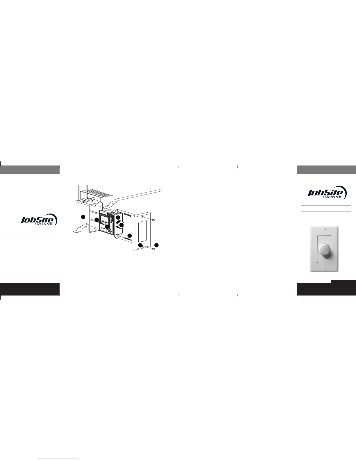
Jobsite V-10-50IM Operation manual

(a) Electrical Box
(b) Speaker Wire
(c) VC-10-50IM Volume Control
(d) Decora-Style Insert (3 supplied)
(e) Knob (3 supplied)
(f) Device Screws (2 supplied)
(g) Decora Wallplate (3 supplied)
(h) Faceplate Screws (6 supplied)
e
f
gh
ab
c
d
10 STEP WALL MOUNT
VOLUME CONTROL
7 98
SPECIFICATIONS
■ Power Handling
50 W (RMS)/100 W (peak music power) per channel
■ Frequency Response
20Hz to 20kHz ± 2dB
■ Minimum Speaker Load
4 ohm
■ Mounting Requirements
In-wall, fits most 18-cubic-inch single-gang
junction boxes at least 2-3/4" D
■ Wiring Requirements
14 to 16 gauge, stranded-copper loudspeaker
wire with two individual runs of two-conductor
wire, or one run of four-conductor wire
■ Colors
Almond, Bone, and White
■ Unit Dimensions
1-5/8" W x 2-5/8" H x 2-9/16" D
■ Faceplate Dimensions
2-3/4" W x 4-1/2" H
LIMITED WARRANTY
JobSite Systems (“JOBSITE”), a Niles Audio Corporation company,
warrants its passive products (those not requiring AC or battery power)
to the original purchaser to be free of manufacturing defects in material
and workmanship for a period of ten years from date of purchase.
JOBSITE warrants its passive loudspeaker products (those not
requiring AC or battery power) to the original purchaser to be free of
manufacturing defects in material and workmanship for a period of five
years from date of purchase.
JOBSITE warrants its indoor/outdoor loudspeaker products to the
original purchaser to be free of manufacturing defects in material
and workmanship for a period of two years from date of purchase.
JOBSITE warrants its all weather rock loudspeaker products to the
original purchaser to be free of manufacturing defects in material and
workmanship for a period of five years from date of purchase.
JOBSITE warrants its active products (those requiring AC or battery
power) to the original purchaser to be free of manufacturing defects in
material and workmanship for a period of two years from date of purchase.
This Warranty is subject to the following additional conditions and
limitations. The Warranty is void and inapplicable if JOBSITE deems
that the product has been used or handled other than in accordance
with the instructions provided by the manufacturer, including, but
not limited to, damage caused by accident, mishandling, improper
installation, abuse, negligence, or normal wear and tear, or any defect
caused by repair to the product other than by JOBSITE or
an authorized JOBSITE wholesale distributor.
To obtain warranty service, you must write to JOBSITE: Include your
name, address, telephone number, model number and serial number
of your unit, and a brief description of the problem. A factory Return
Authorization Number will be sent to you. DO NOT RETURN ANY
UNIT WITHOUT FIRST RECEIVING WRITTEN AUTHORIZATION AND
SHIPPING INSTRUCTIONS FROM JOBSITE.
If the above conditions are met, the purchaser’s sole remedy shall be
to return the product to JOBSITE, in which case JOBSITE will repair
or replace, at its sole option, the defective product without charge for
parts or labor. JOBSITE will return the unit repaired or replaced under
warranty by shipping it by its usual shipping method from the factory
(only) at its expense within the United States of America. THERE ARE
NO OTHER WARRANTIES, INCLUDING, WITHOUT LIMITATION, EITHER
EXPRESS OR IMPLIED WARRANTIES OF MERCHANTABILITY OR
FITNESS FOR A PARTICULAR PURPOSE, WITH RESPECT TO
THE PRODUCT.
REPAIR OR REPLACEMENT AS PROVIDED UNDER THIS WARRANTY
IS THE EXCLUSIVE REMEDY OF THE CONSUMER/PURCHASER.
JOBSITE SHALL NOT BE RESPONSIBLE FOR ANY INCIDENTAL OR
CONSEQUENTIAL DAMAGES EXCEPT TO THE EXTENT PROVIDED (OR
PROHIBITED) BY APPLICABLE LAW.
Some states do not allow the exclusion or limitation of incidental or
consequential damages, so the above limitation may not apply to you.
This warranty gives you specific legal rights, and you may also have
other rights, which vary from state to state.
For the name of the nearest authorized JOBSITE wholesale
distributor, contact:
JobSite Systems
12331 S.W. 130 Street, Miami, Florida 33186
WWW.JOBSITESYSTEMS.COM V-10-50IM
CONTENTS INSTALLATION & USER GUIDE
For Precise Volume
Adjustment In Any Room
JOBSITE SYSTEMS
12331 S.W. 130 STREET, MIAMI, FLORIDA 33186
P 866.4JB.SITE (866.452.7483) – F 305.238.0185
WWW.JOBSITESYSTEMS.COM
©2006 JobSite Systems. All rights reserved. JobSite, Pure
Custom and Niles are registered trademarks of Niles Audio
Corporation and the JobSite Logo is a trademark of Niles Audio
Corporation. All other trademarks are the property of their
respective owners. Some JobSite products (or components
thereof) are manufactured under one or more U.S. Patents,
foreign equivalents and/or pending patents (see product for
details). Because we constantly strive to improve our prod-
ucts, JobSite reserves the right to change product specifica-
tions, descriptions, and prices without notice. The technical
and other specifications of information contained herein are
not intended to set forth all technical and other specifications
of JobSite products. Additional information can be obtained
at WWW.JOBSITESYSTEMS.COM or by calling JobSite at
866.452.7483. DS00507A
DS00507A-0 V-10-50IM.indd 2 10/25/06 10:49:25 AM

5 63 4
Strip 1/4" of insulation from the end of each
wire. Tightly twist the end of each wire until
there are no frayed ends. Insert each wire
into the appropriate hole on the connector
blocks; secure the wiring to the connec-
tors by tightening the small connector
screws. Be certain that proper phasing is
observed—connect the positive terminals
on the V-10-50IM to the positive terminals
on the amplifier and speakers; the negative
terminals on the V-10-50IM to the negative
terminals on the amplifier and speakers.
See Figures 2 and 3.
NOTE: THE INPUTS OF THE V-10-50IM ARE THE
CONNECTOR PINS LABELED “IN”. THE OUTPUTS
ARE THE CONNECTOR PINS LABELED “OUT”. BE
SURE NOT TO REVERSE THESE CONNECTIONS OR
THE V-10-50IM WILL NOT FUNCTION PROPERLY.
4. Set the Impedence Magnification Switch as
determined by the IM charts (Figure 5 and 6).
5. Secure the V-10-50IM to the junction box.
Insert the 1-1/4" long device screws into
the oblong-shaped screw holes on the top
and bottom of the V-10-50IM. Note that the
oblong shape of the screw holes allow you
to position the V-10-50IM so that it is vertical.
Position the V-10-50IM so that the screws
are aligned with the threaded holes in the
junction box. Tighten the screws using a
phillips screwdriver.
INSTALLATION
CONSIDERATIONS
Changing the Color of the Knob
and the Decora Insert
The Decora-style insert and knob on the V-10-
50IM are removable, allowing fast and easy
color changes as needed. Inserts and knobs
are available in a variety of colors. To change
the color of your unit:
1. Obtain the appropriate knob and Decora-
style insert in the desired color from your
Jobsite Systems dealer.
2. Pull the knob off the shaft. See Figure 1.
3. Locate the two plastic mounting tabs at the
top rear of the Decora-style insert. Using
two fingers, simultaneously press both
tabs down (towards the center of the in-
sert) and forward (away from you) until the
insert pops free from its mounting slots.
4. Locate the new Decora-style insert. Hold
the volume control facing you. Insert the
two bottom tabs into the bottom slots first,
then the two tabs on the top (see Figure
1). Press carefully on the front of the insert
to snap it into place.
5. Locate the new knob. Align its flat side to
the flat side of the shaft, and push the knob
onto the shaft. Check the alignment of the
knob by turning it through all positions.
INSTALLATION
If you are installing the V-10-50IM into an exist-
ing wall, take time to consider any possible
obstructions which may be hidden inside the
wall, such as wood and metal studs; electrical,
telephone or other types of wiring; plumbing;
conduit; old wall safes; etc.
1. Install the junction box in the usual manner.
2. Run all the necessary wiring to the V-10-
50IM. Label the wires for future reference.
3. Make the connections to the V-10-50IM.
Locate the connectors for the V-10-50IM.
Figure 1. Changing the V-10-50IM’s knob
and Decora-style insert.
1 2
Figure 3.
Wiring diagram
shows a Jobsite
system with a V-10-
50IM volume control
V-10-50IM
To Speakers
(Output)
Speakers
Receiver
Left
(Input)
Right
(Input)
Figure 2.
Wiring the connectors
OPERATION
1. Make sure the amplifier or receiver power
is OFF and set the volume to minimum.
2. Set the V-10-50IM volume to maximum
(fully clockwise).
3. If you are using a Jobsite speaker selection
system, locate the on/off button which
corresponds to the speaker pair you wish to
play. Set it to the on position.
4. Turn on the amplifier or receiver and select a
source, such as the tuner or CD player.
5. Slowly turn up the amplifier or receiver
volume and set it to a comfortable (not
maximum) listening level. Be careful not
to overdrive or “clip” your amplifier. If the
sound becomes muddy or distorted, you have
reached the limit of your amplifier’s volume
capability and should quickly reduce the
volume to avoid damaging
your speakers.
6. Adjust the volume of the speakers to the
desired listening level using the V-10-50IM.
If all the speaker pairs in your system are
equipped with Jobsite volume controls, you
can leave the amplifier or receiver volume set
at one position and use the Jobsite controls
exclusively.
7. You can turn off the speakers by turning
the knob on the V-10-50IM fully counter-
clockwise, or by pressing the on/off button
on your speaker selector.
Figure 4. Loosening
the screws for a flush fit.
4x
2x
1x 2x
8x
2x
8x
2x
2x
0
1
2
3
4
01 2 3 4 5 6 7 8 9 10 11 12 13 14 15 16
5
6
7
8
4 OHM
Speaker
Pairs
4 OHM
Speaker
Pairs
Figure 6. Amplifier’s minimum speaker load is 8 OHM.
Figure 5. Amplifier’s minimum speaker load is 4 OHM.
4x 8x
4x
4x
2x
1x 2x
8x
2x
2x
0
1
2
3
4
01 2 3 4 5 6 7 8
8 OHM Speakers Pairs
DO NOT OVER-TIGHTEN. In some instances,
you may need to loosen these screws several
turns to allow the V-10-50IM to fit flush with the
Decora cover plate. See Figure 4.
6. Use the shorter plate screws to fasten the
Decora faceplate to the V-10-50IM. DO NOT
OVER-TIGHTEN THE PLATE SCREWS OR YOU
MAY DAMAGE THE FACEPLATE. Line up all the
screws in the same direction for a finished look.
DS00507A-0 V-10-50IM.indd 1 10/25/06 10:49:17 AM
Other Jobsite Controllers manuals

Jobsite
Jobsite V-10-50 Operation manual

Jobsite
Jobsite V-12M User manual

Jobsite
Jobsite V-12/AW User manual

Jobsite
Jobsite V-12/AW User manual

Jobsite
Jobsite V-10-50IM User manual

Jobsite
Jobsite V-12M User manual

Jobsite
Jobsite V-10-50 User manual

Jobsite
Jobsite V-12 User manual

Jobsite
Jobsite V-12M/AWE User manual

Jobsite
Jobsite V-12 User manual