8
SPECIFICATIONS
IR system:
Works with practically all brands of IR remote
controls
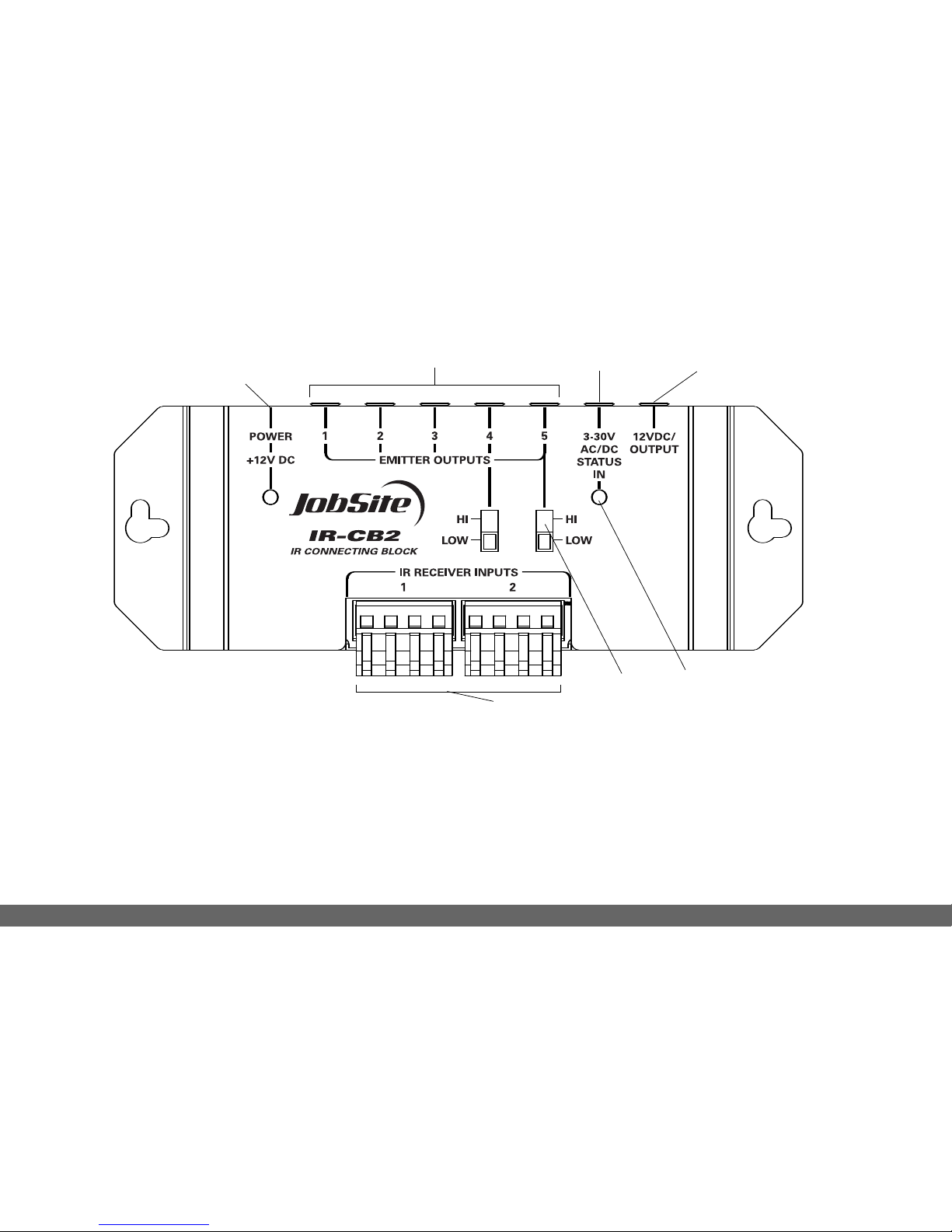
Connections:
2Receiver Inputs, 5 Emitter Outputs, 1 Status Input,
112V DC output
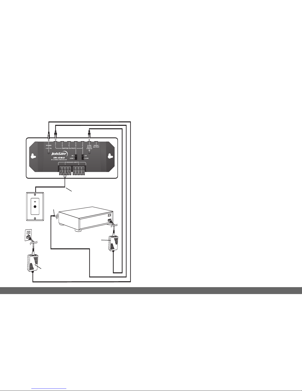
Wiring requirements:
Category 5 or better
Home runs required from each IR receiver
Mounting:
Wall or flat surface: use drywall screws
Dimensions:
5-11/16" wide x 1-1/4" high x 2" deep
Power requirements:
110V to 12V DC power supply (included)
Warranty: 2year limited
LIMITED WARRANTY
JobSite Systems (“JOBSITE”), a Niles Audio Corporation
company, warrants its passive products (those not
requiring AC or battery power) to the original purchaser
to be free of manufacturing defects in material and
workmanship for a period of ten years from date
of purchase.
JOBSITE warrants its passive loudspeaker products
(those not requiring AC or battery power) to the original
purchaser to be free of manufacturing defects in material
and workmanship for a period of five years from date
of purchase.
JOBSITE warrants its indoor/outdoor loudspeaker
products to the original purchaser to be free of
manufacturing defects in material and workmanship for a
period of two years from date of purchase.
JOBSITE warrants its all weather rock loudspeaker
products to the original purchaser to be free of
manufacturing defects in material and workmanship for a
period of five years from date of purchase.
JOBSITE warrants its active products (those requiring AC
or battery power) to the original purchaser to be free of
manufacturing defects in material and workmanship for a
period of two years from date of purchase.