Jobsite M-64 Operation manual

INSTALLATION & USER GUIDE
MULTIZONE RECEIVER
M-64
For Playing Four
Sources in Six
Separate Zones

M-64
MULTIZONE RECEIVER
TABLE OF CONTENTS
FEATURES ......................................................................................................................................................................................................................................................1
PACKAGE CONTENTS...........................................................................................................................................................................................................................1
PRODUCT OVERVIEW............................................................................................................................................................................................................................2
PREPARING FOR INSTALLATION ..................................................................................................................................................................................................3
SYSTEM CONFIGURATIONS .............................................................................................................................................................................................................4
INSTALLATION..........................................................................................................................................................................................................................................15
PROGRAMMING ......................................................................................................................................................................................................................................17
OPERATION.................................................................................................................................................................................................................................................31
TROUBLESHOOTING ............................................................................................................................................................................................................................42
SPECIFICATIONS.....................................................................................................................................................................................................................................43
WARRANTY.................................................................................................................................................................................................................................................44

1
FEATURES
IBuilt-in AM/FM stereo tuner with 20 station presets
I12 independent amplifiers with 30 watts per channel
I4 sources can be selected in any of 6 zones
IOperates with JobSite keypads and remotes
IIncludes handheld remote control
IStable into low impedance loads (4 ohms)
ICSA E65 UL6500 approved
Installation friendly design:
IPower synchronization inputs for external sources and home theater integration
IIndividual preamp outputs for each zone (fixed and variable)
I12V DC control output
IPaging input
IGold plated RCA jacks
PACKAGE CONTENTS
IM-64 x 1
IRemovable AC power cord x 1
IM-64R Remote control x 1
IAA 1.5V Batteries x 2
IFM Dipole antenna x 1
IAM Loop antenna x 1

2
LED Zone ON/OFF Indicator Zone Label Slots Tuner Controls
DB-9 Computer
Interface
Sensor for Capturing IR
Commands
Zone All On/Page
Enable Switches
Programming Controls
and Indicators
Tuner DisplayRemovable Programming CoverMain Power Switch
Sync
Inputs
Keypad Inputs
System
Expansion
Paging Input
Emitter Outputs
IR
Input
12V Control
Output
Tuner Antenna
Inputs
Audio
Inputs
Individual Zone
Preamplifier Output
Removable Speaker
Connector
Removable
Power Cord Socket
Fixed/Variable Preamplifier
Adjustment Switch
Figure 1
PRODUCT OVERVIEW

3
PREPARING FOR INSTALLATION
Source Components
The M-64 has RCA audio inputs for connecting three external source
components. In addition to the built-in AM/FM Tuner, three source
components can be selected by each of the six zones.
A user in one zone can listen to one source component while another user
in a different zone can listen to a different source component (i.e. the CD
can be selected in Zone 1 while the tuner is selected in Zone 2).
Additionally, each of the six zones can be set to an individual volume level.
If more than one zone chooses the same source component, IR control of
that source component is shared between the zones.
Keypads and IR Receivers
Keypads and IR Receivers enable the user to control the JobSite M-64
Multizone Receiver and its connected source components. Source
component IR commands are programmed into the JobSite M-64 Multizone
Receiver. These commands are then triggered when the user presses a
keypad button or issues a JobSite IR command to an IR Receiver.
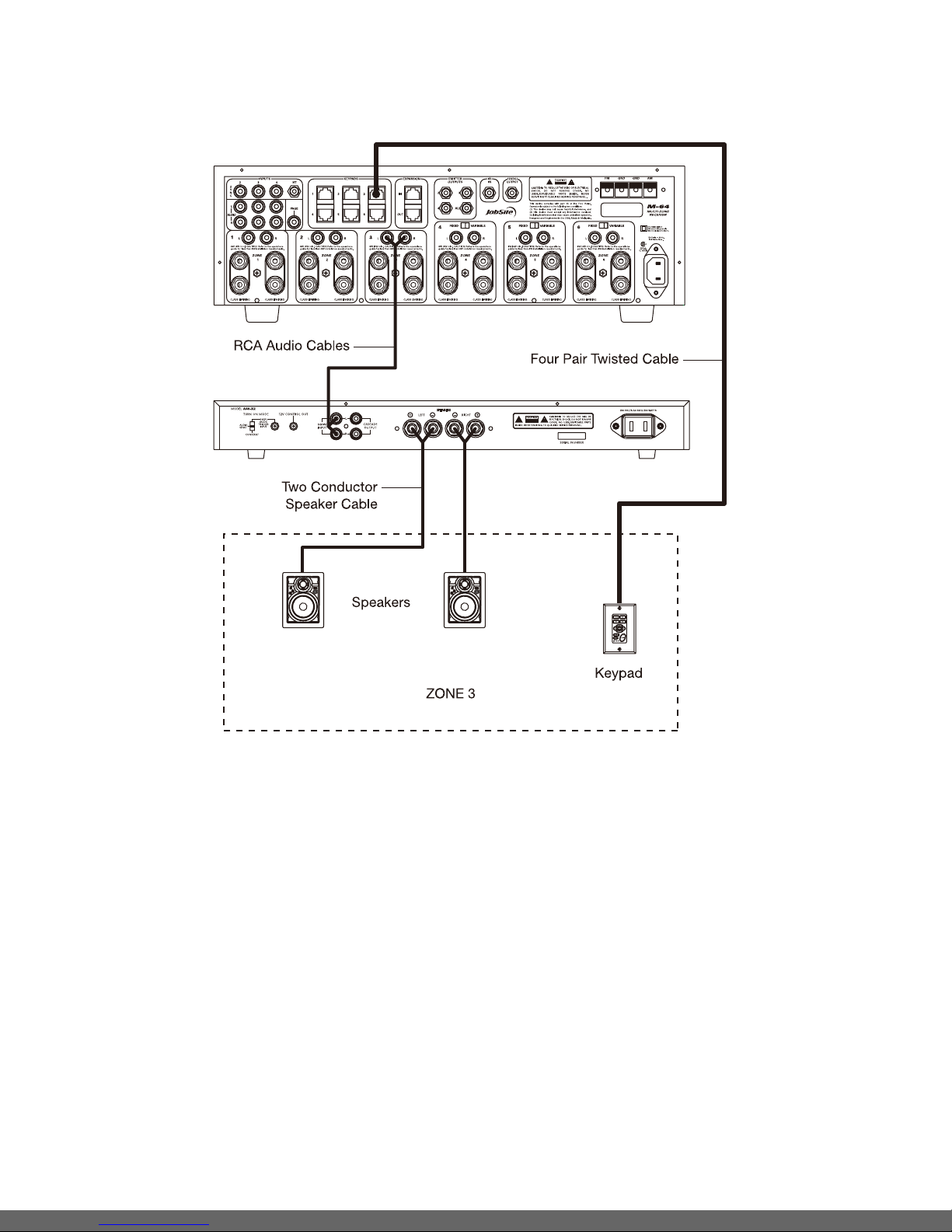
Each zone on the M-64 has a corresponding RJ-45 keypad connector that
is used to connect one M-4KP Master Keypad Module. Each M-4KP 4 Key
Multizone Keypad can be mated with one optional M-10KP 10 Key
Multizone Keypad using an included jumper cable. The M-4KP 4 Key
Multizone Keypad connects to the M-64 with a “home run” of four-pair
twisted cable, terminated with RJ-45 connectors.
A JobSite IR Receiver can be included in any zone and connects directly
to the M-4KP Keypad (see the Installation section of this manual for
more details)
Adding an IR Receiver enables the JobSite M-64R Remote to control the
M-64 and the connected source components. In addition, a source
component’s actual IR commands (i.e., provided by the component’s
original remote control or a learning remote control programmed with these
IR commands) can be used with the IR Receiver to control the source
components.
Important Note: The M-64 does not provide individual operation of identical
source components when using a source component’s factory remote
through an IR Receiver.
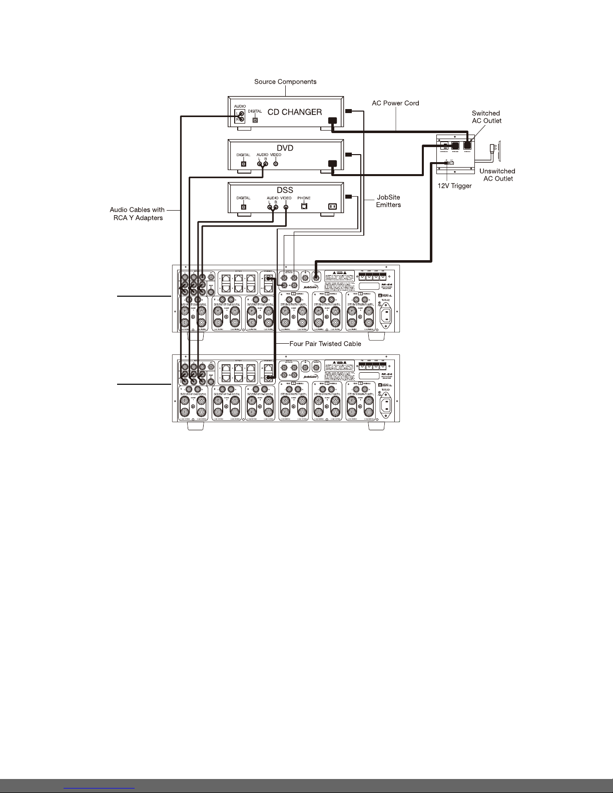
Source-Component Automation
There are two methods of controlling the power ON/OFF of the source
components.
1. Synchronized IR - In Figure 2, the DSS receiver’s power ON/OFF is
synchronized via a video signal connected to the M-64. When the Master
Key/Source Button for the DSS is pressed, the M-64 checks for a video
signal at the Sync Input corresponding to the DSS. The M-64 issues the
power command to turn the DSS ON only when there is no video signal
present and the DSS is OFF.
When the Off Key/Button is pressed in a zone, the M-64 checks to see if
any other zones are on (including the Home Theater Zone sharing sources).
The power command for turning the DSS OFF is issued only if that zone is
the last zone turning OFF in entire system and there is no video signal
present at the Sync Input corresponding to the DSS.
2. Latching Power - In Figure 2, AC power to the DVD and CD changer is
turned on and off via the switched AC outlets of a Voltage-Triggered AC
Power Strip. The 12V Control Output of the M-64 activates the AC Power
Strip, when any one of the six zones is ON (including the Home Theater
Zone sharing sources). The built-in AM/FM tuner is also turned on when
one of the six zones is ON.
Each Master Key on the M-4KP 4 Key Multizone Keypad and its respective
source component are programmable with a sequence of IR commands.
Commands included in the sequence are typically the Play or Channel
commands to start a source playing or to select a particular music or radio
station after the source has been selected.
Note: This sequence will issue each time he source key is pressed.
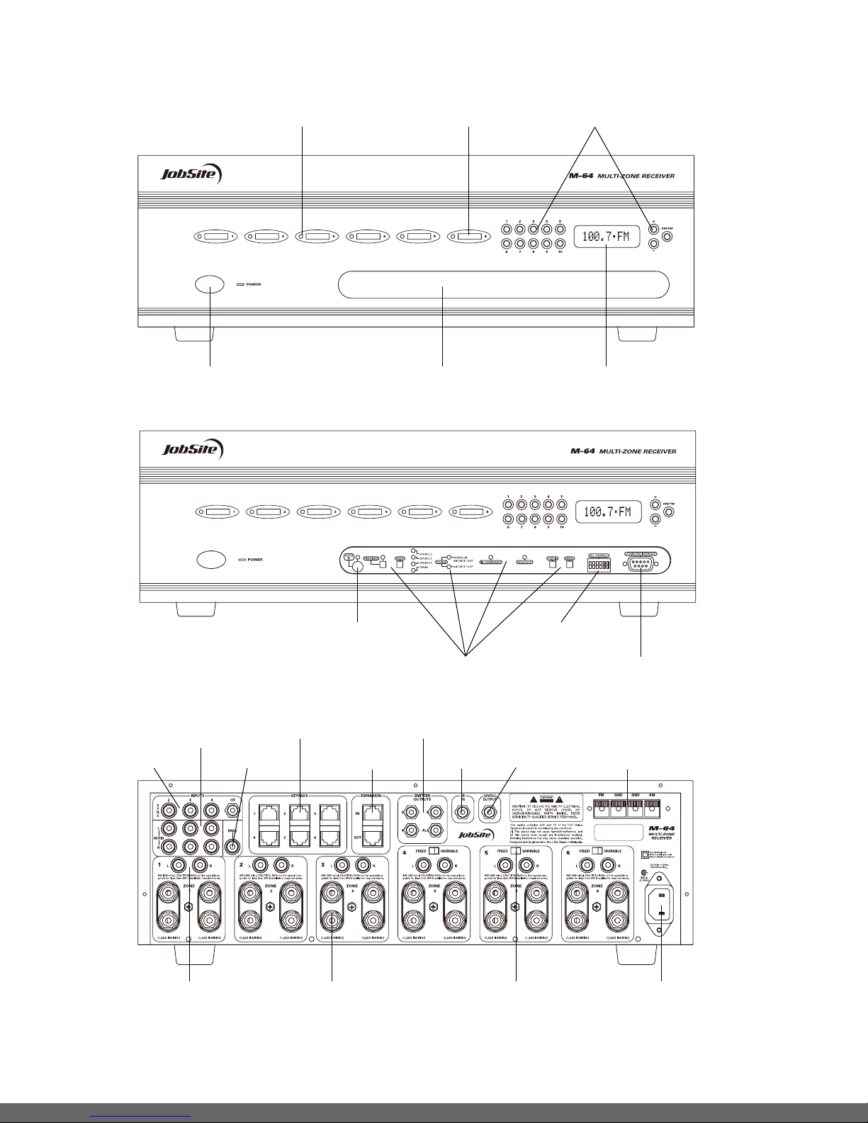
Emitter Outputs
JobSite IR-E1 Emitters™ connect to the numbered emitter outputs on the
rear panel of the JobSite M-64 Multizone Receiver. Emitters send IR
commands to the individual source components for control. An IR-E1HO
Flooding Emitter can be connected to the emitter output labeled ALL to
control more than one source component.
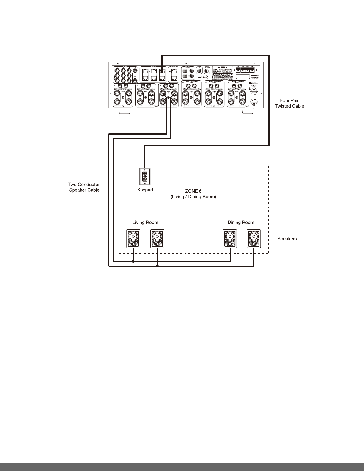
Speakers
Home run speaker cables from the location of the speakers to the M-64.
Connections are made to the M-64’s speaker output terminals speaker
connectors. Mark the cables with Wire labels, describing where the cables
originate from, rather than where they will terminate.

4
Figure 2
CONFIGURATION 1 - BASIC SIX ZONE SYSTEM
This is the simplest of the M-64 configurations (see Figure 2). It depicts one JobSite M-64 Multizone Receiver installed to provide sound to six
listening zones.
Each zone consists of one room with one pair of speakers. One M-4KP 4 Key Multizone Keypad is included in each zone for user control. M-10KP 10 Key
Multizone Keypads and an IR Receiver are added to specific zones as an option.
SYSTEM CONFIGURATIONS

5
Figure 3
CONFIGURATION 2 - Using two pairs of speakers in a single Zone
In Figure 3, speaker cable is connected to the speaker outputs of Zone 3 and then parallel connected to the speakers of the living room and dining room. A
M-4KP Keypad is located in the living room. This configuration is chosen when the speakers in the zone are not required to be played at separate volume
levels or to be turned on and off separately.
A maximum of two pairs of 8 ohm speakers can be added to a zone in this manner. An external amplifier is required for zones with more than two pairs
of speakers.

6
Figure 4
CONFIGURATION 3 - Using an external Amplifier for more power in a single Zone
Each zone of the M-64 provides RCA preamplifier output connections for the connection of external amplifiers. External amplifiers can be used to provide
more power in a zone.
In Figure 4, an external amplifier has been connected to zone 3. Using an amplifier with more than the 30W per channel provides the zone with more
volume for listening in large rooms and outdoors.
Important Note: When using preamplifier outputs for zones 4, 5, and 6, the fixed/variable switch must be in the variable position for this configuration.
Amplifier A45-X2

7
Figure 5
CONFIGURATION 4 - Using an external Amplifier to power multiple rooms of speakers, configured as a single Zone
The preamplifier output connectors on the M-64 for zones 4, 5 and 6 have a fixed/variable setting. Using the fixed setting with an external amplifier enables
a zone to be divided up into individual rooms using conventional JobSite Impedance Matching Volume Controls.
In Figure 5, Zone 6 has been expanded into four rooms. Each room can be On/Off individually and be set at different volume levels.
The speakers for the master bedroom are connected to the M-64’s internal zone amplifier. A M-4KP 4 Key Multizone Keypad is placed in the master
bedroom for control of ON/OFF, source selection, and source operation for the entire zone. However, the volume and mute buttons on the M-4KP 4 Key
Multizone Keypad affect the speakers in the master bedroom only.
JobSite V-12 Impedance-magnifying volume controls enable individual control of the speakers connected to the external zone amplifier in the master
bathroom, the walk-in closet, and the terrace.
Amplifier A45-X2

8
CONFIGURATION 5 - ADDING A SECOND M-64 TO EXPAND TO 12 ZONES
Figure 6
Designated
as the Master
Designated
as Slave #1
More than one M-64 can be used if the system requires more than six zones. A maximum of three M-64s, providing up to 18 zones, can be combined to
create a larger multizone/multi-source system. One M-64 is designated as the Master and the others as Slaves (see Installation Settings on page 19 for
more details).
As shown in Figure 6, a four-pair twisted cable connecting the expansion ports of the two M-64s facilitates communication between them. This
communication enables all zones provided by both M-64s to obtain control of the shared-source components (which are always connected to the Master).
Also, system-wide commands can be issued from any zone (i.e. All Zones ON/OFF).
Sharing Source Components with Two M-64s
The JobSite M-64 Multizone Receivers (Figure 6) share the audio signal from the source components via RCA Y-adapters. Audio signals are connected to
both M-64s.
Source-component control is accomplished via the programming in the master M-64. All Slave M-64s in the system must be left (unprogrammed), except
for tuner-preset stations. All Emitter and Sync Input connections for the shared source components are made to the Master M-64. Keypad/Source Button
commands and zone On/Off status are communicated to the Master M-64 using the System Expansion In/Out connections, providing coordinated control of
all source-components.

9
When sharing source components with three M-64s (see Figure 7) an Audio/Video Distribution Amplifier is required for each source.
Important Note: An Audio/Video Distribution Amplifier is required whenever you are sharing source components with a home theater receiver that shorts
its audio inputs.
CONFIGURATION 6 - ADDING A THIRD M-64 TO EXPAND TO 18 ZONES
Figure 7
Designated
as the Master
Designated
as Slave #1
Designated
as Slave #2

10
An IR-controlled Home Theater surround-sound receiver can be integrated to share source components in a system with the M-64.
Distributing Audio Signals
Audio signals for the shared source components are connected to both the M-64 and the home theater receiver using RCA Y-adapters (Figure <Insert new
Figure 8).
Important Note: If the home theater receiver has shorting audio inputs, an Audio/Video Distribution Amplifier must be used in place of the RCA Y-adapters.
Shared Source Component Control
The Emitter output from the Home Theater IR repeater (Figure 8) is connected to the IR Input of the M-64. The Home Theater IR remote control is now able
to control the shared source components.
A 12V Sync signal is provided from the Home Theater to the Home Theater Sync Input to provide the M-64 with the On/Off status of the Home Theater. This
status enables the M-64 to provide coordinated control of the shared source component's power On/Off.
The Home Theater remote control should be programmed with M-64 source IR commands.
Important Note: When issuing the source component’s actual IR commands from the Home Theater remote control, all IR commands are passed through
to all source-component emitter outputs. Identical brand and model source components cannot be operated individually using these commands.
CONFIGURATION 7 - INTEGRATING AN IR-CONTROLLED HOME THEATER
Figure 8

11
SOURCE POWER SYNCHRONIZATION
What is Source-Power Synchronization?
The M-64 has been designed to keep track of the ON/OFF condition of the
three source components connected to the system. This enables source
components that utilize the same IR command for ON and OFF (Power), to
be automated.
For this feature to function as designed you need “synchronization (sync)”
between the M-64 and source components that utilize the same IR
command for ON and OFF. This assures the users of the system that the
M-64 will always issue Power commands correctly when they press a
Master Key or the Off Key.
Source Power Sync makes it possible for the user to always have a source
component turn ON when they need it on and to always have all the
components turn OFF when they turn the System off.
Source Components that require Power
Synchronization
Source components that utilize the same IR command for ON and OFF
(Power), need to be synchronized. The power button for these source
components sends the same IR command to turn the source components
ON if they are OFF, and to turn them OFF if they are ON. It is necessary to
“synchronize” these source components with the M-64 so it knows not to
send an ON command if the source components are already on (if it did, the
source components would turn off, which is not the desired result).
Conversely, synchronization keeps the M-64 from issuing a “power”
command when the Off Key is pressed, if the source components are
already OFF.
The M-64 has three Sync Inputs for each of the source components. It
allows synchronization via voltage and video signals.
Source Components that do not require
Synchronization
Two types of components do not require synchronization: those
with separate ON and OFF discrete IR commands, and those with
“latching power.”
CONFIGURATION 8 - SYSTEM PAGING WITH AN EXTERNAL TELEPHONE SYSTEM
Figure 9
A Paging Input connection on the rear panel of the M-64 provides a connection for the paging output signal of popular telephone systems for voice paging
through the speakers in the listening zones. Paging volume level can be adjusted by the M-64 (see Installation Settings on page 28 for more information).
An Audio/Video Distribution Amplifier is required when connecting a telephone system to more than one M-64 in larger systems.

Choosing a Synchronization Method
Once you establish that all source components in the system have compatible IR commands, the next step is to choose the appropriate Sync Method for
each component.
There are two ways to detect when a component is ON or OFF: Video or Voltage Sync.
Video Sync
Video Sync is the easiest and most reliable method of synchronization. Most video sources have a video output active only when the device is
ON. This type of video output provides an excellent method for component synchronization.
The M-64 has three source-synchronization connections that can accept either 12V or video input. In Figure 10, the video output of a DSS is connected
to both a TV and the corresponding Sync Input for the DSS using an RCA Y-adapter. Picture quality will be unaffected due to the high impedance of the
Sync Input.
If the source component has two video outputs, the need for an RCA Y-adapter is eliminated. Simply connect the first video output to its normal system
destination, and the second video output will be dedicated for the Sync Input.
12
Source Components with separate ON/OFF discrete
IR commands
There are source components that are included with and respond to
separate ON and OFF IR commands. Synchronization is not required for
them. When power commands are programmed as separate ON and OFF,
the M-64 will issue ON commands only if Sync is not present. Separate OFF
commands for source components are always issued when the last zone
turns OFF regardless of sync status.
Source Components with “Latching Power”
Some source components, like CD players and tape decks, are usually
plugged into the switched AC outlet of the preamplifier/receiver that they
are installed with. These components simply turn ON when the system’s
receiver/preamplifier turns on, meaning that they “latch” into an ON or OFF
state and do not need an IR command to turn ON or OFF.
Because they turn ON as soon as there is power on their AC cord, once the
preamplifier/receiver is turned on, these components will be turned on as
well. They do not need individual synchronization.
Since the M-64 does not provide a switched AC outlet, the 12V Control
Output connected to a Voltage Triggered AC Power Strip provides perfect
control of latching source components (see Configuration 1 in the Systems
Configurations section of this manual for more information).
Figure 10

13
Voltage Sync
Voltage Sync is also a reliable method of synchronization if chosen and
implemented correctly. The Sync Inputs can detect the control out voltage
from a Signal Sensing product interfaced to the source component.
Current Sensing synchronizes a component by detecting the changes in the
AC power draw that occurs with a component when it turns ON and OFF. In
Figure 11, a Current Sensing Switch senses the change in power
consumption of a CD changer when it is turned ON. When it senses that
change, it outputs a 12V DC signal. The synchronized CD changer’s AC
power plug is connected to the current sensing outlet on the current
sensing device. The devices 12Volt DC output is connected to the M-64’s
Sync Input dedicated to the CD changer using a cable with bare wire to
mini-plug.
Placement
Place the M-64 on a flat, level surface such as a table or shelf, with its
weight equally distributed on each of its four feet. Placing the weight of the
amplifier on the rear or front panel for even an instant will result in damage
to the amplifier's connectors and controls.
Like any high-fidelity component, the M-64 will last much longer if it is given
adequate ventilation for proper cooling. When installing the M-64 in a
cabinet, be sure that the cabinet’s rear is open to receive fresh air in order
to provide proper cooling (see Figure 12). If the cabinet’s design does not
accommodate an open rear, install two small “boxer fans” to provide
continuous airflow into and out of the cabinet (see Figure 13). Place the
M-64 so it has at least seven inches of free air space above it. If the
amplifier is located on a carpeted surface, place a board under the
amplifier’s feet. Do not block the ventilation holes on the top and bottom
of the M-64.
Documenting your System and labeling wires
Because the M-64 offers so many configuration possibilities it is important
to plan carefully before you install it. Draw a block diagram of your system
to record how you plan to connect your M-64. Mark all cables with Wire
labels, describing where the cables originate from, rather than where they
will terminate. When you get to the Programming section of this manual, fill
out the System Programming Worksheet and the Source Component
Worksheets. Documenting the system leaves you and your customer, with
a permanent record of the important system design and programming
information.
Tools Required:
I1/8" Slotted screwdriver
IWire stripper
ICAT 5 Crimper tool
IRJ 45 Connectors
IWire labels
Figure 11
Make sure that there is a minimum of 7” of
free air space above the amplifier and 3”
on each side for proper ventilation.
Allow a minimum of 2” of depth behind unit to
accommodate cables and connectors.
Figure 12
Figure 13
If the cabinet rear is not open to fresh air or if you’re using low-
impedance loads, install two “boxer fans” to provide continuous air
flow into and out of the cabinet.
Boxer Fan (55 CFM) directly
centered 2” behind the M-64.
Boxer Fan (55 CFM) directly
centered 7” on top of the M-64.
CAUTION! When using low-
impedance speaker loads (less
than 8 ohms Nominal) refer to
Figure 13 for proper placement.

14
Terminating Four-Pair Twisted Cable
The M-4KP Master Keypad Modules, the Expander, and the M-64’s
System Expansion connections require a four-pair twisted cable with a
one-to-one wiring configuration. To maintain consistency throughout all
JobSite installations, we recommend the color-coding pattern described
in Figure 14. However, you may follow the color-coding pattern of your
choice, as long as it is used consistently throughout the system.
Figure 15
Figure 16
1= Green/White
2= Green
3= Orange/White
4= Blue
5= Blue/White
6= Orange
7= Brown/White
8= Brown
Figure 14
Connecting the M-4KP 4 Key
Multizone Keypads to the Home
Run of Four-pair Twisted Cable
The home run of four-pair twisted cable is
terminated with a male RJ-45 connector and
plugged into the rear panel jack labeled
SYSTEM on the M-4KP 4 Key Multizone
Keypad (see Figure 15).
Connecting M-10KP Keypads
Each M-4KP 4 Key Multizone Keypad can be mated with one optional M-10KP 10
Key Multizone Keypad using an included jumper cable (see Figure 16).
Connecting IR Receivers
Figure 17

15
Source-Component Power and Home Theater
Synchronization Signals
1. Video Synchronization from a Source Component to a M-64 Sync Input
An RCA Y-adapter is used to split the video output of a source
component for connection to one of the three Source Sync Inputs of the
M-64 (2, 3, or 4). One side of the RCA Y-adapter connects to the
appropriate Source Sync Input and the other side connects to the
intended destination for the video signal (i.e., the video input of a TV,
receiver or RF modulator).
The need for a RCA Y-adapter can be avoided if your video source has
two video outputs. One video output connects to a Source Sync Input
and the other to the intended destination of the video signal.
Important Note: Source Sync Inputs are designed with high-input
impedances so as not to affect the quality of the video signal when using
an RCA Y-adapter.
2. Voltage Sync from a Source Component to a M-64 Sync Input
When obtaining a 12V sync signal from a source component (refer to the
Source Power Synchronization section of this manual for more
information), an Accessory Cable connected to a Radio Shack 274-326
mini-plug to male RCA adapter provides proper connection to any of the
three Source Sync Inputs.
3. 12V Home Theater Sync to Home Theater Sync Input
The 12V Home Theater sync signal connects with a mini-plug to the
Home Theater Sync Input.
Keypad Inputs
4. Keypads to Keypad Inputs for Zones 1-6
Four-pair twisted cable, terminated with male RJ-45 plugs, connects the
keypads to the zoned Keypad Inputs (for more information on
Terminating Four-Pair Twisted Cable, refer to page 14).
Figure 18
INSTALLATION
Connection Overview

16
System Expansion
5. System Expansion Input to System Expansion Output
Four-pair twisted cable, terminated with male RJ-45 plugs, connects
multiple M-64's using the System Expansion Input and Output terminals.
Connections are made from the Output of one of the M-64's Slave, to the
Input of the Master M-64. (For more information on Terminating four-pair
twisted cable, refer to page 14).
IR Emitters
6. Low-Output Emitter to the Emitter Outputs
The mini-plug end of a JobSite Low Output Emitter, Model IR-E1
connects into the Emitter Outputs 2-4. The Micro-Emitter portion of the
IR-E1 is placed directly over the IR Receiver of the corresponding source
component (Source 2 for Emitter 2, Source 3 for Emitter, Source 4 for
Emitter 4) and adheres with the included peel-back tape.
7. High-Output Emitter to the Emitter Outputs
The mini-plug end of a JobSite High Output Emitter, Model IR-E1HO
connects to the Emitter Output labeled ALL. The IR-E1HO is strategically
positioned to provide IR transmission to all source components
and adheres with its included Velcro mounting system. High-Output
Emitters cannot be used if you are using two of the same components
in a system design.
Home Theater Control System
8. IR Output of a Home Theater Control System to the IR Input
The mini-plug end of an Accessory Cable connects a Home Theater
Control System to the IR Input.
12V Control Signals
9. 12V Control Output to a Voltage Triggered Device
The mini-plug end of an Accessory Cable connects the 12V Control
Output to the Trigger Input of a voltage-activated device. The12V output
is active when any zone is turned on.
AM/FM Antennas
10. FM Dipole Antenna
The included FM Dipole Antenna connects with its bare-wire ends to
the spring-loaded terminals labeled FM and GND. The antenna is then
positioned and mounted for proper reception.
11. AM Loop Antenna
The included AM Loop Antenna connects with its bare-wire ends to the
spring-loaded terminals labeled AM and GND. The antenna is then
positioned and mounted for proper reception.
Source-Component Audio Signals
12. Audio Output of Source Components to the M-64
Male-to-male RCA Audio Cables connect the three external audio
sources.
Telephone Paging
13. Paging Output of Telephone System to M-64 Page Input
A male-to-male RCA Audio Cable connects the paging output of a
telephone system to the M-64.
Preamplifier Zone Outputs
14. Zones 1-6 (4-6 set to Variable Mode)
Male-to-male RCA Audio Cables connect Zone Outputs 1-6 to an
external amplifier for more power in a zone (refer to System
Configurations for more details).
15. Zones 4-6 Set to Fixed Mode
Male-to-male RCA Audio Cables connect Zone Outputs 4-6 (set to fixed
output mode) to an external amplifier for more rooms in a zone (refer to
System Configuration for more details).
Speakers
16. Zones 1-6
Speaker wire connectors connect speaker wires from the speakers
placed in the listening zones.
AC Power
17. Removable AC Power Cord
The removable AC power cord (included with the M-64) connects to the
removable power-cord socket and to an AC power outlet.
Main Power Switch
18. Turn the main power to the receiver ON and OFF. Note: equipmennt is
not completely disconnected from the main power source when power
switch is in the OFF position.
18. Main Power Switch

3UNIT MODE AND ZONE LABELS (CHOOSE ONLY ONE: A, B OR C)
1 62345
❏(A) MASTER
712891011
❏(B) SLAVE 1
13 1814 15 16 17
❏(C) SLAVE 2
1JOB TITLE
4TUNER PRESETS
AM
1 _______________
2 _______________
3_______________
4 _______________
5_______________
6_______________
7_______________
8 _______________
9_______________
10 _______________
FM
1 _______________
2 _______________
3_______________
4 _______________
5_______________
6_______________
7_______________
8 _______________
9_______________
10 _______________
5TUNER SE UENCE
STEP TUNER COMMAND STEP TUNER COMMAND
1
2
3
4
5
6
7
8
9
10
2SYSTEMDESIGNER
Document the customer’s name. Document the system designer’s name.
Document the Master, Slave 1, or Slave 2 setting. Document the Labels used for the Zone Label slots.
Document the AM and FM Presets stored in the Tuner Memory.
Document the Tuner Sequence.
Mr. Smith Joe Installer
Kitchen
Patio Jacuzzi Exercise Bedroom Terrace
620
830
910
1010
1050
93.9
94.9
96.5
100.7
102.3
1070
1090
1110
1140
1160
103.5
104.7
105.1
106.5
107.9
FM
Figure 19
Fav
1
6ALL ON /PAGE
ZONE ALL ON / PAGE
1
2
3
4
5
❏
6
❏
❏
❏
❏
❏
There are DIP switches on
the front panel to deter-
mine which zones will be
enabled to the ALL-ON and
PAGE features.
7VOLUME SETTINGS
ON VOLUME ________
MAX VOLUME ________
PAGE VOLUME ________
Note: Volume Settings affect
all Zones.
Document the numeric value for
each volume setting.
8PREAMP OUTPUTS
*Zones 1-3 are variable only.
AMP FIXED/ VARIABLE
1 _________________
❏❏
/
❏❏
/
❏❏
/
2 _________________
3 _________________
4 _________________
5 _________________
6 _________________
*
*
*
Document the amplifier to which the preamp
outputs are connected, and the mode selected
(i.e., fixed or variable for zones 4, 5, and 6).
Check the ones that have been enabled to the ALL-
ON/PAGE feature.
PROGRAMING
Documenting the System Configuration
Programming Documentation
Documenting the M-64’s programming is critical to execute the programming procedure. Program documentation enables you to accomplish programming
quickly and accurately, and provides a record of the configuration for future reference. Programming Worksheets are provided in this manual to document
all system configuration programming, including IR commands and sequences. Remove them and fill them out using the examples given. Use a pencil
when documenting. If you need additional sheets, make photocopies.
M-64 System Programming Worksheet
17

18
1JOB TITLE 2SYSTEMDESIGNER
3CHOOSE MASTER KEY
MASTER KEY NUMBER (2, 3, 4): ___________ MASTER KEY LABEL: ____________________
4PROGRAM SOURCE COMPONENT POWER
BRAND: __________________________________ MODEL: __________________________________
COMPONENT
COMPONENT SYNC
❏Yes ❏No If Yes, SYNC TYPE:
❏Video ❏12V
POWER PROGRAMMING
❏Single “Power” IR Command
❏Two Separate ON and OFF IR Commands
❏Latching Power
Document the customer’s name. Document the system designer’s name.
Document the number of the Master Key Document the label used for the Master Key (i.e., source
component, music category, or DSS/Radio Station, etc.)
Mr. Smith Joe Installer
2
DVD
Denon
DVD-2800
Document the brand and model number of the source component that is associated with the Master Key
Document if the source-component is connected
to a sync input. If yes, document the sync type
Document the type of activation
the source component requires
Figure 20
5PROGRAM FUNCTION KEY IR COMMANDS
FUNCTION KEY/BUTTON SOURCE IR COMMAND
Play
Stop
Pause
Rewind <<
FF>>
*
Arrow Up
Arrow Down
Arrow Right
Arrow Left
M
G
E
P
Surf +
Surf –
AM
FUNCTION KEY/BUTTON SOURCE IR COMMAND
FM
1
2
3
4
5
6
7
8
9
0
–
+
Random
Group
Disc
Fav
6PROGRAM SEQUENCE
STEP
FUNCTION KEY/BUTTON
or DELAY TIME
SOURCE IR COMMAND
or
DELAY
1
2
3
4
5
STEP
FUNCTION KEY/BUTTON
or DELAY TIME
SOURCE IR COMMAND
or
DELAY
6
7
8
9
10
Document the IR commands in their function key/button locations
Play
Stop
Pause
Rewind
Fast Forward
Pause
Next Chapter
Last Chapter
Next Chapter
Last Chapter
1
2
3
4
5
6
7
8
9
0
Random
Play Play
Document the IR Commands and Delays included in the Sequence
Figure 22
Figure 21
Function Keys/Buttons Programming
Figure 21 depicts the section of the Source Component Programming Worksheet that corresponds to the source component function key/button
programming. Each programmed source component has one worksheet filled out specifying what particular IR commands have been programmed and to
which function key/button they have been assigned.
Sequence Programming
Figure 22 depicts the section of the Source Component Programming Worksheet that corresponds to the Sequence programming. Each
programmed source component has one worksheet filled out specifying what particular IR commands and delays have been programmed to the Master
Keys Sequence.
M-64 Source Component Programming Worksheet
Other manuals for M-64
1
Table of contents
Other Jobsite Receiver manuals

Jobsite
Jobsite IR-CB1 Operation manual

Jobsite
Jobsite M-64 User manual

Jobsite
Jobsite IR-FMR MKII User manual

Jobsite
Jobsite IR-CB2 Operation manual

Jobsite
Jobsite IR-CB4 User manual

Jobsite
Jobsite IR-SMR User manual

Jobsite
Jobsite IR-WMR User manual

Jobsite
Jobsite IR-CB1 User manual

Jobsite
Jobsite IR-CB2 User manual

Jobsite
Jobsite IR-FMR User manual
Popular Receiver manuals by other brands

Sony
Sony STR-DG800 operating instructions

ViseeO
ViseeO CARK 11 user manual

ASC
ASC ASC300LW instruction manual

SHENZHEN FLYING INDUSTRY DEVELOPMENT CO.,LTD
SHENZHEN FLYING INDUSTRY DEVELOPMENT CO.,LTD S1UA-DC06-ANT3 user manual

Meyin
Meyin RC-821 user manual

Pioneer
Pioneer SC-07 - Elite AV Network Receiver Service manual