manuals.online logo
Brands
  1. Home
  2. •
  3. Brands
  4. •
  5. Jobsite
  6. •
  7. Touch Terminal
  8. •
  9. Jobsite V-T4M User manual

Jobsite V-T4M User manual

Other manuals for V-T4M

1

Other Jobsite Touch Terminal manuals

Jobsite V-T8 User manual

Jobsite

Jobsite V-T8 User manual

Jobsite V-T4M User manual

Jobsite

Jobsite V-T4M User manual

Jobsite V-T8 User manual

Jobsite

Jobsite V-T8 User manual

Popular Touch Terminal manuals by other brands

Omron NT11S Operation manual

Omron

Omron NT11S Operation manual

Partner SP-820 user manual

Partner

Partner SP-820 user manual

BBPOS WisePad 2 instruction manual

BBPOS

BBPOS WisePad 2 instruction manual

Anywire ASLINKAMP L-A1AW Series Product guide

Anywire

Anywire ASLINKAMP L-A1AW Series Product guide

Festo VIFB4 Series Brief description

Festo

Festo VIFB4 Series Brief description

Linksz CMDA FWT-8828 user manual

Linksz

Linksz CMDA FWT-8828 user manual

Heisei Electronics Q-POS 815 user guide

Heisei Electronics

Heisei Electronics Q-POS 815 user guide

ANUBIS POS50 Series quick guide

ANUBIS

ANUBIS POS50 Series quick guide

Amano MTX-15 installation guide

Amano

Amano MTX-15 installation guide

FLOWBIRD CWT Compact Touch manual

FLOWBIRD

FLOWBIRD CWT Compact Touch manual

Demco SP7 installation guide

Demco

Demco SP7 installation guide

Lathem PC600 Series user guide

Lathem

Lathem PC600 Series user guide

Partner MF-2352 user manual

Partner

Partner MF-2352 user manual

NCR RealPOS 7460-2 supplementary guide

NCR

NCR RealPOS 7460-2 supplementary guide

Simrad MS50 Manual guide

Simrad

Simrad MS50 Manual guide

Unitech MR350 MKII Software guide

Unitech

Unitech MR350 MKII Software guide

Jungheinrich WMT 210 Service manual

Jungheinrich

Jungheinrich WMT 210 Service manual

Motorola MTP850 user guide

Motorola

Motorola MTP850 user guide

manuals.online logo
manuals.online logoBrands
  • About & Mission
  • Contact us
  • Privacy Policy
  • Terms and Conditions

Copyright 2025 Manuals.Online. All Rights Reserved.

For Parallel Signal Distribution to
Multiple Muting Volume Controls
MUTING VOLUME CONTROL CONNECTION TERMINAL
V-T4M
DATA SHEET
V-T4M
MUTING VOLUME CONTROL CONNECTION TERMINAL
FEATURES
• Safely connect up to four speaker pairs to a single amplifier or receiver
• High power handling capability
• Built-in protection circuit
•Compatible with all 4 ohm capable amplifiers or receivers
• Non skid feet for unit stability
• Includes customized
room labels
INSTALLATION FRIENDLY DESIGN:
• Accepts up to 14 gauge wire
• Snap and lock connector secures wire in place without the use of
a screwdriver
SPECIFICATIONS
•Mounting: In a structured wiring Cabinet using Christmas tree snap-in
plugs (included)
• Wall or Flat Surface: Use drywall screws
• Power handling: 100 watts per channel
• Frequency response: +0 dB, -0 dB (flat) from 20Hz to 20kHz
WIRING REQUIREMENTS
• 2 individual runs of 2-conductor 14-18 gauge speaker wire or 1 run of
4 conductor
• 110V to 12V DC power supply at 200 ma (included)
MOUNTING:
•Table-top
DIMENSIONS:
• 6-7/8" wide x 3" high x 1-1/4" deep
WARRANTY:
•2 year limited
MUTING VOLUME CONTROL CONNECTION TERMINAL
V-T4M
JOBSITE SYSTEMS
12331 SW 130 STREET
MIAMI, FL 33186
P866.4JB.SITE (866.452.7483)
F305.238.0185
WWW.JOBSITESYSTEMS.COM
MUTING VOLUME CONTROL CONNECTION TERMINAL
V-T4M
PREPARING FOR INSTALLATION:
The Speakers/Volume Control cables, Amplifier cables and 12V DC power
supply cable must all reach the proposed location of the V-T4M distribution hub.
Mark the cables with Wire labels, describing where the cables originate from,
rather than where they will terminate. Locate a switched AC outlet on your
Receiver or Amplifier to be used to power the V-T4M power supply.
INSTALLATION:
1. Select an appropriate location for the V-T4M
2. Run all the necessary wiring to the V-T4M. Label the wires for
future reference.
3. Strip 1/4" of insulation from the end of each wire. Tightly twist the end of
each wire until no frayed ends remain.
4. Locate the snap and lock connectors and remove them if they are plugged
in. The four-position connector plugs are for speaker wires; the two-position
connector plugs are for 12V wires.
5. Use a small flathead screwdriver or your thumb to raise the locking tabs,
exposing the holes on the connectors.
6. Insert each wire into the appropriate hole and snap down the locking tabs.
7. Insert the smooth side of the connector plug into the smooth side of the V-
T4M socket.
8. Connect the Amplifier to the connector terminal labeled: INPUT
FROM AMP.
9. Connect the Speaker wires to the connector terminals labeled: OUTPUTS
TO VOLUME CONTROLS.
10. Connect the 12V wires to the connector terminals labeled: OUTPUTS TO
MUTING RELAYS.
11. Plug the 12V DC power supply connector into the V-T4M socket
marked POWER.
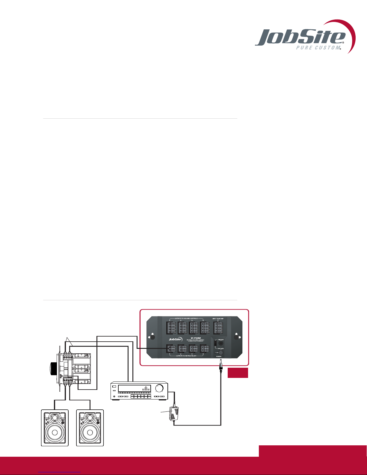
V-T4M INSTALLATION DIAGRAM
V-T4M
Stereo Receiver
12V DC Power Supply
(Not Supplied) plugged into
the Switched Outlet
Speakers
Input From
Amplifier
Output to
Speakers
V-12M
JOBSITE SYSTEMS
12331 SW 130 STREET
MIAMI, FL 33186
P866.4JB.SITE (866.452.7483)
F305.238.0185
WWW.JOBSITESYSTEMS.COM
©2004 Niles Audio Corporation. JobSite,
Pure Custom and Niles are registered
trademarks of Niles Audio Corporation
and the JobSite Logo is a trademark of
Niles Audio Corporation. JSVT4MPDF
Specifications subject to change without notice.