manuals.online logo
Brands
  1. Home
  2. •
  3. Brands
  4. •
  5. Joerns
  6. •
  7. Medical Equipment
  8. •
  9. Joerns Hoyer User manual

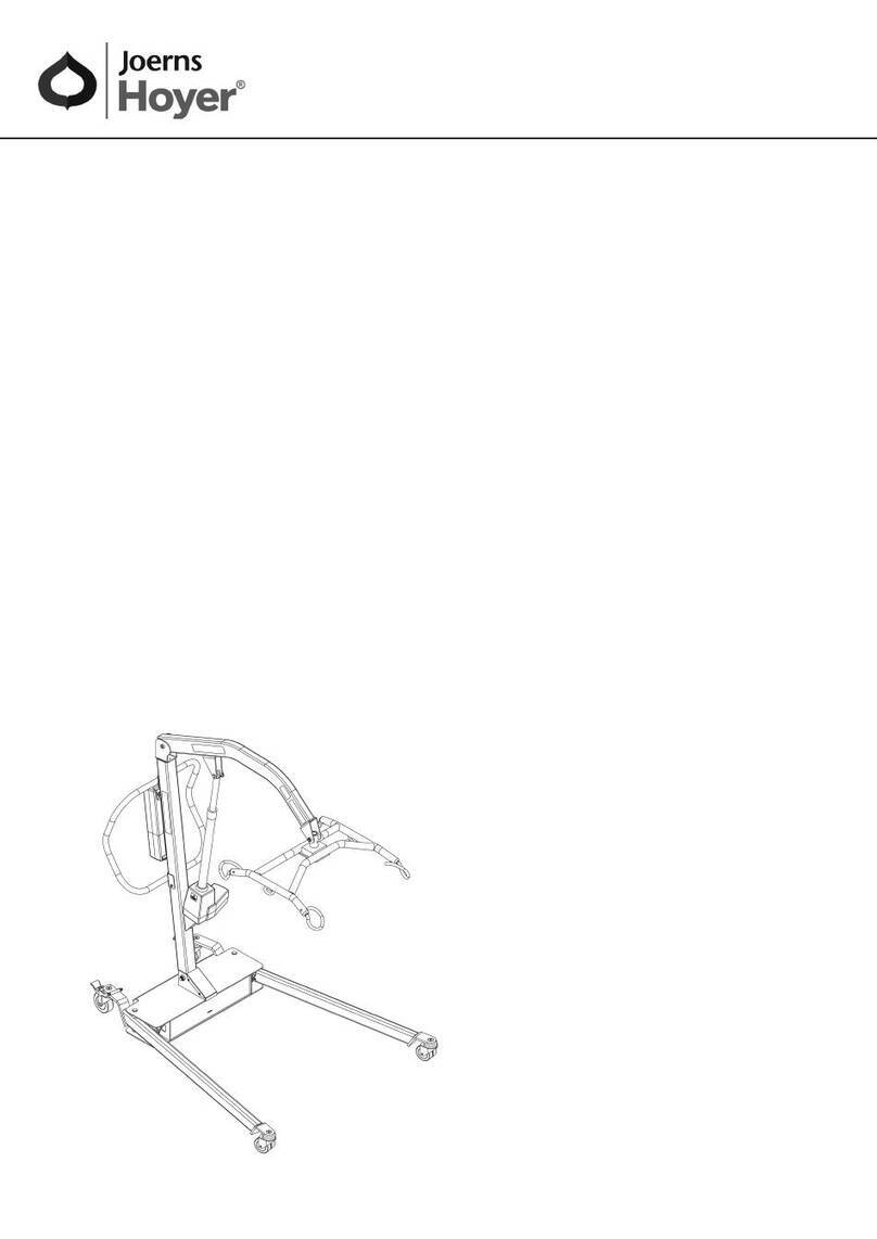
Joerns Hoyer User manual

Service Manual
Hoyer®Switch
2
Hoyer®
Switch
Contents
Inspection Criteria...................................................................................................................................... 3
Service / Repair Schedule......................................................................................................................... 4
Torque Settings.......................................................................................................................................... 8
Notes ....................................................................................................................................................... 10
Hoyer®
Switch
3
Joerns Healthcare Ltd recommends the Hoyer Switch and its accessories are subjected to inspection and
maintenance, as detailed in this manual, at appropriate intervals depending on a risk assessment of the
frequency of use and environmental factors. This will ensure the equipment is adequately maintained and
remains safe for use as detailed in PUWER (Provision and Use of Work Equipment Regulations). The risk
assessment is necessary as PUWER does not detail specic time intervals.
CAUTION
In the event of identifying any faulty items, please contact your local authorized service provider
or Joerns Healthcare directly.
Frame
• Check the operation of the sliding section quick release pins.
• Make sure the frame is fully engaged into the base supports.
• Ensure both frame locking knobs are fully tightened.
Casters and Wheels
• Check all casters and wheels for rm attachment to the base.
• Check for free rotation of the wheels and the casters swivel.
• Check for excessive wear, cracking or splits on the center wheel outer tread and the corner caster
wheels.
• Where possible, remove any build up of threads, hair or bers.
• Lubricate the swivel and axle bearings, if necessary, with a light mineral based grease or food grade
spray lubricant.
• Check correct operation of the brakes.
Cleaning
Clean with ordinary soap and water and/or any hard surface disinfectant. Harsh chemical cleaners or
abrasives should be avoided as these may damage the surface nish of the product. After cleaning, the
unit should be thoroughly dried.
WARNING
HOYER RECOMMENDS THE USE OF GENUINE HOYER PARTS. Hoyer sling/belt and products are
designed to be compatible with one another. For country specific guidance on sling/belt use and
compatibility, please refer to the sling/belt label or contact your local market distributor or Joerns
Healthcare.
Inspection Criteria
4
Hoyer®
Switch
Tools Required
• 5mm hex key
• 6mm hex key
• 8mm A/F combination wrench
• 2 x 10mm A/F combination wrench
• 14mm A/F combination wrench
• 16mm A/F combination wrench
• 0-50Nm range torque wrench
• 17mm A/F socket
• Socket wrench
• Medium weight hammer
• Large (7mm) at blade screwdriver
Corner Casters
NOTE: To aid removal, it is recommended the frame is removed as detailed in the ‘Frame Removal’
procedure.
Removal
1. Unscrew the caster spindle using 2-o󰀨 10mm A/F combination wrenches.
2. Withdraw the spindle from the caster wheel.
3. Remove the caster wheel from the caster swivel bracket.
4. Unscrew the caster swivel bracket retaining nut using a 17mm A/F socket and socket wrench.
5. Withdraw the caster swivel bracket from the M10 retaining stud.
6. Tap out the M10 retaining stud from the base using a medium weight hammer.
Replacement
1. Insert the M10 retaining stud through the square hole in the base.
NOTE: Ensure the square shank of the retaining stud locates correctly in the square hole in the base.
2. Tap the M10 retaining stud into the base using a medium weight hammer.
3. Unscrew the caster spindle of the replacement corner caster using 2-o󰀨 10mm A/F combination
wrenches.
4. Withdraw the spindle from the caster wheel.
5. Remove the caster wheel from the caster swivel bracket.
6. Correctly locate the caster swivel bracket over the M10 retaining stud.
7. Screw the M10 retaining nut onto the M10 retaining stud and tighten to 25Nm using a 17mm A/F
socket and socket wrench.
8. Correctly position the caster wheel between the caster swivel bracket and insert the caster spindle
through the swivel bracket and caster wheel.
9. Screw the M6 nut onto the caster spindle and tighten to 15Nm using 2-o󰀨 10mm A/F combination
wrenches.
10. Replace the frame as detailed in the ’Frame Replacement’ procedure.
Service / Repair Schedule
Hoyer®
Switch
5
Center Wheels
NOTE: The frame must be removed to enable removal of the center wheels as detailed in the ‘Frame
Removal’ procedure.
Removal
1. Unscrew the center wheel bolt using a 6mm hex key and a 16mm A/F combination wrench.
2. Withdraw the center wheel bolt from the wheel.
3. The wheel will now be free.
Replacement
1. Insert the sleeve through the center hole of the wheel.
2. Insert the button head wheel bolt through the sleeve and wheel.
3. Insert the button head wheel bolt and sleeve through the holes in the center wheel bracket (front and
rear) on the base.
4. Screw the M10 domed nut onto the wheel bolt and tighten to 25Nm using a 16mm A/F combination
wrench and a 6mm hex key.
5. Replace the frame as detailed in the ‘Frame Replacement’ procedure.
Frame
Removal
1. Unscrew both frame securing knobs by rotating counter-clockwise until they disengage from the
threaded retaining supports on the base.
2. Withdraw the securing knobs from the frame.
3. Withdraw the frame from the retaining supports on the base.
Replacement
1. Insert the frame into the retaining supports on the base.
NOTE: Ensure the slots in the bottom of the frame tubes correctly locate over the center wheel
sleeves. Ensure correct orientation of the frame i.e. knee pads facing away from the operator.
2. Insert the frame securing knobs through the holes in the frame.
NOTE: Ensure the plastic frame clamps are correctly orientated on the frame securing knobs prior to
inserting through the frame.
3. Screw the frame securing knobs into the supports on the base and hand tighten securely.
6
Hoyer®
Switch
Brake Pedal/Pad
Removal
1. Unscrew the right hand brake lever M8 domed securing nut using a 14mm A/F combination wrench.
2. Withdraw the brake lever, brake lever securing bolt, nylon bush and brake pad spring from the hole in
the base.
3. Remove the retaining circlip from the rear of the right hand brake pad spindle using a large (7mm) at
blade screwdriver.
Replacement
NOTE: Prior to re-assembly of the brake pedal, the red and green decals must be a󰀩xed in the
appropriate positions on the brake pedal.
1. Insert the brake pad spindle through the brake pad, ensuring correct orientation.
2. Position the nylon spacing bush onto the brake pad spindle, ensuring the smaller diameter is
immediately adjacent to the rear of the brake pad.
3. Insert the brake pad spindle through the appropriate hole in the base.
4. Fit the retaining circlip to the rear of the brake pad spindle, ensuring it locates securely in the groove.
5. Position the brake pad spring behind the brake pad and align the hole with the corresponding hole in
the base - see illustration below.
6. Insert the brake pedal securing bolt through the square hole in the brake pedal, ensuring correct
orientation.
7. Insert the nylon spacing bush onto the brake pedal securing bolt, ensuring correct orientation. i.e. the
larger diameter head should be immediately adjacent to the brake pedal.
8. Insert the brake pedal securing bolt through the hole in the brake pad spring and the hole in the base.
NOTE: Ensure the square shank of the securing bolt locates correctly in the square hole in the brake
pedal.
9. Fit the M8 brake pedal domed securing nut to the brake pedal securing bolt and tighten to 20Nm using
a 14mm A/F combination wrench.
Repeat the ‘Brake Pedal/Pad Removal/Replacement’ procedure for the left hand brake pedal.
WARNING
Ensure the brakes operate correctly before returning the Hoyer Switch to service.
Hoyer®
Switch
7
Base
Removal
1. Remove the frame as detailed in the ‘Frame Removal’ procedure.
2. Remove the 4-o󰀨 corner casters as detailed in the ‘Corner Casters Removal’ procedure.
3. Remove the 2-o󰀨 center wheels as detailed in the ‘Center Wheels Removal’ procedure.
4. Remove the 2-o󰀨 brake pedals and brake pads as detailed in the ‘Brake Pedal/Pad Removal’
procedure.
Replacement
NOTE: Prior to re-assembly, it will be necessary to a󰀩x the base decals, ensuring they are correctly
located.
1. Assemble the left and right brake pedal/pads to the base as detailed in the ‘Brake Pedal/Pad
Replacement’ procedure.
2. Assemble the 2-o󰀨 center wheels to the base as detailed in the ‘Center Wheels Replacement’
procedure.
3. Assemble the 4-o󰀨 corner casters to the base as detailed in the ‘Corner Caster Replacement’
procedure.
4. Assemble the frame to the base as detailed in the ‘Frame Replacement’ procedure.
Knee Pad Sliding Section
Removal
1. Remove the frame as detailed in the ‘Frame Removal’ procedure.
2. Pull the 2-o󰀨 knee pad positioning spring-loaded quick release pins outwards whilst simultaneously
pulling the knee pad sliding section o󰀨 the frame.
Replacement
1. Correctly orientate the knee pad sliding section (pads facing away from the operator) and, while
pulling the 2-o󰀨 spring-loaded quick release pins outwards, slide the knee pad section onto the frame.
2. Assemble the frame to the base as detailed in the ‘Frame Replacement’ procedure.
Knee Pads
Removal
1. Unscrew the 2-o󰀨 M6 cap head knee pad retaining screws using a 5mm hex key.
2. The knee pads will now be free.
Replacement
1. Align the 2 holes in the knee pad retaining bracket with the M6 threaded holes in the knee pad.
2. Insert the 2-o󰀨 M6 cap head knee pad retaining screws through the holes in the retaining bracket and
tighten to 10Nm using a 5mm hex key.
8
Hoyer®
Switch
Knee Pad Positioning Spring-Loaded Quick Release Pins
Removal
1. Unscrew the knee pad positioning spring-loaded quick release pin from the knee pad sliding section
using an 8mm A/F combination wrench.
Replacement
1. Assemble the knee pad positioning spring-loaded quick release pin to the thread on the knee pad
sliding section.
2. Tighten to 10Nm using an 8mm A/F combination wrench.
Hoyer®
Switch
9
Torque Settings
Tighten the frame
securing screws
hand tight - 2 places
Tighten the knee pad
retaining screws to
10Nm - 4 places
Tighten the knee pad spring-loaded quick
release pins to 10Nm - 2 places
Tighten the caster
spindle securing nut
to 20Nm - 4 places
Tighten the
corner caster
securing nut
to 25Nm
- 4 places
Tighten the center
wheel securing nut
to 25Nm - 2 places
Tighten the brake
pedal securing nuts
to 20Nm - 2 places

Other manuals for Hoyer

6

Other Joerns Medical Equipment manuals
Joerns WeCare Troubleshooting guide

Joerns

Joerns WeCare Troubleshooting guide

Joerns Oxford Up Operator's manual

Joerns

Joerns Oxford Up Operator's manual

Joerns Oxford Presence Operator's manual

Joerns

Joerns Oxford Presence Operator's manual

Joerns Oxford Operator's manual

Joerns

Joerns Oxford Operator's manual

Joerns Hoyer HPL450 User manual

Joerns

Joerns Hoyer HPL450 User manual

Joerns Oxford Elara Series Operator's manual

Joerns

Joerns Oxford Elara Series Operator's manual

Joerns Oxford Operator's manual

Joerns

Joerns Oxford Operator's manual

Joerns Oxford Up User manual

Joerns

Joerns Oxford Up User manual

Joerns Hoyer Operator's manual

Joerns

Joerns Hoyer Operator's manual

Joerns Dolphin Fluid Immersion Simulation System Troubleshooting guide

Joerns

Joerns Dolphin Fluid Immersion Simulation System Troubleshooting guide

Joerns Oxford User manual

Joerns

Joerns Oxford User manual

Joerns DermaFloat LR Troubleshooting guide

Joerns

Joerns DermaFloat LR Troubleshooting guide

Joerns Arise LAL 1000 EX Troubleshooting guide

Joerns

Joerns Arise LAL 1000 EX Troubleshooting guide

Joerns Chauffeur Troubleshooting guide

Joerns

Joerns Chauffeur Troubleshooting guide

Joerns HPL400 User manual

Joerns

Joerns HPL400 User manual

Joerns Arise 1000 Troubleshooting guide

Joerns

Joerns Arise 1000 Troubleshooting guide

Joerns Oxford Stretcher Adjustment Cradle Operator's manual

Joerns

Joerns Oxford Stretcher Adjustment Cradle Operator's manual

Joerns Oxford Elevate Operator's manual
Joerns

Joerns Oxford Elevate Operator's manual

Joerns Oxford Limb Lifter Operator's manual

Joerns

Joerns Oxford Limb Lifter Operator's manual

Joerns OXford Full Body (Hybrid) Operator's manual

Joerns

Joerns OXford Full Body (Hybrid) Operator's manual

Joerns CairTurn RT Troubleshooting guide

Joerns

Joerns CairTurn RT Troubleshooting guide

Joerns Hoyer Comfort Access Operator's manual

Joerns

Joerns Hoyer Comfort Access Operator's manual

Joerns Oxford Standing Harness Operator's manual

Joerns

Joerns Oxford Standing Harness Operator's manual

Joerns ACX Series Troubleshooting guide
Joerns

Joerns ACX Series Troubleshooting guide

Popular Medical Equipment manuals by other brands

Stamina Seated Inversion Therapy System owner's manual

Stamina

Stamina Seated Inversion Therapy System owner's manual

Urocare 9544 Cleaning and maintenance instructions

Urocare

Urocare 9544 Cleaning and maintenance instructions

ZAMST ZK-PROTECT Instructions for use

ZAMST

ZAMST ZK-PROTECT Instructions for use

Essilor Instruments Vision-R 800 user manual

Essilor Instruments

Essilor Instruments Vision-R 800 user manual

Atmos S 201 Thorax operating instructions

Atmos

Atmos S 201 Thorax operating instructions

Nouvag THP 3000 operating instructions

Nouvag

Nouvag THP 3000 operating instructions

Spectranetics Stellarex Instructions for use

Spectranetics

Spectranetics Stellarex Instructions for use

Ossur LIVINGSKIN Instructions for use

Ossur

Ossur LIVINGSKIN Instructions for use

Smith Medical Medex LogiCal Quick operation guide

Smith Medical

Smith Medical Medex LogiCal Quick operation guide

FusionHealth Sleep SMART Nox T3 instruction manual

FusionHealth

FusionHealth Sleep SMART Nox T3 instruction manual

Otto Bock 24H1 MyCRO Band Instructions for use

Otto Bock

Otto Bock 24H1 MyCRO Band Instructions for use

CAYSTORM MS-23T4SB user manual

CAYSTORM

CAYSTORM MS-23T4SB user manual

Denjoy TieApex user manual

Denjoy

Denjoy TieApex user manual

Charder MG 4800 user manual

Charder

Charder MG 4800 user manual

Drive WA008 quick start guide

Drive

Drive WA008 quick start guide

Burdick E350i operating instructions

Burdick

Burdick E350i operating instructions

EME Shock Med manual

EME

EME Shock Med manual

NormaTec PULSE 2.0 manual

NormaTec

NormaTec PULSE 2.0 manual

manuals.online logo
manuals.online logoBrands
  • About & Mission
  • Contact us
  • Privacy Policy
  • Terms and Conditions

Copyright 2025 Manuals.Online. All Rights Reserved.